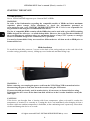
Novus NVR-6364-H8/R Instrukcja obsługi
- Kategoria
- Cyfrowe rejestratory wideo (DVR)
- Typ
- Instrukcja obsługi

User’ s ma n ual
(shor t )
NVR-6364-H8/R

NVR-6364-H8/R User’s manual (Short) version 1.3
All rights reserved © AAT SYSTEMY BEZPIECZEŃSTWA sp. z o.o.
2
IMPORTANT SAFEGUARDS AND WARNINGS
THE PRODUCT MEETS THE REQUIREMENTS CONTAINED IN THE FOLLOWING DIRECTIVES:
Information
The device, as a part of professional CCTV system used for surveillance and control, is not designed for
self installation in households by individuals without technical knowledge. The manufacturer is not
responsible for defects and damages resulted from improper or inconsistent with user’s manual
installation of the device in the system.
ATTENTION!
PRIOR TO UNDERTAKING ANY ACTION THAT IS NOT PROVISIONED FOR THE GIVEN
PRODUCT IN ITS USER’S MANUAL AND OTHER DOCUMENTS DELIVERED WITH THE
PRODUCT, OR THAT ARISES FROM THE NORMAL APPLICATION OF THE PRODUCT, ITS
MANUFACTURER MUST BE CONTACTED OR THE RESPONSIBILITY OF THE MANUFACTURER
FOR THE RESULTS OF SUCH AN ACTION SHELL BE EXCLUDED.
1. Prior to undertaking any action please consult the following manual and read all the safety and operating
instructions before starting the device.
2. Please keep this manual for the lifespan of the device in case referring to the contents of this manual is
necessary;
3. All the safety precautions referred to in this manual should be strictly followed, as they have a direct influence
on user’s safety and durability and reliability of the device;
4. All actions conducted by the servicemen and users must be accomplished in accordance with the user’s manual;
5. The device should be disconnected from power sources during maintenance procedures;
6. Usage of additional devices and components neither provided nor recommended by the producer is forbidden;
7. You are not allowed to use the device in high humidity environment (i.e. close to swimming pools, bath tubs,
damp basements);
8. Mounting the device in places where proper ventilation cannot be provided (e. g. closed lockers etc.) is not
recommended since it may lead to heat build-up and damaging the device itself as a consequence;
9. Mounting the device on unstable surface or using not recommended mounts is forbidden. Improperly mounted
device may cause a fatal accident or may be seriously damaged itself. The device must be mounted by qualified
personnel with proper authorization, in accordance with this user’s manual.
10. Device should be supplied only from a power sources whose parameters are in accordance with those specified
by the producer in the devices technical datasheet. Therefore, it is forbidden to supply the devices from a power
sources with unknown parameters, unstable or not meeting producer’s requirements;
11. You cannot allow any metal objects get inside the recorder. It might cause serious damage. If a metal object
gets inside the device contact the authorised Novus service immediately.
12. The manufacturer does not bear responsibility for damage or loss of data stored on HDDs or other media
occurred during the usage of the product.
Due to the product being constantly enhanced and optimized, certain parameters and functions described in the
manual in question may change without further notice.
We strongly suggest visiting the www.novuscctv.com website in order to access the newest manual.
Technical changes reserved without prior notice and printing errors possible.
The manual was created on the basis of software 1.4.1.26377B190419
DIRECTIVE 2014/30/EU OF THE EUROPEAN PARLIMENT AND OF THE
COUNCIL of 26 February 2014 on the harmonisation of the laws of the Member States
relating to electromagnetic compatibility (OJ L 96, 29.3.2014, p. 79–106, with changes)
DIRECTIVE 2014/35/EU OF THE EUROPEAN PARLIAMENT AND OF THE
COUNCIL of 26 February 2014 on the harmonization of the laws of the Member States
relating to the making available on the market of electrical equipment designed for use
within certain voltage limits.
DIRECTIVE 2012/19/EU OF THE EUROPEAN PARLIAMENT AND OF THE
COUNCIL of 4 July 2012 on waste electrical and electronic equipment (WEEE) (OJ L
197, 24.7.2012, p. 38–71,with changes)
DIRECTIVE 2011/65/EU OF THE EUROPEAN PARLIAMENT AND OF THE
COUNCIL of 8 June 2011 on the restriction of the use of certain hazardous substances in
electrical and electronic equipment (OJ L 174, 1.7.2011, p. 88–110, with changes)

NVR-6364-H8/R User’s manual (Short) version 1.3
All rights reserved © AAT SYSTEMY BEZPIECZEŃSTWA sp. z o.o.
3
FOREWORD INFORMATION
1. FOREWORD INFORMATION
1.1. Network recorder’s technical data
NVR-6364-H8/R
VIDEO
IP Cameras up to 64 channels at 3840 x 2160 resolution (video + audio)
Maximum Supported Camera Reso-
lution
3840 x 2160
Compression H.264, H.264+, H.265, H.265+, H.265 Smart
Monitor Output main (split screen, full screen, sequence): 1 x VGA, 1 x HDMI (4K UltraHD)
spot: 1 x HDMI (FullHD)
Dualstreaming Support yes
Fisheye Support yes, 3000/6000 IP series cameras
AUDIO
Audio Output 1 x line-out (RCA) 1 x HDMI
RECORDING
Recording Speed 1920 fps (64 x 30 fps for 3840 x 2160 and lower)
Stream Size 320 Mb/s in total from all cameras
Recording Mode time-lapse, triggered by: manual, alarm input, motion detection, intelligent image analysis func-
tions
Prealarm/Postalarm up to 5 s/up to 600 s
DISPLAY
Display Speed 1920 fps (64 x 30 fps)
PLAYBACK
Playback Speed 480 fps (16 x 30 fps)
Recorded Data Search by date/time, events, motion in a defined area, related to face recognition
BACKUP
Backup Methods USB port (HDD or Flash memory), network
Backup File Format AVI, RPAS (player included)
STORAGE
Internal Storage available mount: 8 x HDD 3.5” 14 TB SATA
Total Internal Capacity 112 TB
RAID Mode RAID0, RAID1, RAID5, RAID6, RAID10
ALARM
Internal Alarm Input/Output 8/4 relay type
Camera Alarm Input/Output supports camera’s alarm input/output
Motion Detection supports camera’s motion detection
System Reaction to Alarm Events buzzer, e-mail, alarm output activation, recording activation, PTZ
INTELLIGENT IMAGE ANALYSIS
Supported Functions Exception, Scene Change, Video Blurred, Video Color Cast, Tripwire, Zone entrance, Abandoned
Object, Object Disappearance, Face Detection, Perimeter Intrusion Detection by pedestrian or
vehicle, Line Cross Detection by pedestrian or vehicle
NETWORK
Network Interface 2 x Ethernet - RJ-45 interface, 10/100/1000 Mbit/s
Network Protocols Support HTTP, TCP/IP, IPv4, HTTPS, FTP, DHCP, DNS, DDNS, NTP, RTSP, UPnP, SNMP, SMTP
ONVIF Protocol Support Profile S (ONVIF 2.2 or higher)
PC/MAC Software NMS, Internet Explorer, NVR-6000 Viewer, N Control 6000/N Control 6000
Mobile applications SuperLive Plus (iPhone, Android)
Number of Simultaneous Connec-
tions
up to 20 clients, up to 68 main streams or 256 substreams or 32 playback streams in total
Bandwidth 320 Mb/s in total to all client workstations
PTZ
PTZ Functions pan/tilt/zoom, preset commands
AUXILIARY INTERFACES
USB Ports 2 x USB 2.0, 1 x USB 3.0
OPERATING SYSTEM
Operating System Linux
OSD languages: Polish, English, others
Control PC mouse and IR remote controller (in-set included), network
System Diagnostic automatic control of: HDDs, network, camera connection loss
Security password protection, IP filtering, MAC filtering
INSTALLATION PARAMETERS
Dimensions (mm) 430 (W) x 90 (H) x 453 (D)
Weight 6 kg (without HDD)
Power Supply 100 ~ 240 VAC
Power Consumption 175 W (with 8 HDDs)
Operating Temperature -10°C ~ 50°C
RACK Mount 19" 2U

NVR-6364-H8/R User’s manual (Short) version 1.3
All rights reserved © AAT SYSTEMY BEZPIECZEŃSTWA sp. z o.o.
4
FOREWORD INFORMATION
1.2. Main characteristics
• Supports resolution up to 3840 x 2160
• Supported protocols: ONVIF
• Recording up to 3840 x 2160
• Recorded stream size up to 256 Mb/s in total from all cameras
• Internal HDDs mount up to 8
• 2 x Ethernet - RJ-45, 10/100/1000 Mbit/s
WARNING!
ONVIF protocol support was verified with IP cameras based on ONVIF ver. 2.2 and compatible
with the "PROFILE S".
Implementation of the ONVIF protocol by different manufacturers may vary by some functions,
which can make them work improperly or not in accordance with expectation. AAT SYSTEMY
BEZPIECZEŃSTWA SP. Z O.O. is not responsible for incompatibility problems resulting from
cameras of other brands than NOVUS, which are using ONVIF protocol. If you are using
ONVIF protocol cameras other than NOVUS brand it is recommended to test each time whether
required functions work correctly.
1.3. Package contents
Unpack the device carefully. After unpacking, please ensure that package contains the following items:
• Network Video Recorder
• USB Mouse
• Remote control
• User’s manual (short)
If any of the elements has been damaged during transport, pack all the elements back into the original
packaging and contact your supplier.

NVR-6364-H8/R User’s manual (Short) version 1.3
All rights reserved © AAT SYSTEMY BEZPIECZEŃSTWA sp. z o.o.
5
STARTING THE DEVICE
2. STARTING THE DEVICE
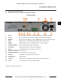
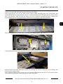
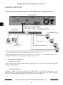
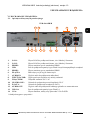
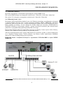
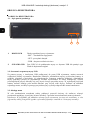
2.1 Electrical connection and other back panel elements.
NVR-6364-H8/R
1. LAN1: RJ-45 connector port to connect to the local network and internet.
2. LAN2: RJ-45 connector port to connect to the local network and internet.
3. HDMI2: SPOT monitor connector, use the HDMI cable to connect SPOT monitor
4. USB: USB port for external Flash memory and other USB devices.
5. HDMI: HDMI connector, use the HDMI cable to connect monitor
6. CONNECTORS : Block of alarm input/output connectors
7. AUDIO IN: Audio mono inputs to connect microphones*.
8. FAN : Air outlet of the power supply, do not cover
9. POWER SWITCH: Power switch
10. POWER SOCKET: To plug in the 230 V power cord.
11. E-SATA: Sockets for connecting E-SATA devices
12. AUDIO OUT : Audio output
13. USB 3.0 : USB port for external Flash memory and other USB devices.
14. VGA: VGA connector, to connect VGA monitor
* Will be available in the future.
5
4
1
14
8
9
11
10
2
3
13
6
7
12

NVR-6364-H8/R User’s manual (Short) version 1.3
All rights reserved © AAT SYSTEMY BEZPIECZEŃSTWA sp. z o.o.
6
STARTING THE DEVICE
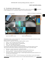
2.2 HDD mounting
Novus NVR-6364-H8/R supports up to 8 internal SATA HDDs.
WARNING!
In order to find information regarding the compatible models of HDDs and their maximum
capacities, please contact Novus distributor or check the information presented at
www.novuscctv.com. AAT SYSTEMY BEZPIECZEŃSTWA SP. Z O.O. is not responsible for
any problems from using not recommended hard drives.
The list of compatible HDDs contains all the HDDs that can be used with a given DVR including
HDDs designed for office use - so called desktop disks. However, due to the fact that reliability of
the recording process and data safety are paramount factors of any CCTV system, we strongly
advise to use HDDs designed for continuous (24/7) operation.
You need to format disks if they were used in a different device. All data saved on HDD prior to
format will be lost.
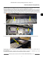
HDDs Installation
To install the hard disks, unscrew 3 screws on the back of the casing and two on the each side of the
recorder casing (pointed by arrows), sliding top cover backwards and then lifting it up.
WARNING: !
Before removing cover unplug the power cord from the NVR. When NVR is turned on before
disconnecting the power cord, shut down the recorder using the NVR menu.
If you use the disk previously used in another device, it is necessary to format it before using.
Formatting the drive erase all the data from disk. All drives in the recorder should be exactly the
same type.
CAUTION!
If the device was brought from a location with lower temperature, please wait until it reaches the
temperature of location it is currently in. Turning the device on immediately after bringing it from a
location with lower ambient temperature is forbidden, as the condensing water vapour may cause short-
circuits and damage the device as a result.

NVR-6364-H8/R User’s manual (Short) version 1.3
All rights reserved © AAT SYSTEMY BEZPIECZEŃSTWA sp. z o.o.
7
STARTING THE DEVICE
By default, SATA cables are packed together with DVR accessories, while HDD power cable is
connected to the DVR PSU and ready for connecting the HDD.
After removing top cover of the NVR, please remove HDD mounting racks (top and bottom) and
mount HDDs to them using included screws. To dismount them from NVR take out two screws on the
side of the housing. After screwing the disks to the rail it should be remembered that to install posts
supporting the top rail. The bottom rail is supported on two supports with a threaded hole.
When reinstalling the rails with disks, screw the posts supporting the upper rail.
After installing the upper rail, screw the rail to the posts using the screws provided.
Mounted rails with disks should be secured by screwing out screws to the side of the housing and
connect power/signal cables.
After connecting disks, please put the top cover onto the NVR and turn the device on in order to check
the operation of particular components and to format the HDDs.

NVR-6364-H8/R User’s manual (Short) version 1.3
All rights reserved © AAT SYSTEMY BEZPIECZEŃSTWA sp. z o.o.
8
STARTING THE DEVICE
2.3 Connecting the HDD to the NVR via the eSATA port
The recorders allow you to connect one external drive via the eSATA port. An external hard drive
connected via the eSATA port, like the internal HDD of the recorder, is used to record recordings.
NOTE: Before connecting or disconnecting the drive to the eSATA port, first turn off the DVR.
2.4. Connecting the power supply.
Please connect provided power cord in the rear power port of the NVR like described below.
To start the unit turn on the power switch on back panel. Initialization lasts approximately 60 seconds.
During this time executing any device functions and pressing any buttons is prohibited. To shut down
the device please use the menu.
CAUTION:
Make connection when the power is not applied and the power switch is turned off.
Do not place the power cord under the carpet or rug. The power cord is usually earth-grounded.
However, even if it's not earth-grounded, never modify it on your own for earth-grounding.
Make sure that power adapter is placed near of NVR and secured from accidental disconnection.
If the device was brought from a location with lower temperature, please wait until it reaches the
temperature of location it is currently in. Turning the device on immediately after bringing it
from a location with lower ambient temperature is forbidden, as the condensing water vapour
may cause short-circuits and damage the device as a result.
Before starting the device familiarize yourself with the description and the role of particular
inputs, outputs and adjusting elements that the device is equipped with.

NVR-6364-H8/R User’s manual (Short) version 1.3
All rights reserved © AAT SYSTEMY BEZPIECZEŃSTWA sp. z o.o.
9
2.5. Connecting monitor
This product supports following interfaces for main monitor: HDMI, VGA.
For HDMI following resolutions are supported: 1280x1024, 1920x1080 i 3840x2160.
The following resolutions are available for the VGA output: 1280x1024, 1920x1080.
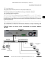
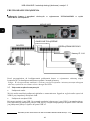
2.6. Connecting camera and Network
The NVR-6364-H8/R has two Ethernet ports for connecting the DVR in two modes. The first mode in
the recorder menu called MULTIPLE ADDRESS SETTINGS allows you to connect NVRs to
networks with different IP addresses. This mode allow to separate network with network cameras
from NVR access network. The second mode, called NETORK FAULT TOLERNANCE allows one
of network sockets of the recorder to be used as an active fault tolerant connection in case if the main
of main connections fails.
The permissible cable distance from the switch to each camera is 100m. Cameras, Internet and other
devices should be connected as shown below.
We recommend that you configure the camera before connecting to a recorder, as described in the
user manual of the camera. Please note that cameras have addressed the unique IP address supported
by the recorder. .
Connecting cameras and network recorder NVR-6364-H8/R in MULTIPLE ADDRESS
SETTING
STARTING THE DEVICE
NOVUS NVR
INTERNET
PC
COMPUTER
IP CAMERAS
1-64
NETWORK SWITCH ROUTER

NVR-6364-H8/R User’s manual (Short) version 1.3
All rights reserved © AAT SYSTEMY BEZPIECZEŃSTWA sp. z o.o.
10
Connecting NVR-6364-H8/R and cameras in NETWORK FAULT TOLERNACE mode.
Note: In order to ensure stability and protection against overload and unauthorized access, we
recommend separating the network monitoring of LANs used by users.
Before configuring the connection of the cameras in the recorder, we recommend using a PC to
configure the cameras according to the instructions of the camera.
2.7. Connecting external devices
• Connecting audio ports
Audio output signal normally are above 200mV @1kΩ load. You can connect to it the audio amplifier
with the external speakers.
• Connecting USB devices
NVR has 1 x USB 2.0 port on front and one 1 x USB 2.0 and 1 x 3.0 USB port on back panel . They
could be used for connecting external Flash memory, mouse connection and other USB compatible
devices. To connect storage memory it is recommended to use port USB 3.0
STARTING THE DEVICE
NOVUS NVR
INTERNET
PC
COMPUTER
IP CAMERAS 1-64
NETWORK SWITCH
ROUTER
BACKUP CONNECTIONS

NVR-6364-H8/R User’s manual (Short) version 1.3
All rights reserved © AAT SYSTEMY BEZPIECZEŃSTWA sp. z o.o.
11
• Connecting alarms ports
Example of connecting alarm output no. 1, follow the drawing below:
NOTE: The current parameters from the power supply should not exceed 3A 250 V for alternating
current and 3 A 30 V for direct current.
Example of sensor connection to alarm input 1.
STARTING THE DEVICE
NO1 COM1
ALARM
Power
source
GND
Alarm in
Alarm out
RS485
ALARM IN 1
SENSOR
GND

NVR-6364-H8/R User’s manual (Short) version 1.3
All rights reserved © AAT SYSTEMY BEZPIECZEŃSTWA sp. z o.o.
12
NVR OPERATING
3. NVR OPERATING
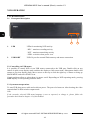
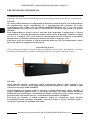
3.1. Front panel description
1. LED LEDs for monitoring NVR activity.
- REC - monitors recording activity
- NET - monitors networking activity
- PWR - activities when power is on
2. USB PORT USB 2.0 port for external Flash memory and mouse connection.
.
3.2. Controlling via USB mouse
It is possible to control NVR via an USB mouse connected to the USB port. Double-click on any
camera in split screen display mode switches the display to full-screen mode. Subsequent double-click
returns to previous display mode. Move cursor to the top or click the right key of mouse to bring up
MAIN MENU and select START icon.
Certain positions allow to select them via mouse scroll. Depending on NVR operating mode, pressing
RMB displays a corresponding function menu.
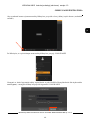
3.3. System menu operations
To start NVR plug power cable and switch on power. The power led turns on. After booting, the video
output default is multi-window output mode.
Note:
If the currently selected NVR menu language is not as expected, to change it, please follow the
procedure described in chapter 4.3 of this manual.
1
2

NVR-6364-H8/R User’s manual (Short) version 1.3
All rights reserved © AAT SYSTEMY BEZPIECZEŃSTWA sp. z o.o.
13
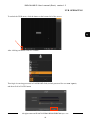
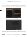
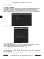
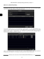
To unlock the DVR menu, click the button at the bottom left of the screen.
After clicking on button click-on “LOGIN”
Then login in entering password in PASSWORD field (default password for user root is pass)
and then click-in LOGIN button
NVR OPERATING

NVR-6364-H8/R User’s manual (Short) version 1.3
All rights reserved © AAT SYSTEMY BEZPIECZEŃSTWA sp. z o.o.
14
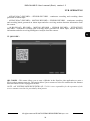
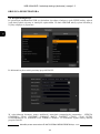
3.4. Startup configuration
After the first start-up of the NVR, a window is displayed enabling you to select the language used in
the menu (window on the left) and the device location in (window on the right). Clicking the left mouse
button in the window changes the setting. Select language in the window on the left.
After choosing the language go to the next menu, click on the NEXT button.
The next wizard window allows you to set time parameters such as TIME ZONE, SYSTEM TIME,
DATE FORMAT, TIME FORMAT, DST, SYNCHRONUS, NTP SERVER, and VIDEO FORMAT.
After completing parameter configuration, right-click on the NEXT button.
NVR OPERATING

NVR-6364-H8/R User’s manual (Short) version 1.3
All rights reserved © AAT SYSTEMY BEZPIECZEŃSTWA sp. z o.o.
15
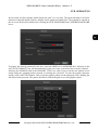
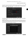
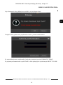
In next menu you must change default password “pass” for root user. The password must be at least 8
characters long and should contain a number and a capital and small letter. They should be entered in
the on-screen keyboard available after clicking the NEW PASSWORD and CONFIRM PASSWORD
boxes
To display the entered password in the box, select the DISPLAY PASSWORD box. Selecting in the
LOG IN AUTOMATIC box will automatically log the user to the system after the recorder is started.
Selecting the ENABLE field in the GRAPHIC LOCK row allows you to run the user unlock access
setting using the graphical pattern instead of entering the password. To start the graphic character
setting, click on the EDIT button. Then select the graphic pattern on the displayed circles holding the
left mouse button pressed. The pattern should be confirmed again to save the graphic pattern.
NVR OPERATING

NVR-6364-H8/R User’s manual (Short) version 1.3
All rights reserved © AAT SYSTEMY BEZPIECZEŃSTWA sp. z o.o.
16
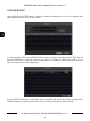
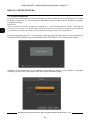
After clicking on the NEXT button, a window is displayed enabling you to set a set of questions and
answers that can unlock access to the recorder.
To add a question, click on the QUESTION box to enter a question using the keyboard. Then click on
the field ANSWER to enter the answer to the question. Clicking the ADD button adds a set of
questions and answers. Clicking the NEXT button goes to the window in which information about the
disk connected to the recorder is displayed.
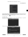
If in the STATUS field there is information about unavailable disk, format the disk by clicking on the
FORMAT button. A window appears asking you to confirm the intention to format the disk.
NVR OPERATING

NVR-6364-H8/R User’s manual (Short) version 1.3
All rights reserved © AAT SYSTEMY BEZPIECZEŃSTWA sp. z o.o.
17
Press the OK button to confirm the intention to format the disk.
To run the format, enter the username and password for the user with administrator rights.
After entering the username and password, press the FORMAT NOW button.
After successful formatting, the disk should have the status "READ AND WRITE".
NVR OPERATING

NVR-6364-H8/R User’s manual (Short) version 1.3
All rights reserved © AAT SYSTEMY BEZPIECZEŃSTWA sp. z o.o.
18
3.5 Startup Wizard configuration
Prior to using NVR for the first time, initial setup is strongly advised. Before you connect the IP
cameras to the NVR, please set up network and stream parameters of IP cameras in the right way.
Note:
For suggested values for IP camera setting please refer to the “Cameras Capability Table” available
on the www.novuscctv.com website. If you set wrong values some problems may appear: the NVR
cannot search the IP camera, the stream cannot be connected, the image is not fluent, the image quality
is bad and so on.
In case of first NVR start WIZARD SETUP menu window will occur (if function wasn’t disabled
earlier). To configure NVR please follow procedure like below, after finishing all the steps you’ll be
ready to work:
Provide username and password and click on NEXT button so start wizard.
NVR OPERATING

NVR-6364-H8/R User’s manual (Short) version 1.3
All rights reserved © AAT SYSTEMY BEZPIECZEŃSTWA sp. z o.o.
19
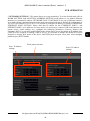
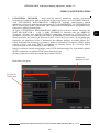
I. NETWORK SETTINGS : This menu allows to set up networking. To select desired mode clik-on
WORK PATTERN field. MULTIPLE ADDRESS SETTING mode allows to use address Ethernet
Interfaces in separated IP subnets. NETWORK FAULT TOLERANCE uses one of Ethernet interface
as an fault tolerant connection activated after main connection break down. Default IP configuration is
192.168.1.100 netmask 255.255.255.0. It is possible to configure IP address for switch in INTERNAL
ETHERNET PORT SECTION. Please note that IP subnet for the ETHERNET PORT 1 and
ETHERNT PORT 2 were different. In cases where it is necessary to connect NVR to the Internet (for
remote access, email sending, etc.), configure the following parameters: Gateway, Primary and
Secondary DNS. You can also enable DHCP mode which allows you to download an IP address from
a DHCP server (required if running a DHCP server). It is possible to change the default HTTP port
designed to display Web panel of the device and RTSP ports and port server data. After changing
parameter pres NEXT button.
NVR OPERATING
Ports 2 IP address
settings
Port 1 IP address
settings
Work pattern selction

NVR-6364-H8/R User’s manual (Short) version 1.3
All rights reserved © AAT SYSTEMY BEZPIECZEŃSTWA sp. z o.o.
20
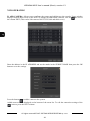
II. ADD CAMERA: Allows you to configure the camera and add them to the recorder. Upper window
displays cameras discovered by the NVR. To change the addressable cameras, click on the icon in
the column EDIT (This works with cameras NOVUS IP 3000 and 6000 series).
Enter the address in the IP ADDRESS and set the masks in the SUBNET MASK then press the OK
button to save the settings.
Press the button to add a camera to the system.
Added camera will be displayed on the bottom of the menu list. To edit the connection settings of the
camera, press the EDIT column
NVR OPERATING
Strona się ładuje...
Strona się ładuje...
Strona się ładuje...
Strona się ładuje...
Strona się ładuje...
Strona się ładuje...
Strona się ładuje...
Strona się ładuje...
Strona się ładuje...
Strona się ładuje...
Strona się ładuje...
Strona się ładuje...
Strona się ładuje...
Strona się ładuje...
Strona się ładuje...
Strona się ładuje...
Strona się ładuje...
Strona się ładuje...
Strona się ładuje...
Strona się ładuje...
Strona się ładuje...
Strona się ładuje...
Strona się ładuje...
Strona się ładuje...
Strona się ładuje...
Strona się ładuje...
Strona się ładuje...
Strona się ładuje...
Strona się ładuje...
Strona się ładuje...
Strona się ładuje...
Strona się ładuje...
Strona się ładuje...
Strona się ładuje...
Strona się ładuje...
Strona się ładuje...
Strona się ładuje...
Strona się ładuje...
Strona się ładuje...
Strona się ładuje...
-
 1
1
-
 2
2
-
 3
3
-
 4
4
-
 5
5
-
 6
6
-
 7
7
-
 8
8
-
 9
9
-
 10
10
-
 11
11
-
 12
12
-
 13
13
-
 14
14
-
 15
15
-
 16
16
-
 17
17
-
 18
18
-
 19
19
-
 20
20
-
 21
21
-
 22
22
-
 23
23
-
 24
24
-
 25
25
-
 26
26
-
 27
27
-
 28
28
-
 29
29
-
 30
30
-
 31
31
-
 32
32
-
 33
33
-
 34
34
-
 35
35
-
 36
36
-
 37
37
-
 38
38
-
 39
39
-
 40
40
-
 41
41
-
 42
42
-
 43
43
-
 44
44
-
 45
45
-
 46
46
-
 47
47
-
 48
48
-
 49
49
-
 50
50
-
 51
51
-
 52
52
-
 53
53
-
 54
54
-
 55
55
-
 56
56
-
 57
57
-
 58
58
-
 59
59
-
 60
60


Novus NVR-6364-H8/R Instrukcja obsługi
- Kategoria
- Cyfrowe rejestratory wideo (DVR)
- Typ
- Instrukcja obsługi
w innych językach
- English: Novus NVR-6364-H8/R User manual
Powiązane artykuły
-
Novus NVR-6364-H8/R Instrukcja obsługi
-
Novus NVR-6332-H2/F Instrukcja obsługi
-
-
-
-
-
-
-
-
Inne dokumenty
-
DeLOCK 42481 Karta katalogowa
-
Sharkoon 4044951010073 Karta katalogowa
-
 MGDVRs LIVCAP series Installation and User Manual
-
CAME XDTVI23 Instrukcja instalacji
-
Velleman CCTVPROM14 Instrukcja instalacji
-
AVTech - Velleman CCTVPROM17 Instrukcja obsługi
-
PNI House WiFi550 Instrukcja obsługi
-
 Nanopoint ICY DOCK MB-559UEB-1S Karta katalogowa
-
Tracer TRAKAM43592 Instrukcja obsługi

