Munters 14-24 AT Classic Instrukcja obsługi
- Typ
- Instrukcja obsługi

1© Munters Corporation, July 2020
QM1050r9
Instruction Manual
Classic ‘AT’ Fans Direct Drive
Models: AT14F • AT16F • AT16G • AT18F • AT18G • AT24F •
AT24G • AT24F3 • AT24G3
14” - 24”
CLASSIC ‘AT’
Direct Drive
14” - 24” Fans
AT24F
AT24G

© Munters Corporation, July 2020
2
QM1050r9
Classic ‘AT’ Fan Direct Drive 14”, 16”, 18”, 24” Fans
Instructions for Use and Maintenance
Thank You:
Thank you for purchasing a Munters Classic Fan Direct Drive. Munters equipment is designed to be the highest
performing, highest quality equipment you can buy. With the proper installation and maintenance it will provide
many years of service.
Please Note:
To achieve maximum performance and insure long life from your Munters product it is essential that it be installed
and maintained properly. Please read all instructions carefully before beginning installation.
Warranty:
For Warranty claims information see the “Warranty Claims and Return Policy” form QM1021 available from the
Munters Corporation office at 1-800-227-2376 or by e-mail at [email protected].
Conditions and Limitations:
• Products and Systems involved in a warranty claim under the “Warranty Claims and Return Policy” shall have
been properly installed, maintained and operated under competent supervision, according to the instructions
provided by Munters Corporation.
• Malfunction or failure resulting from misuse, abuse, negligence, alteration, accident or lack of proper installation
or maintenance shall not be considered a defect under the Warranty.

3© Munters Corporation, July 2020
QM1050r9
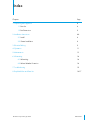
Index
Chapters Page
1. Unpacking the Equipment 4
1.1 Parts List 4
1.2 Fan Dimensions 5
2. Installation Instructions 6-8
2.1 Install 6
2.2 Shutter Installation 8
3. Electrical Wiring 9
4. Operation 11
5. Maintenance 13
6. Winterizing 14
6.1 Winterizing 14
6.2 Winter Weather Protection 14
7. Troubleshooting 15
8. Exploded View and Parts List 16-17

© Munters Corporation, July 2020
4
QM1050r9
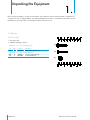
1.1 Parts List
Unpacking the Equipment
1.
[A]
[B]
[C]
Each Fan includes:
1 – Direct Drive Fan
1 – Hardware Package as follows:
HP1076 – 14” - 24” Fiberglass Fans
ID Qty. Cat. No. Description
[A] 8 KS2105 #14 x 1.5” Lag Screw, SS
HP1008 – 16” - 24” Galvanized Fans
[B] 8 KS2463 ¹⁄₄” x 1.5” Lag Screw, ZP
[C] 8 KW3001 ¹⁄₄” Flat Washer, ZP
Before beginning installation, check the overall condition of the equipment. Remove packing materials, and examine all
components for signs of shipping damage. Any shipping damage is the customer’s responsibility and should be reported
immediately to your freight carrier. Fan is shipped complete with all accessories.

5© Munters Corporation, July 2020
QM1050r9
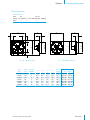
1.2 Fan Dimensions
Unpacking the EquipmentChapter 1
16” - 24” Galvanized Fans14” - 24” Fiberglass Fans
DD
E - Dia.
A
A
D
B
C
Fan Specifi cations:
Hertz: 60 50 - 60
Voltage: 115/230VAC or 190 - 208-230/380 - 460VAC
Phase: 1 or 3
3 Phase fans only available for AT24
CAT.
NO.
FAN
DIA.
NO. OF
BLADES
A B C D
E - Dia.
(O.D.)
WALL OPENING
(I.D., framed)
AT14F 14” 7 19
5
⁄8” 3
1
⁄2” 10
3
⁄4” 3
1
⁄2” 14
1
⁄2” 17
1
⁄4”W 17
1
⁄4”H
AT16F 16” 4 22
5
⁄8” 4
1
⁄4” 11
1
⁄8” 4
1
⁄4” 16
1
⁄2” 20
1
⁄$”W 20
1
⁄4”H
AT16G 16” 4 20” 4
3
⁄4” 10
1
⁄4” 4
3
⁄4” 16
1
⁄2” 20
1
⁄$”W 20
1
⁄4”H
AT18F 18” 5 24
5
⁄8” 4
1
⁄4” 12” 4
1
⁄4” 18
1
⁄2” 22
1
⁄4”W 22
1
⁄4”W
AT18G 18” 5 22” 4
5
⁄8” 11" 4
5
⁄8” 18
1
⁄2” 22
1
⁄4”W 22
1
⁄4”W
AT24F 24” 4 30
3
⁄4” 5
1
⁄4” 12
1
⁄8” 5
1
⁄4” 24
1
⁄2” 28
1
⁄4”W 28
1
⁄4”H
AT24G 24” 4 28” 5
7
⁄8” 11
3
⁄8” 5
7
⁄8” 24
1
⁄2” 28
1
⁄4”W 28
1
⁄4”H
A
A
B
C
D
E - Dia.

© Munters Corporation, July 2020
6
QM1050r9
Installation Instructions
2.
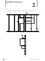
2.1 Install
Figure 1
Ceiling
Framing
12"
Wall
Opening
(See Chart on
previous page)
8”
Min.
Step 1
Construct the framed opening to correct size according to the Chart on the previous page.
See Figure 1 and 2.
Wall
Opening
(See Chart on
previous page)
2x Framing
Wall Opening
15"
MIN.
Figure 2

7© Munters Corporation, July 2020
QM1050r9
Installation InstructionsChapter 2
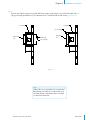
Step 2
Insert fan into framed opening from outside and fasten in place using (8) Lag Screws [A] for Fiberglass Fans or
(8) Lag Screws [B] and Washers [C] for Galvanized Fans. Flash and caulk around opening.
See Figure 3.
Note:
Outlet of fan comes unguarded, it is recommended
that a Munters Discharge Cone with Guard, a Fan
Hood with Guard or a guard by others is installed
on outlet of fan at this time.
Fiberglass
Fan
Figure 3
2x Framing
2x Framing
Washer [C]
15"
MIN.
15"
MIN.
Galvanized
Fan
Lag Screw [B]
Lag Screw [A]

© Munters Corporation, July 2020
8
QM1050r9
Installation InstructionsChapter 2
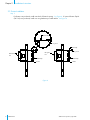
2.2 Shutter Installation
Step 3
If a Shutter was purchased, install it into back of framed opening. See Figure 4. If optional Shutter Clip Kit
(FH1192) was purchased, install now using hardware provided with kit. See Figure 4.
Shutter Clip
Shutter
Figure 4
Shutter Clip
Lag Screw
Galvanized
Fan
Fiberglass
Fan
Shutter Clip
Shutter
Shutter Clip
Lag Screw

9© Munters Corporation, July 2020
QM1050r9
Electrical Wiring
3.
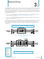
All wiring should be installed in accordance with National, State, and Local electrical codes. Fans used to ventilate
livestock buildings or other rooms where continuous air movement is essential should be connected to individual
electrical circuits, with a minimum of two circuits per room. For electrical connection requirements, refer to diagram
on motor nameplate and to information enclosed with the Munters environmental control to be used. After wiring
check for proper motor rotation.
Single Phase Fans: motor overload protection should be provided for each fan. A Circuit Breaker Switch or slow
blow motor type fuses must be used, See Figure 6A. See form QM1400 for proper size.
Three Phase Fans: motor overload protection should be provided for each fan. A three-pole motor starter or slow
blow motor fuses must be used. See Figure 6B.
If a frequency drive (inverter) is used, confirm that motors are rated for inverter duty at the voltage used. Shielded
power cable between frequency drive and each motor is highly recommended. Installation of line reactors is
recommended to reduce voltage spikes and harmonic distortion. Supplemental motor overload protection is also
recommended.
NOTE: A safety cut-off switch should be located adjacent to each fan.
Figure 6A
Single Phase - Motor Overload Protection with Disconnect
(SY2000 or Equivalent)
KEY:
L1=Line 1
L2=Line 2
L3=Line 3
H=Hot
N=Neutral
G=Ground
NOTE: Information in parenthesis refers to 120 VAC control.
Figure 6B
Three Phase - Motor Overload Protection with Disconnect

© Munters Corporation, July 2020
10
QM1050r9
Electrical WiringChapter 3
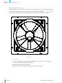
Three Phase Fans:
1)
The use of a quality frequency drive and the installation of line reactors is recommended to
reduce voltage spikes and harmonic distortion.
2) Minimum operating frequency of 30 Hz.
3) Will require three pole contractors with overload protection (by others).
As the power cable exits the back of motor form a drip loop and then run power cable down along leg
of motor mount and "Zip" tie the cable to leg to prevent cable from getting tangled.
See Figure 7.
Then
run the cable out the drain hole to the circuit breaker or control panel. (Continued on next page).
Figure 7
3.1 Recommended Wire Routing:

11© Munters Corporation, July 2020
QM1050r9
Operation
4.
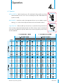
INITIAL START-UP: With electrical power off, verify that the fan propeller turns freely
and that all fasteners are secure. Turn on electrical power and confirm that the fan
operates smoothly.
ADJUSTMENTS: Set the fan control to the temperature shown on your ventilations system
drawing, or to a value which will provide the desired environmental conditions.
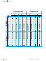
Single Phase Fans: When variable speed controls are used, the fan's idle speed will need
to be set to the recommended minimum airflow rate. Refer to the procedures included with
each control. The table below provides airflow rates at various propeller speeds for fans
wired for 240 VAC.
WARNING
!
Disconnect Power
before servicing
WARNING
!
Moving parts, disconnect
power before servicing.
4.1 Operation

© Munters Corporation, July 2020
12
QM1050r9
OperationChapter 4

13© Munters Corporation, July 2020
QM1050r9
Maintenance
5.
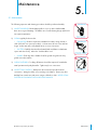
5.1 Maintenance
The following inspection and cleaning procedures should be performed monthly:
1) INSPECT PROPELLER: Check that propeller is secure on motor shaft and that
there are no signs of damage. The blades are of a self-cleaning design and should
not require maintenance.
2) CLEAN regularly for best results:
• FAN MOTOR: Remove any dust accumulation from motor using a brush or
cloth. (DO NOT use a pressure washer). A clean motor will run cooler and last
longer. At the same time, verify that the motor is secure in its mount.
• SHUTTER: Carefully clean dust from shutter blades and frame so that shutter
opens and closes freely. A brush or cloth should be used.
• GUARD: Clean any dust or feathers from fan guards using a brush. Dirty
guards can reduce airflow.
3) CHECK FASTENERS: For safety, all fasteners should be inspected 1 month after
initial operation and yearly thereafter. Tighten any loose connections.
4) INSPECT FAN CONTROL: With power disconnected, inspect all electrical
connections. Wiring should be secure and in good condition. Remove any dust
build-up from control case and sensor using a soft brush or cloth. NEVER CLEAN
ELECTRICAL EQUIPMENT WITH A PRESSURE WASHER!
WARNING
!
Disconnect Power
Before Servicing
WARNING
!
Moving Parts, Disconnect
Power Before Servicing.
WARNING
!
Do Not Power Wash
Electrical Devices.

© Munters Corporation, July 2020
14
QM1050r9
Winterizing
6.
In most climates, it is probable that the ventilation system will never need to operate at a total capacity during
the colder winter months. Consequently, it is advisable to “winterize” those fans which will not be used in cold
weather to avoid unnecessary heat loss and condensation.
To winterize, turn fan control “off”. Install the insulated closure panel over the fan intake. If you don’t have an
insulated closure panel, a piece of rigid insulation material can be used. Remember the insulation panel must
be removed before warmer weather returns.
NOTE: At least one single speed fan should be left uncovered and with power available to provide air
movement in the event of variable speed control difficulties.
6.1 Winterizing
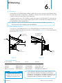
6.2 Winter Weather Protection
To prevent cone or fan damage from snow or ice sliding off building roof, weather protection must be
provided. A weather shelter may be constructed to cover the entire fan, See Figure 8, or snow guards may be
placed on the roof, See Figure 9.
Building
Wall
Provide Weather
Shelter Over Fans
6" Min.
Fan with
Discharge Cone
Figure 8
Note: Snow guards are designed to prevent sudden, dangerous snow
and ice slides when attached to the building roof according to
manufacturers recommendations. The supplier listing above is given
as a reference only. Munters does not endorse any specific snow
guard product and no performance warranty is implied.
Munters Product and System
Warranties do not cover cone or fan
damage from external sources.
IMPORTANT
!
Snojax, Inc. 800-766-5291 717-697-2452 www.snojax.com
Polar Blox 800-298-4328 814 629-9090 www.polarblox.com
LM Curbs 800-284-1412 903 759-3598 www.lmcurbs.com
Alpine Snow Guards 888-766-4273 888-766-9994 www.alpinesnowguards.com
*Snow Guard Suppliers
Company Name Phone No. Fax No. Web Site
Snow Guards located
per manufacturers
recommendations*
Ceiling
Figure 9
Fan with
Discharge
Cone

15© Munters Corporation, July 2020
QM1050r9
Troubleshooting
7.
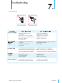
7.1 Troubleshooting
WARNING
!
High Voltage, disconnect
power before servicing.
WARNING
!
Moving parts, disconnect
power before servicing.
1. Fan control set above room
temperature
2. Blown fuse or open circuit breaker
3. Propeller blade contacting fan housing
4. Fan control defective
5. Motor defective
1. Variable speed control improperly
adjusted
2. Shutter jammed or dirty
3. Guard dirty
1. Propeller blade contacting fan housing
2. Motor bearing or shaft bearing defective
3. Frequency drive improperly adjusted
1. Motor loose on mount
2. Propeller damaged
3. Motor shaft bent
1. Set to a lower temperature
2. Replace fuse or reset breaker
3. Realign motor in fan housing
4. Repair or replace control
5. Repair or replace motor
1. See Operation, Step 2 for adjustment guidelines
2. Unjam and clean shutter
3. Clean guard
1. Sand fan housing to remove high spot
2. Repair or replace motor or shaft bearings
3. See operation, Step 2 for adjustments guidelines
1. Tighten fasteners
2. Replace propeller
3. Repair or replace motor
1. Override thermostat set incorrectly
2. Control set for continuous operation
1. Set to the correct temperature
2. Set speed control correctly

© Munters Corporation, July 2020
16
QM1050r9
Exploded View
8.

17© Munters Corporation, July 2020
QM1050r9
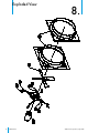
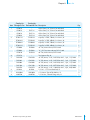
Parts ListChapter 8
Item
Catalog No
.
Fiberglass Fan
Catalog No
.
Galvanized Fan
Description
Qty.
1 FH3014 -- Orifi ce Panel, 14” Classic Fan with Labels 1
FH3016 FH3116 Orifi ce Panel, 16” Classic Fan with Labels 1
FH3018 FH3118 Orifi ce Panel, 18” Classic Fan with Labels 1
FH3024 FH3124 Orifi ce Panel, 24” Classic Fan with Labels 1
2 FP1031SS FP1031SS Propeller, 14”DD, 7-Blade, Set Screws, AL 1
FP1038SS FP1038SS Propeller, 16”DD, 4-Blade, Set Screws, AL 1
FP1008SS FP1008SS Propeller, 18”DD, 5-Blade, Set Screws, AL 1
FP1033SS FP1033SS Propeller, 24”DD, 4-Blade, Set Screws, AL
1
3 FH1008 FH1008 14” Fan, Motor Mount, PVC Coated 1
FH1009 FH1009 16”/18” Fan, Motor Mount, PVC Coated 1
FH1010 FH1010 24” Fan, Motor Mount, PVC Coated 1
4 FH1258 -- Fan Support Clip, AL 4
5 FM1010 FM1010 14” DD, Motor, ¹⁄₈ HP, 1625 RPM, 48 Fr., 1 ph., 115/230V 1
FM1043 FM1043 16” DD, Motor, ¹⁄₄ HP, 1625 RPM, 48 Fr., 1 ph., 115/230V 1
FM1009 FM1009 18” DD, Motor, ¹⁄₃ HP, 1625 RPM, 48 Fr., 1 ph., 115/230V 1
FM1108 FM1108 24” DD, Motor, ¹⁄₃ HP, 1075 RPM, 48 Fr., 1 ph., 115/230V 1
FM1074 FM1074 24” DD, Motor, ¹⁄₃ HP, 1140 RPM, 48 Fr., 3 ph., 230/460V 1
6 KS1029 KS1029 ⁵⁄₁₆"-18 x 1.75" Hex Head Bolt, SS 1
7 KW3004 KW3004 ⁵⁄₁₆" Narrow Type-A Flat Washer, SS 2
8 KN0704 KN0704 ⁵⁄₁₆"-18 Hex, Serrated Flange Nut, SS 1

© Munters Corporation, July 2020
18
QM1050r9
Munters Europe AB, Isafjordsgatan 1, P.O. Box 1150, SE-164 26 Kista, Sweden. Phone +46 08 626 63 00, Fax +46 8 754 56 66.
Munters Corporation 2691 Ena Drive Lansing, MI 48917 U.S.A. Phone +1 800-227-2376, Fax +1 517-676-7078
www.munters.us
Australia Munters Pty Limited, Phone +61 2 6025 6422, Brazil Munters Brasil Industria e Comercio Ltda, Phone +55 41 3317 5050, Canada/US Munters
Corporation Lansing, MI Phone +1 517 676 7070, China Munters Air Treatment Equipment (Beijing) Co. Ltd, Phone +86 10 80 481 121, Denmark Munters A/S,
Phone +45 9862 3311, India Munters India, Phone +91 20 3052 2520, Indonesia Munters, Phone +62 818 739 235, Italy Munters Italy S.p.A., Chiusavecchia,
Phone +39 0183 52 11,
Japan Munters K.K., Phone +81 3 5970 0021, Korea Munters Korea Co. Ltd., Phone +82 2 761 8701, Mexico Munters Mexico, Phone
+52 818 262 54 00, Russia Munters AB, Phone +7 812 448 5740, Singapore Munters Pte Ltd., Phone +65 744 6828, South Africa and Sub-Sahara Countries
Munters (Pty) Ltd., Phone +27 11 997 2000, Spain Munters Spain S.A., Phone +34 91 640 09 02, Sweden Munters AB, Phone +46 8 626 63 00, Thailand
Munters Co. Ltd., Phone +66 2 642 2670, Turkey Munters Form Endüstri Sistemleri A.Ş, Phone +90 322 231 1338, USA Munters Corporation Lansing, MI Phone
+1 517 676 7070, Vietnam Munters Vietnam, Phone +84 8 3825 6838, Export & Other countries Munters Italy S.p.A., Chiusavecchia Phone +39 0183 52 11
Classic 'AT' Fans are developed and produced by Munters Corporation, Lansing, Michigan U.S.A. 1-800-227-2376
-
 1
1
-
 2
2
-
 3
3
-
 4
4
-
 5
5
-
 6
6
-
 7
7
-
 8
8
-
 9
9
-
 10
10
-
 11
11
-
 12
12
-
 13
13
-
 14
14
-
 15
15
-
 16
16
-
 17
17
-
 18
18


Munters 14-24 AT Classic Instrukcja obsługi
- Typ
- Instrukcja obsługi
w innych językach
Powiązane artykuły
-
Munters AC-2000 SE PL Poultry Instrukcja obsługi
-
-
-
-
-
-
-
-
-
