Create Wind Calm Ceiling Fan Instrukcja obsługi
- Typ
- Instrukcja obsługi

1ENGLISH
CEILING FAN WITHOUT LIGHT
ASSEMBLY MANUAL
WIND CALM


3ENGLISH
EN
To download this user guide in your language, visit our website:
www.create-store.com/uk/
ES
Para descargar el manual en su idioma, visite nuestra web:
www.create-store.com/es/
PT
Para baixar o manual no seu idiomas, visite nosso site:
www.create-store.com/pt/
FR
Pour télécharger le manuel dans votre langue, visitez notre site Web:
www.create-store.com/fr/
IT
Per scaricare il manuale nella sua lingua, visitare il nostro sito Web:
www.create-store.com/it/
DE
Um das Handbuch in Ihrer Sprachen herunterzuladen, besuchen Sie unsere
Website:
www.create-store.com/de/
NL
Bezoek onze website om de handleiding in uw taal te downloaden:
www.create-store.com/nl/
PL
Aby pobrać instrukcję w swoim języku, odwiedź naszą stronę internetową:
www.create-store.com/pl/
WIND CALM

4ENGLISH
INDEX
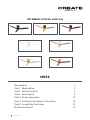
THIS MANUAL IS FOR ALL WINDCALM
Box contents 5
Step 1. Wood ceiling 6
Step 1. Concrete ceiling 7
Step 1. False ceiling 9
Step 2. Driver connection 10
Step 4. Anchoring the motor to the ceiling 12
Step 5. Assembling the blades 13
Blade balancing kit 14
WIND CALM

5ENGLISH
A B
E
CD
F G
H I J
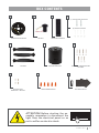
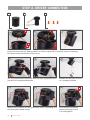
BOX CONTENTS
(1) EXPANSION SCREWS
MOUNTING BRACKET
WIRE CONNECTORS BALANCING KIT
BLADES
DRIVER
MOTOR BRACKET
REMOTE CONTROL
SCREWS + WASHERS FOR
BLADES
SCREWS FOR
BRACKET + MOTOR
(2) WOOD SCREWS
ATTENTION! Before starting the as-
sembly, remember to disconnect the
light from the electrical panel so as
not to suffer an electric shock.

6ENGLISH
+ +
D
x4
1
3
5
4
A
D2
A2
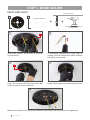
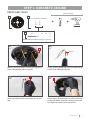
STEP 1. WOOD CEILING
(2) WOOD SCREWS
OPTIONAL ACCORDING TO
CEILING TYPE
If necessary, depending on the type of
ceiling, you will need to use a drill to make
the holes in the wood.
Repeat this step for the remaining 3 holes.Place the washer and then the screw D2
with the help of the screwdriver.
Make sure that piece A is perfectly hooked to the ceiling with the screws well tightened.
Mark with a pencil the 4 holes of piece A
on the ceiling.
PARTS AND TOOLS
NOT INCLUDED

7ENGLISH
A
D1
A
DA
Ø8 mm
1
3
2
4
+ +
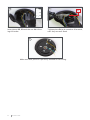
STEP 1. CONCRETE CEILING
(1) EXPANSION SCREWS
Using a drill, make the two corresponding
holes with a Ø8 mm drill bit.
Insert the pieces D1 in the holes of the ceil-
ing.
Place piece A matching its holes with the
screws D. Make sure the ceiling wires pass
through the center hole of piece A.
Mark 2 parallel holes on the ceiling with a
pencil using piece A as a guide.
D1 D2 D3 D4
Disassemble piece D separating it into pieces.
D
PARTS AND TOOLS
NOT INCLUDED

8ENGLISH
D4
D2
D3
D4
5 6
7
Insert piece D2, D3 and the nut D4 follow-
ing this order.
Tighten piece D4 with a number 10 wrench,
until they are well xed.
Make sure that piece A is perfectly hooked to the ceiling.

9ENGLISH
+ ++
A
A
X
1
3
5
4
2
PIECES AND TOOLS
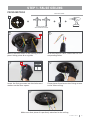
STEP 1. FALSE CEILING
FIXING SCREWS
WITH SPRING LEVER
NOT INCLUDED
Make sure that piece A is perfectly attached to the ceiling.
With the help of a drill, make the two cor-
responding holes.
Insert the xing screws into the holes and
make sure the lever opens.
Place piece A and screw the xing screws
to the false ceiling.
Mark 2 parallel holes on the ceiling with a
pencil using piece A as a guide.

10 ENGLISH
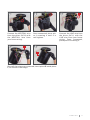
Join the connections of piece F with the ones in piece B, each
one with its corresponding color.
4
7
5
8
6
9
BF
Insert the hook you can nd in piece A in a hole in piece F so that the motor is hanging
to facilitate the connection of the wires.
AA
I
1 2 3
FF
Make sure the main structu-
re is properly placed.
Select and connect all the grounding wires, including the
one from your house wiring.
Once connected, place
piece I screwing it until
it is well tighten.
I
STEP 2. DRIVER CONNECTION

11ENGLISH
B
10
13
11
14
12
Connect the NEUTRAL wire
from the driver (AC-N) with
the NEUTRAL wire from
your house wiring.
Connect the LINE wire from
the driver (AC-L) with the
LINE wire from your house
wiring. Once connected,
place piece I screwing it.
Once connected, place pie-
ce I screwing it until it is
well tighten.
Once all the wires are connected, insert piece B inside piece
F, as shown in the image.
F
I

12 ENGLISH
+
AAA
H
H
FF
F
H
1 2 3
4
7
5
8
6
9
F
H
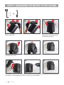
STEP 4. ANCHORING THE MOTOR TO THE CEILING
Use 2 screws H and screw them loosely into the parallel
holes in piece A.
Remove piece F from the hook
and snap it into piece A with-
out pinching any wire.
Once docked in the hole, turn piece F to the right and check that it is properly seated without
pinching any wires.
Once piece F is tted, t the 2 screws H into the remaining holes by tightening them with the
screwdriver. Then tighten the rst 2 screws to secure them.

13ENGLISH
4 5 6
E G
+
G
E
E
G
1 2 3
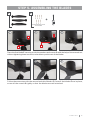
Follow the same step with the second and third blades E. Once all the blades E are in place,
screw all the screws G tightly so that the blades are well attached.
Place the rst blade E securing it with the washers and screws G with the help of the screwdriver,
without tightening them too much, to be able to put the rest of the blades.
STEP 5. ASSEMBLING THE BLADES
A replacement screw
is included

14 ENGLISH
BLADE BALANCING KIT
J
Your ceiling fan may have blade swing problems when in operation due to irregularities in
the blades or brackets. Also, incorrect system mounting or crooked bearings could cause
additional problems. The following procedure is recommended to remedy these problems:
1. Make sure the blades are rmly screwed to their brackets.
2. Make sure all blades are rmly secured to the center swivel casing and check the inclina-
tion of the blade mounts, they should all be the same.
3. Standing under the fan and looking up, check that none of the blade supports are bent so
that none of the blades are misplaced. You can correct the position of the blade holders by
gently bending them to the correct position.
4. You can check the height of the blades with a simple school ruler. Place the ruler against
the ceiling vertically and level with the outside of the blade tip. Check the distance from the
blade tip to the ceiling, carefully rotate the blades by hand and check the rest of the blades.
If the blades are not aligned, you can carefully bend the blade holder up or down slightly to
align with each other.
If the balance problem is not solved even by following the steps above, you must perform a
dynamic balance using the kit provided. Follow the procedure below:
1. Turn on the fan and set the speed at which the greatest sway is created (usually occurs at
the highest speed).
2. Turn off the fan. Select a blade and place the balancing clip, midway between the bracket
and the tip, on the rear edge of the blade.
3. Turn on the fan. Wait to see if the sway has improved or worsened. Turn the fan off again
and attach the clip to another blade to retest. Repeat this process with all the blades and
check which one has improved the most.
4. Place the clip on the blade that has improved the most. Move it in or out of the blade and
run the fan to nd the best position where the clip offers the greatest roll improvement.
5. Then remove the clip and install a balancing weight on top of the blade on the center line
near the point where the clip was placed. Use a knife or blade if necessary to separate the
weights.
Watch out: Stand at a safe distance from the blades. If the clip has not been properly se-
cured, for any reason, you could be injured.


16 ENGLISH
-
 1
1
-
 2
2
-
 3
3
-
 4
4
-
 5
5
-
 6
6
-
 7
7
-
 8
8
-
 9
9
-
 10
10
-
 11
11
-
 12
12
-
 13
13
-
 14
14
-
 15
15
-
 16
16


Create Wind Calm Ceiling Fan Instrukcja obsługi
- Typ
- Instrukcja obsługi
w innych językach
Inne dokumenty
-
GYMAX GYM09687 Instrukcja obsługi
-
Kompernass KH 1150 Instrukcja obsługi
-
Trane HFCF-SVX01A-EN Installation Operation & Maintenance
-
Yamaha S12 Instrukcja obsługi
-
Yamaha R2 Instrukcja obsługi
-
Yamaha VXS5 Instrukcja obsługi
-
-
Munters 14-24 AT Classic Instrukcja obsługi
-
-
Eglo SUSALE Instrukcja obsługi