
PS 200
Operating instructions en
ja
Instrukcja obsługi pl
Инструкция по зксплуатации ru
Kulllanma Talimat› tr
cn
ko
Printed: 07.07.2013 | Doc-Nr: PUB / 5070390 / 000 / 00

P
S2
0
0
F
e
r
ros
c
a
n
Gr
e
e
n
R
e
d
PSA93
161514
1312
6
1 2 3
4 5
8 9
10 11
7
Hi
l
t
i
.
O
u
t
pe
rf
or
m
.
O
u
t
l
as
t
.
R
e
v
ea
l
th
e
r
e
b
a
r
s
.
H
i
l
t
i
P
S
A
9
0
P
C
-
S
o
f
t
w
a
r
ea
n
dD
e
m
o
f
o
r
H
i
lt
i
P
S
2
0
0
F
e
rr
o
s
c
a
n
V
.
5
.
2
.
4
l
2
0
0
5
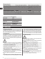
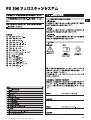
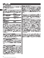
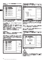
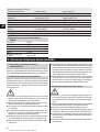
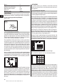
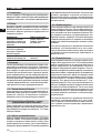
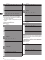
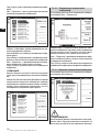
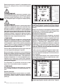
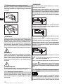
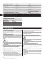
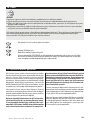
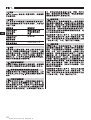
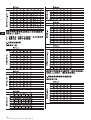
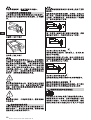
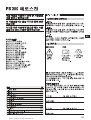
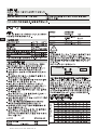
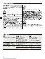
Hilti. Outperform. Outlast.
Reveal the rebars.
Hilti PSA90
PC-Software and Demo
for Hilti PS200 Ferroscan
1
Printed: 07.07.2013 | Doc-Nr: PUB / 5070390 / 000 / 00

1
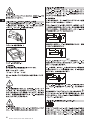
en
It is essential that the operating instructions
are read before the appliance is operated
for the first time.
Always keep these operating instructions
together with the appliance.
Ensure that the operating instructions are
with the appliance when it is given to other
persons.
PS 200 Ferroscan
1. General information
1.1 Safety notices and their meaning
-WARNING-
Draws attention to a potentially dangerous situation that
could lead to serious personal injury or fatality if the
instructions are not followed.
-CAUTION-
Draws attention to a potentially dangerous situation that
could lead to slight personal injury or damage to the
equipment or other property if the instructions are not
followed.
-NOTE-
Draws attention to an instruction or other useful infor-
mation.
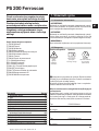
1.2 Pictograms
Contents Page
1. General information 1
2. Description 2
3. Items supplied 3
4. Technical data 4
5. Safety rules 8
6. Before use 10
7. Operation 11
8. Care and maintenance 32
9. Troubleshooting 32
10. Disposal 33
11. Manufacturer’s warranty – tools 33
12. EC declaration of conformity 34
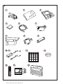
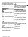
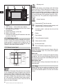
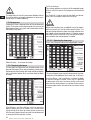
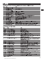
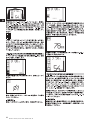
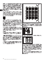
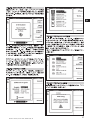
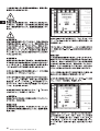
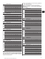
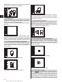
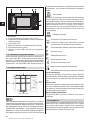
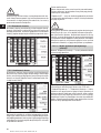
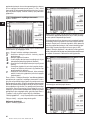
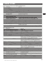
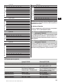
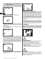
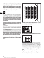
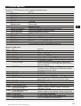
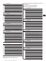
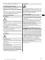
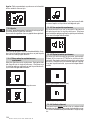
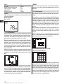
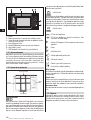
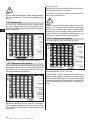
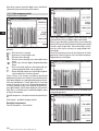
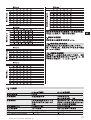
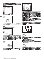
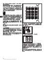
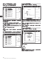
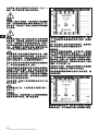
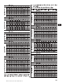
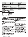
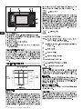
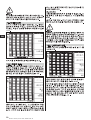
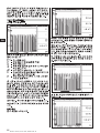
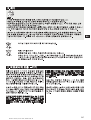
Components
햲 PS 200 S scanner
햳 PSA 60 soft pouch
햴 PS 200 M monitor
햵 PSA 94 memory card
햶 PSA 92 data cable
햷 PSA 93 headset with microphone
햸 PSA 61 soft pouch
햹 PSA 62 shoulder belt
햺 2 × PSA 80 battery
햻 2 × PUA 80 battery charger
햽 2 × supply cord
햾 PSA 10/11 reference grid set
햿 PUA 90 adhesive tape
헀 PUA 70 marking pen set
헁 PSA 90 PC software
헂 PS 200 toolbox
The numbers refer to the corresponding illustrations.
The illustrations can be found on the fold-out cover pages.
Keep these pages open while studying the operating
instructions.
In these operating instructions, the designation « the
appliance » always refers to the PS 200 Ferroscan sys-
tem.
Location of identification data on the appliance
The type designation and serial number can be found on
the type identification plate on the appliance. Make a note
of this data in your operating instructions and always
refer to it when contacting your Hilti representative or
service center.
Type: PS 200 S scanner
Serial no.:
Type: PS 200 M monitor
Serial no.:
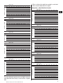
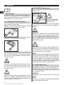
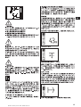
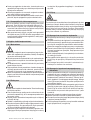
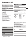
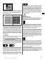
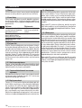
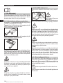
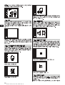
Warnings
General
warning
Read the
operating instructions
before use
Symbols
Return waste
material for
recycling
Printed: 07.07.2013 | Doc-Nr: PUB / 5070390 / 000 / 00

2
en
2. Description
2.1 Purpose
The PS 200 Ferroscan system is designed to be used
for localizing steel reinforcing bars and determining their
diameter and depth of cover.
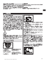
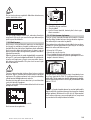
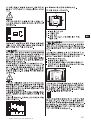
2.2 Overview
The appliance can be used for various concrete rein-
forcement detection applications. The scanning mode
used depends on the application. These fall broadly into
the following categories:
Application
Avoiding hitting reinforcing
bars when hammer drilling
or coring
Determining the position/
number and diameter of
reinforcing bars for checking
loading capacity
Determining depth of cover
over large areas
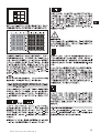
2.3 Operating principle
The system functions by running the scanner directly
over the surface of the structure. The data collected is
stored in the scanner until it can be transferred to the
monitor. The monitor is used for storing large amounts
of data, viewing the scans and also for evaluation of
results. The data can also be downloaded to a PC. The
PC software offers advanced evaluation options, data
archiving functions and the ability to quickly print out
complete reports.
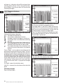
2.3.1 Quickscan detection
The scanner is run over the surface perpendicular to the
reinforcing bars. The position and approximate depth
of the reinforcing bars can be determined and marked
on the surface of the concrete.
2.3.2 Quickscan detection with accurate
determination of depth of cover
Before scanning, the operator is required to enter values
for the diameter of the reinforcing bars and the spacing
between the bars. The scanner is then used as described
in "2.3.1 Quickscan detection".
2.3.3 Quickscan recording
The scanner is used as in described in "2.3.2 Quickscan
detection". The data, however, is recorded while the scan-
ner moves over the surface. This data is then transferred
to the monitor where it can be evaluated and the average
depth of cover determined. If the data is downloaded to
a PC, this information can be evaluated, archived and a
report printed. Enhanced evaluation options allow Quick-
scans to be imported and evaluated automatically.
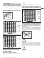
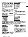
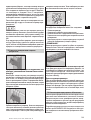
2.3.4 Imagescan
A reference grid is attached at the area of interest using
the adhesive tape supplied. After selecting the Images-
can mode with the scanner, the rows and columns of the
grid are scanned following the instructions on the screen.
The data is transferred to the monitor where the image
can be viewed and evaluated. The position of the rein-
forcing bars relative to the concrete surface is indicated.
The diameter of the bars and the depth of cover can be
determined.
If the data is downloaded to the PC application, this infor-
mation can be evaluated as on the Ferroscan monitor,
with the additional advantage of allowing a series of
points to be recorded along with associated depth and
diameter, archived and a report printed.
2.3.5 Blockscan
A reference grid is attached at the area of interest using
the adhesive tape supplied. After selecting Blockscan
mode, the user is prompted to select the first area to
scan. An Imagescan is then made. After completing the
Imagescan, the user is prompted to select the next area
to scan. This should be adjacent to the previous area.
Move the grid and then scan as before. This procedure
can be repeated for up to 3 × 3 Imagescans.The data is
transferred to the monitor. The Imagescans are auto-
matically stitched together to form a larger image. The
reinforcement layout can then be viewed over the whole
area. Individual Imagescans can be selected for evalu-
ation by "zooming in".
If the data is downloaded to the PC application, this
information can be evaluated as on the Ferroscan mon-
itor, with the additional advantage of allowing a series
of points to be recorded along with associated depth
and diameter, ar chived and a report printed.
Scanning mode
Quickscan detection,
Imagescan or Block-
scan
Imagescan
Quickscan recording
Printed: 07.07.2013 | Doc-Nr: PUB / 5070390 / 000 / 00

3
en
3. Items supplied
A complete PS 200 Ferroscan system consists of the following:
No. Designation
1 PS 200 S scanner
1 PSA 60 soft pouch
1 PS 200 M monitor
1 PSA 94 memory card
1 PSA 92 data cable
1 PSA 93 headset
with microphone
1 PSA 61 soft pouch
1 PSA 62 shoulder belt
2 PSA 80 batteries
2 PUA 80 chargers
2 Supply cords
2 PSA 10 reference grids
1 PUA 80 adhesive tape
1 PUA 70 marking pen
1 PSA 90 PC software
1 PS 200 toolbox
Accessories/spare parts
Item no. Designation
377654 PSA 10 reference grid set
340806 PUA 70 marking pen set
305141 PSA 91 memory card
319911 PSA 94 memory card
305142 PSA 92 data cable
319416 PSA 90 PC software
* PS 200 S scanner
* PS 200 S scanner set
377656 PSA 60 soft pouch
305144 PSA 63 hand strap
377658 PSA 62 shoulder strap
* PS 200 M monitor
377657 PSA 61 soft pouch
305143 PSA 93 headset with microphone
319362 PUA 90 adhesive tape
377660 PS 200 operating instructions
de/en/fr/it/es/nl/el/pt
377663 PS 200 operating instructions
en/ja/zh/ko/tr/pl/ru
377659 PS 200 toolbox
377472 PSA 80 battery
* PUA 80 charger
* Item number depends on country where item is ordered
Comments
*
Soft pouch for the scanner
*
Memory card (SD memory card)
USB cable
2.5 mm jack plug
Soft pouch for monitor
Belt for carrying the scanner and monitor in the soft pouches
NiMH rechargeable battery for the scanner or monitor
Charger for the PSA 80 battery
Supply cord for the PUA 80 charger *
Units in mm
3M Scotch tape 399 E, cotton tape for covering concrete
Set of 12 marking pens
PC software for the PS 200 Ferroscan system on CD-ROM
Plastic toolbox with insert for the PS 200 Ferroscan system
Comments
5 reference grids – mm
12 red marking pens
MMC card (128 MB)
SD card (at least 128 MB)
USB cable for transferring data
PC software on CD-ROM
Comprising PS 200 S scanner, PSA 80 battery, PSA 60
soft pouch, PSA 63 hand strap and operating instructions
in a cardboard box as replacement items
Comprising PS 200 S scanner, PSA 80 battery, PUA 80
charger, PSA 60 soft pouch, PSA 93 hand strap and
operating instructions in a Hilti toolbox
For the PS 200 S scanner
For the PS 200 S scanner
For carrying the PS 200 S scanner and PS 200 M monitor
Comprising PS 200 M monitor, PSA 80 battery, PSA 61
soft pouch and operating instructions in a cardboard box
as replacement items
For the PS 200 M monitor
For the PS 200 M monitor
Adhesive tape for attaching the reference grid to concrete
German, English, French, Italian, Spanish, Dutch, Greek,
Portuguese
English, Japanese, Chinese, Korean, Turkish, Polish,
Russian
With insert for the PS 200 system
For the PS 200 S scanner or PS 200 M monitor
For charging the PSA 80 battery
Printed: 07.07.2013 | Doc-Nr: PUB / 5070390 / 000 / 00

4
en
4. Technical data
-NOTE-
For PUA 80 charger, refer to PUA 80 charger operating
instructions.
4.1 Environmental
Operating temperature range
Storage temperature
Relative humidity (operation)
Dust and water protection
(operation)
Impact resistance
(appliance in toolbox)
Dropping
Vibration (not in operation)
4.2 System scanning performance
For reliable scanning results, the following conditions
must be fulfilled:
– Concrete surface smooth and flat.
– Reinforcement not corroded.
– Reinforcement lying parallel to concrete surface.
– Concrete does not contain additives or components
with magnetic properties.
– Reinforcing bars lying within ±5° of right angle to
direction of scan.
– Reinforcing bars are not welded.
– Neighboring bars are of similar diameter.
– Neighboring bars are at a similar depth.
– Accuracy specifications are valid only for the first
layer of reinforcement.
– No interfering influences from external magnetic
fields or objects nearby with magnetic properties.
– Bars have relative magnetic permeability of 85-105.
– The scanner wheels are clean and free from sand or
grit.
– All 4 scanner wheels rotate on when scanner is
moved across the object to be scanned.
– Bars comply with one of the following standards
(depends on PS 200 Ferroscan system item number
printed on underside of original toolbox).
Item number Standard
377638, 377639,
377645 DIN 488
377642 ASTM A 615/
A 615M-01b
377643 CAN/CSA-G30,
18-M92
377644 JIS G 3112
228001 GB 50010-2002
-WARNING-
If any one or more of these conditions are not fulfilled,
accuracy and precision may be compromised.
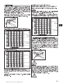
The ratio of bar spacing:cover (s:c) is often a limiting
factor in resolving individual bars.
This is defined as:
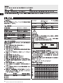
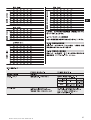
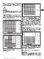
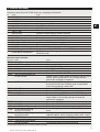
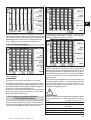
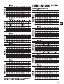
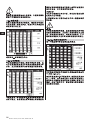
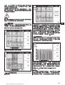
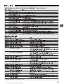
4.2.1 Detection range, measurement range and
accuracy
Minimum bar spacing of 36 mm (1.4 inches) for resolv-
ing individual bars or bar spacing:cover (s:c) 2:1, which-
ever is greater. A minimum depth of 10 mm (0.4 inch)
is required for a depth reading.
Minimum distance of nearest reinforcing bar from start-
ing point and finishing point of the scan (e.g. from edge
of reference grid): 30 mm (1.2 inch).
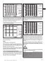
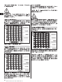
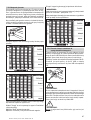
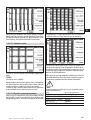
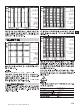
a. Imagescan and Blockscan
Rebar diameter given
Depth (mm)
20 40 60 80 100 120 140 160 180
6 ±2±3±3±4±50 X X X
8 ±2±2±3±4±50 0 X X
10 ±2 ±2 ±3 ±4 ±5 0 0 X X
12 ±2 ±2 ±3 ±4 ±5 ±10 0 X X
14 ±2 ±2 ±3 ±4 ±5 ±10 0 0 X
16 ±2 ±2 ±3 ±4 ±5 ±10 ±12 0 X
20 ±2 ±2 ±3 ±4 ±5 ±10 ±12 0 X
25 ±2 ±2 ±3 ±4 ±5 ±10 ±12 0 X
28 ±2 ±2 ±3 ±4 ±5 ±10 ±12 0 X
30 ±2 ±2 ±3 ±4 ±5 ±10 ±12 0 X
36 ±2 ±2 ±3 ±4 ±5 ±10 ±12 ±13 0
Spacing (s)
Surface
Depth of cover (c)
Bar diameter (DIN 488)
Wearing parts
The scanner wheels can be replaced by the user.
Item no. Designation
305152 PSW 200 S – 1 set of wheels
Refer to section 8.4 for instructions on removing and replacing the wheels.
Comments
4 wheels for the PS 200 S scanner, complete with hexagon
socket wrench (Allen key)
–10 °C to +50 °C
–20 °C to +60 °C
max. 90 %,
no condensation
IP54
EN 60068-2-29
EN 60068-2-32
MIL-STD 810 D
Origin/applicability of
the standard
European
Union
United States of
America
Canada
Japan
China
Printed: 07.07.2013 | Doc-Nr: PUB / 5070390 / 000 / 00

Depth (mm)
20 40 60 80 100 120 140 160 180
#3 ±2 ±2 ±3 ±4 ±5 0 0 X X
#4 ±2 ±2 ±3 ±4 ±5 ±10 0 X X
#5 ±2 ±2 ±3 ±4 ±5 ±10 ±12 0 X
#6 ±2 ±2 ±3 ±4 ±5 ±10 ±12 0 X
#7 ±2 ±2 ±3 ±4 ±5 ±10 ±12 0 X
#8 ±2 ±2 ±3 ±4 ±5 ±10 ±12 0 X
#9 ±2 ±2 ±3 ±4 ±5 ±10 ±12 0 X
#10 ±2 ±2 ±3 ±4 ±5 ±10 ±12 0 X
#11 ±2 ±2 ±3 ±4 ±5 ±10 ±12 ±13 0
Depth (inch)
0.8 1.6 2.4 3.1 3.9 4.7 5.5 6.3 7.1
#3 ±0.1 ±0.1 ±0.1 ±0.15 ±0.2 0 0 X X
#4 ±0.1 ±0.1 ±0.1 ±0.15 ±0.2 ±0.4 0 X X
#5 ±0.1 ±0.1 ±0.1 ±0.15 ±0.2 ±0.4 ±0.5 0 X
#6 ±0.1 ±0.1 ±0.1 ±0.15 ±0.2 ±0.4 ±0.5 0 X
#7 ±0.1 ±0.1 ±0.1 ±0.15 ±0.2 ±0.4 ±0.5 0 X
#8 ±0.1 ±0.1 ±0.1 ±0.15 ±0.2 ±0.4 ±0.5 0 X
#9 ±0.1 ±0.1 ±0.1 ±0.15 ±0.2 ±0.4 ±0.5 0 X
#10 ±0.1 ±0.1 ±0.1 ±0.15 ±0.2 ±0.4 ±0.5 0 X
#11 ±0.1 ±0.1 ±0.1 ±0.15 ±0.2 ±0.4 ±0.5 ±0.5 0
Depth (mm)
20 40 60 80 100 120 140 160 180
#10 ±2 ±2 ±3 ±4 ±5 0 0 X X
#15 ±2 ±2 ±3 ±4 ±5 ±10 ±12 0 X
#20 ±2 ±2 ±3 ±4 ±5 ±10 ±12 0 X
#25 ±2 ±2 ±3 ±4 ±5 ±10 ±12 0 X
#30 ±2 ±2 ±3 ±4 ±5 ±10 ±12 0 X
#35 ±2 ±2 ±3 ±4 ±5 ±10 ±12 ±13 0
Depth (mm)
20 40 60 80 100 120 140 160 180
6 ±2±3±3±4±50 X X X
10 ±2 ±2 ±3 ±4 ±5 0 0 X X
13 ±2 ±2 ±3 ±4 ±5 ±10 0 X X
16 ±2 ±2 ±3 ±4 ±5 ±10 ±12 0 X
19 ±2 ±2 ±3 ±4 ±5 ±10 ±12 0 X
22 ±2 ±2 ±3 ±4 ±5 ±10 ±12 0 X
25 ±2 ±2 ±3 ±4 ±5 ±10 ±12 0 X
29 ±2 ±2 ±3 ±4 ±5 ±10 ±12 0 X
32 ±2 ±2 ±3 ±4 ±5 ±10 ±12 0 X
35 ±2 ±2 ±3 ±4 ±5 ±10 ±12 ±13 0
38 ±2 ±2 ±3 ±4 ±5 ±10 ±12 ±13 0
Depth (mm)
20 40 60 80 100 120 140 160 180
8 ±2±3±3±4±50 X X X
10 ±2 ±2 ±3 ±4 ±5 0 0 X X
12 ±2 ±2 ±3 ±4 ±5 ±10 0 X X
14 ±2 ±2 ±3 ±4 ±5 ±10 ±12 0 X
16 ±2 ±2 ±3 ±4 ±5 ±10 ±12 0 X
18 ±2 ±2 ±3 ±4 ±5 ±10 ±12 0 X
20 ±2 ±2 ±3 ±4 ±5 ±10 ±12 0 X
22 ±2 ±2 ±3 ±4 ±5 ±10 ±12 0 X
25 ±2 ±2 ±3 ±4 ±5 ±10 ±12 0 X
28 ±2 ±2 ±3 ±4 ±5 ±10 ±12 ±13 0
32 ±2 ±2 ±3 ±4 ±5 ±10 ±12 ±13 0
36 ±2 ±2 ±3 ±4 ±5 ±10 ±12 ±13 0
The value indicates typical accuracy of depth measure-
ment (deviation from actual) in mm or inches, as applic-
able.
O: Bar is visible at this depth but no depth is calculated.
X: Bar cannot be detected at this depth.
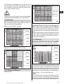
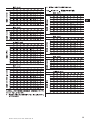
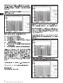
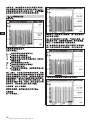
Imagescan – rebar diameter not given.
Depth (mm)
20 40 60 80 100 120 140 160 180
6 ±3±3±4±6±80 X X X
8 ±3±3±4±6±80 0 X X
10 ±3 ±3 ±4 ±6 ±8 0 0 X X
12 ±3 ±3 ±4 ±6 ±8 ±12 0 X X
14 ±3 ±3 ±4 ±6 ±8 ±12 0 0 X
16 ±3 ±3 ±4 ±6 ±8 ±12 ±14 0 X
20 ±3 ±3 ±4 ±6 ±8 ±12 ±14 0 X
25 ±3 ±3 ±4 ±6 ±8 ±12 ±14 0 X
28 ±3 ±3 ±4 ±6 ±8 ±12 ±14 0 X
30 ±3 ±3 ±4 ±6 ±8 ±12 ±14 0 X
36 ±3 ±3 ±4 ±6 ±8 ±12 ±14 ±16 0
Depth (mm)
20 40 60 80 100 120 140 160 180
#3 ±3 ±3 ±4 ±6 ±8 0 0 X X
#4 ±3 ±3 ±4 ±6 ±8 ±12 0 X X
#5 ±3 ±3 ±4 ±6 ±8 ±12 ±14 0 X
#6 ±3 ±3 ±4 ±6 ±8 ±12 ±14 0 X
#7 ±3 ±3 ±4 ±6 ±8 ±12 ±14 0 X
#8 ±3 ±3 ±4 ±6 ±8 ±12 ±14 0 X
#9 ±3 ±3 ±4 ±6 ±8 ±12 ±14 0 X
#10 ±3 ±3 ±4 ±6 ±8 ±12 ±14 0 X
#11 ±3 ±3 ±4 ±6 ±8 ±12 ±14 ±16 X
Depth (inch)
0.8 1.6 2.4 3.1 3.9 4.7 5.5 6.3 7.1
#3 ±0.1 ±0.1 ±0.2 ±0.2 ±0.3 0 0 X X
#4 ±0.1 ±0.1 ±0.2 ±0.2 ±0.3 ±0.4 0 X X
#5 ±0.1 ±0.1 ±0.2 ±0.2 ±0.3 ±0.4 ±0.6 0 X
#6 ±0.1 ±0.1 ±0.2 ±0.2 ±0.3 ±0.4 ±0.6 0 X
#7 ±0.1 ±0.1 ±0.2 ±0.2 ±0.3 ±0.4 ±0.6 0 X
#8 ±0.1 ±0.1 ±0.2 ±0.2 ±0.3 ±0.4 ±0.6 0 X
#9 ±0.1 ±0.1 ±0.2 ±0.2 ±0.3 ±0.4 ±0.6 0 X
#10 ±0.1 ±0.1 ±0.2 ±0.2 ±0.3 ±0.4 ±0.6 0 X
#11 ±0.1 ±0.1 ±0.2 ±0.2 ±0.3 ±0.4 ±0.6 ±0.6 X
Depth (mm)
20 40 60 80 100 120 140 160 180
#10 ±3 ±3 ±4 ±6 ±8 0 0 X X
#15 ±3 ±3 ±4 ±6 ±8 ±12 ±14 0 X
#20 ±3 ±3 ±4 ±6 ±8 ±12 ±14 0 X
#25 ±3 ±3 ±4 ±6 ±8 ±12 ±14 0 X
#30 ±3 ±3 ±4 ±6 ±8 ±12 ±14 0 X
#35 ±3 ±3 ±4 ±6 ±8 ±12 ±14 ±16 X
Depth (mm)
20 40 60 80 100 120 140 160 180
6 ±3±3±4±6±80 X X X
10 ±3 ±3 ±4 ±6 ±8 0 0 X X
13 ±3 ±3 ±4 ±6 ±8 ±12 0 X X
16 ±3 ±3 ±4 ±6 ±8 ±12 ±14 0 X
19 ±3 ±3 ±4 ±6 ±8 ±12 ±14 0 X
22 ±3 ±3 ±4 ±6 ±8 ±12 ±14 0 X
25 ±3 ±3 ±4 ±6 ±8 ±12 ±14 0 X
29 ±3 ±3 ±4 ±6 ±8 ±12 ±14 0 X
32 ±3 ±3 ±4 ±6 ±8 ±12 ±14 0 X
35 ±3 ±3 ±4 ±6 ±8 ±12 ±14 ±16 X
38 ±3 ±3 ±4 ±6 ±8 ±12 ±14 ±16 X
5
en
Bar diameter (ASTM)Bar diameter (ASTM)Bar diameter (CAN)Bar diameter (JIS)
Bar diameter (DIN 488)Bar diameter (ASTM)Bar diameter (ASTM)Bar diameter (CAN)Bar diameter (JIS)
Bar diameter (GB 50010-2002)
Printed: 07.07.2013 | Doc-Nr: PUB / 5070390 / 000 / 00

6
en
Depth (mm)
20 40 60 80 100 120 140 160 180
8 ±3±3±4±6±80 X X X
10 ±3 ±3 ±4 ±6 ±8 0 0 X X
12 ±3 ±3 ±4 ±6 ±8 ±12 0 X X
14 ±3 ±3 ±4 ±6 ±8 ±12 ±14 0 X
16 ±3 ±3 ±4 ±6 ±8 ±12 ±14 0 X
18 ±3 ±3 ±4 ±6 ±8 ±12 ±14 0 X
20 ±3 ±3 ±4 ±6 ±8 ±12 ±14 0 X
22 ±3 ±3 ±4 ±6 ±8 ±12 ±14 0 X
25 ±3 ±3 ±4 ±6 ±8 ±12 ±14 0 X
28 ±3 ±3 ±4 ±6 ±8 ±12 ±14 ±16 X
32 ±3 ±3 ±4 ±6 ±8 ±12 ±14 ±16 X
36 ±3 ±3 ±4 ±6 ±8 ±12 ±14 ±16 X
Value indicates typical accuracy of depth measurement
(deviation from actual) in mm or inches, as applicable.
O: Bar is visible at this depth but no depth is calculated.
X: Bar cannot be detected at this depth.
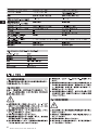
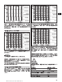
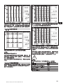
b. Quickscan recording
Diameter is known.
Depth (mm)
20 40 50 60 80 100
6 ±1±1±2±2±4±5
8 ±1±1±2±2±4±5
10 ±1 ±1 ±2 ±2 ±4 ±5
12 ±1 ±1 ±2 ±2 ±4 ±5
14 ±1 ±1 ±2 ±2 ±4 ±5
16 ±1 ±1 ±2 ±2 ±4 ±5
20 ±1 ±1 ±2 ±2 ±4 ±5
25 ±1 ±1 ±2 ±2 ±4 ±5
28 ±1 ±1 ±2 ±2 ±4 ±5
30 ±1 ±1 ±2 ±2 ±4 ±5
36 ±1 ±1 ±2 ±2 ±4 ±5
Depth (mm)
20 40 50 60 80 100
#3 ±1 ±1 ±2 ±2 ±4 ±5
#4 ±1 ±1 ±2 ±2 ±4 ±5
#5 ±1 ±1 ±2 ±2 ±4 ±5
#6 ±1 ±1 ±2 ±2 ±4 ±5
#7 ±1 ±1 ±2 ±2 ±4 ±5
#8 ±1 ±1 ±2 ±2 ±4 ±5
#9 ±1 ±1 ±2 ±2 ±4 ±5
#10 ±1 ±1 ±2 ±2 ±4 ±5
#11 ±1 ±1 ±2 ±2 ±4 ±5
Depth (inch)
0.8 1.6 2.0 2.4 3.1 3.9
#3 ±0.05 ±0.05 ±0.1 ±0.1 ±0.15 ±0.2
#4 ±0.05 ±0.05 ±0.1 ±0.1 ±0.15 ±0.2
#5 ±0.05 ±0.05 ±0.1 ±0.1 ±0.15 ±0.2
#6 ±0.05 ±0.05 ±0.1 ±0.1 ±0.15 ±0.2
#7 ±0.05 ±0.05 ±0.1 ±0.1 ±0.15 ±0.2
#8 ±0.05 ±0.05 ±0.1 ±0.1 ±0.15 ±0.2
#9 ±0.05 ±0.05 ±0.1 ±0.1 ±0.15 ±0.2
#10 ±0.05 ±0.05 ±0.1 ±0.1 ±0.15 ±0.2
#11 ±0.05 ±0.05 ±0.1 ±0.1 ±0.15 ±0.2
Depth (mm)
20 40 50 60 80 100
#10 ±1 ±1 ±2 ±2 ±4 ±5
#15 ±1 ±1 ±2 ±2 ±4 ±5
#20 ±1 ±1 ±2 ±2 ±4 ±5
#25 ±1 ±1 ±2 ±2 ±4 ±5
#30 ±1 ±1 ±2 ±2 ±4 ±5
#35 ±1 ±1 ±2 ±2 ±4 ±5
Depth (mm)
20 40 50 60 80 100
6 ±1±1±2±2±4±5
10 ±1 ±1 ±2 ±2 ±4 ±5
13 ±1 ±1 ±2 ±2 ±4 ±5
16 ±1 ±1 ±2 ±2 ±4 ±5
19 ±1 ±1 ±2 ±2 ±4 ±5
22 ±1 ±1 ±2 ±2 ±4 ±5
25 ±1 ±1 ±2 ±2 ±4 ±5
29 ±1 ±1 ±2 ±2 ±4 ±5
32 ±1 ±1 ±2 ±2 ±4 ±5
35 ±1 ±1 ±2 ±2 ±4 ±5
38 ±1 ±1 ±2 ±2 ±4 ±5
Depth (mm)
20 40 50 60 80 100
8 ±1±1±2±2±4±5
10 ±1 ±1 ±2 ±2 ±4 ±5
12 ±1 ±1 ±2 ±2 ±4 ±5
14 ±1 ±1 ±2 ±2 ±4 ±5
16 ±1 ±1 ±2 ±2 ±4 ±5
18 ±1 ±1 ±2 ±2 ±4 ±5
20 ±1 ±1 ±2 ±2 ±4 ±5
22 ±1 ±1 ±2 ±2 ±4 ±5
25 ±1 ±1 ±2 ±2 ±4 ±5
28 ±1 ±1 ±2 ±2 ±4 ±5
32 ±1 ±1 ±2 ±2 ±4 ±5
36 ±1 ±1 ±2 ±2 ±4 ±5
Value indicates typical accuracy of depth measurement
(deviation from actual) in mm or inches as applicable.
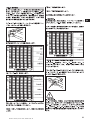
c. Quickscan detection with depth measurement
Diameter is known.
Depth (mm)
20 40 50 60 80 100
6 ±2±2±2±3±4±5
8 ±2±2±2±3±4±5
10 ±2 ±2 ±2 ±3 ±4 ±5
12 ±2 ±2 ±2 ±3 ±4 ±5
14 ±2 ±2 ±2 ±3 ±4 ±5
16 ±2 ±2 ±2 ±3 ±4 ±5
20 ±2 ±2 ±2 ±3 ±4 ±5
25 ±2 ±2 ±2 ±3 ±4 ±5
28 ±2 ±2 ±2 ±3 ±4 ±5
30 ±2 ±2 ±2 ±3 ±4 ±5
36 ±2 ±2 ±2 ±3 ±4 ±5
Bar diameter (DIN 488)Bar diameter (ASTM) Bar diameter (ASTM) Bar diameter (GB 50010-2002)
Bar diameter (CAN)Bar diameter (JIS)Bar diameter (DIN 488) Bar diameter (GB 50010-2002)
Printed: 07.07.2013 | Doc-Nr: PUB / 5070390 / 000 / 00

7
en
4.3 Specifications
Maximum scanning speed
Memory type
Memory capacity
Screen type/size
Screen resolution
Dimensions
Weight (with PSA 80 battery)
Depth (mm)
20 40 50 60 80 100
#3 ±2 ±2 ±2 ±3 ±4 ±5
#4 ±2 ±2 ±2 ±3 ±4 ±5
#5 ±2 ±2 ±2 ±3 ±4 ±5
#6 ±2 ±2 ±2 ±3 ±4 ±5
#7 ±2 ±2 ±2 ±3 ±4 ±5
#8 ±2 ±2 ±2 ±3 ±4 ±5
#9 ±2 ±2 ±2 ±3 ±4 ±5
#10 ±2 ±2 ±2 ±3 ±4 ±5
#11 ±2 ±2 ±2 ±3 ±4 ±5
Depth (inch)
0.8 1.6 2.0 2.4 3.1 3.9
#3 ±0.1 ±0.1 ±0.1 ±0.1 ±0.15 ±0.2
#4 ±0.1 ±0.1 ±0.1 ±0.1 ±0.15 ±0.2
#5 ±0.1 ±0.1 ±0.1 ±0.1 ±0.15 ±0.2
#6 ±0.1 ±0.1 ±0.1 ±0.1 ±0.15 ±0.2
#7 ±0.1 ±0.1 ±0.1 ±0.1 ±0.15 ±0.2
#8 ±0.1 ±0.1 ±0.1 ±0.1 ±0.15 ±0.2
#9 ±0.1 ±0.1 ±0.1 ±0.1 ±0.15 ±0.2
#10 ±0.1 ±0.1 ±0.1 ±0.1 ±0.15 ±0.2
#11 ±0.1 ±0.1 ±0.1 ±0.1 ±0.15 ±0.2
Depth (mm)
20 40 50 60 80 100
#10 ±2 ±2 ±2 ±3 ±4 ±5
#15 ±2 ±2 ±2 ±3 ±4 ±5
#20 ±2 ±2 ±2 ±3 ±4 ±5
#25 ±2 ±2 ±2 ±3 ±4 ±5
#30 ±2 ±2 ±2 ±3 ±4 ±5
#35 ±2 ±2 ±2 ±3 ±4 ±5
Depth (mm)
20 40 50 60 80 100
6 ±2±2±2±3±4±5
10 ±2 ±2 ±2 ±3 ±4 ±5
13 ±2 ±2 ±2 ±3 ±4 ±5
16 ±2 ±2 ±2 ±3 ±4 ±5
19 ±2 ±2 ±2 ±3 ±4 ±5
22 ±2 ±2 ±2 ±3 ±4 ±5
25 ±2 ±2 ±2 ±3 ±4 ±5
29 ±2 ±2 ±2 ±3 ±4 ±5
32 ±2 ±2 ±2 ±3 ±4 ±5
35 ±2 ±2 ±2 ±3 ±4 ±5
38 ±2 ±2 ±2 ±3 ±4 ±5
Depth (mm)
20 40 50 60 80 100
8 ±2±2±2±3±4±5
10 ±2 ±2 ±2 ±3 ±4 ±5
12 ±2 ±2 ±2 ±3 ±4 ±5
14 ±2 ±2 ±2 ±3 ±4 ±5
16 ±2 ±2 ±2 ±3 ±4 ±5
18 ±2 ±2 ±2 ±3 ±4 ±5
20 ±2 ±2 ±2 ±3 ±4 ±5
22 ±2 ±2 ±2 ±3 ±4 ±5
25 ±2 ±2 ±2 ±3 ±4 ±5
28 ±2 ±2 ±2 ±3 ±4 ±5
32 ±2 ±2 ±2 ±3 ±4 ±5
36 ±2 ±2 ±2 ±3 ±4 ±5
Value indicates typical accuracy of depth measurement
(deviation from actual) in mm or inches as applicable.
d. Quickscan detection
Depth measurement is typically accurate to within ±10 %
of the effective depth.
4.2.2 Accuracy of bar diameter measurement
±1 standard diameter when rebar spacing: depth of cover
≥2 :1. Bar diameter measurement is possible only at
depths of up to 60 mm.
4.2.3 Accuracy of rebar location
Relative bar center measurement accuracy (all modes),
typical: T ypically ±3 mm or typically ±0.1 inch relative to
the measured position, when the bar spacing: depth of
cover ≥1.5 :1.
Bar diameter (ASTM)Bar diameter (ASTM)Bar diameter
(CAN)
Bar diameter (JIS)
Bar diameter (GB 50010-2002)
PS 200 M monitor
--
Removable SD card, max. memory
card size: 1 GB
At least 150 Imagescans or 75 Quick-
scans (total 2250 m), plus up to
15 minutes of speech with 32 MB
card.
LCD/115 × 86 mm
320 × 240 pixels/16 gray scales
264 × 152 × 57 mm
1.40 kg
PS 200 S scanner
0.5 m/s
Built-in data flash memory
9 Imagescans plus up to 30 m
of recorded Quickscan
(max. 10 scans)
LCD/50 × 37 mm
128 × 64 pixels
260 × 132 × 132 mm
1.40 kg
Printed: 07.07.2013 | Doc-Nr: PUB / 5070390 / 000 / 00

8
en
5. Safety rules
5.1 General safety rules
In addition to the safety rules listed in the individual sec-
tions of these operating instructions, the following rules
must be strictly observed at all times.
5.2 Intended use
The appliance is intended to be used for locating rein-
forcing bars in concrete, measuring depth of concrete
cover and estimating the diameter of the bars in the
uppermost layer in accordance with the specifications
detailed in section 4.
● Dangerous situations may occur when the appliance
is either not used for its intended purpose or is used
incorrectly by untrained personnel.
● To minimize the risk of injury, use only genuine Hilti
accessories and replacement parts.
● Tampering with the appliance or modification of its
parts is not permissible.
● Take notice of the instructions regarding use, care and
maintenance given in the operating instructions.
● Do not deactivate any safety devices. Do not remove
any information or warning labels.
● Have the appliance repaired only at a Hilti service cen-
ter.
● In particularly critical situations where measurements
have safety and structural stability implications, always
check results by removing material from the surface
of the structure and physically checking the position,
depth and diameter of reinforcement at key positions.
● When drilling at or near to a bar indicated by the appli-
ance, never drill deeper than the bar depth indicated.
5.3 Work area safety
● Ensure there are no objects in the area of work with
which you could injure yourself.
● Keep other people away from the work area, especially
children.
● Avoid working in awkward body positions.
● Wear footwear with a non-slip tread and ensure you
always employ a stable standing position.
● Avoid leaning when working on ladders. Always work
from a secure position and stay in balance.
● Use the appliance only within its defined performance
limits.
● Check with a qualified person that it is safe to drill at
a specified point before beginning drilling.
● Never use the appliance in areas where there is dan-
ger of explosion.
● Ensure the toolbox is properly secured during trans-
port and does not pose a risk of injury .
Minimum battery life
(with PSA 80 battery)
Automatic power-off
Backup battery type/life
PC connection
Headset connection
Scanner -monitor data interface
Scanner -monitor data transfer time
Infrared range
Infrared output power
4.4 Technical data for PSA 80 battery
Battery type NiMH
Nominal voltage 9.6 V nominal
Capacity 2000 mAh nominal
Dimensions 42 × 46 × 46 mm or
5.6 × 1.8 × 1.8 in
Weight 0.3 kg or 0.7 lb
Min. no. charge cycles Typically 500
8 hours under typical conditions
5 min. after last press of a button
Lithium/10 years (typically)
--
--
Infrared
<16 s for 9 images, <2 s for 1 image
0.3 m (typically)
Max. 500 mW
8 hours under typical conditions
Set by the user
Lithium/10 years (typically)
USB V 1.1
2.5 mm mini jack
Infrared
<16 s for 9 images, <2 s for 1 image
0.3 m (typically)
Max. 500 mW
Printed: 07.07.2013 | Doc-Nr: PUB / 5070390 / 000 / 00

9
en
5.3.1 Electromagnetic compatibility
Although the appliance fulfills the requirements of the
relevant regulations, Hilti cannot rule out the possibili-
ty that:
● Other equipment (e.g. airborne navigation systems,
medical equipment) will be disturbed by the PS 200
or
● That this disturbance will lead to a malfunction of the
PS 200. In such cases or in case of any uncertainty ,
control measurements must be carried out.
5.4 General safety measures
5.4.1 Mechanical
● Check the appliance for possible faults before use.
In case of a fault, have the appliance repaired by Hilti
Service.
● If the appliance is dropped or subjected to an impact,
its accuracy must be subsequently checked.
● Check the accuracy of the appliance each time before
use.
● When moving the appliance between temperature
extremes, allow it to become acclimatize to the new
temperature before use.
● Even though the appliance is protected against the
ingress of moisture, always wipe it dry before storing
it in the toolbox.
5.4.2 Electrical
● Avoid shorting the battery terminals. Such electrical
shorting can cause fire.
● Ensure that the exterior surfaces of the battery are
clean and dry before connecting it to the charger.
● Use only the battery specified in these operating
instructions.
● Ensure that the battery is safely disposed of at the end
of its life.
● When transporting the appliance or storing it for a
longer period of time, remove the batter y. Before
reusing it, inspect the batter y for any signs of leak-
age or damage.
● To avoid environmental pollution, the battery must be
disposed of in accordance with country-specific reg-
ulations. In case of doubt, contact Hilti.
5.4.3 Liquids
-WARNING-
A corrosive liquid can leak from defective batteries.
Avoid contact with this liquid. Should the liquid come
into contact with the skin, wash the area affected liber-
ally with soap and water. In case of contact with the
eyes, rinse them immediately with water and consult a
doctor.
5.5 Requirements to be met by the user
● The appliance is intended for professional users.
● The appliance may be used, maintained and cared for
only by authorized, personnel who have recieved
instruction in its use. This personnel must be specially
instructed in the hazards associated with the appli-
ance.
● Always concentrate on your work. Always think care-
fully about what you are doing. Do not use the appli-
ance if you are unable to concentrate.
● Do not use the appliance if it appears to be defective
in any way.
● If you are unsure of any scan results, consult a Hilti
specialist before proceeding.
● Observe all warning and information messages dis-
played by the scanner and monitor.
5.6 Scanning requirements and limitations
● Always check the accuracy of the appliance before
commencing work on structures where measurements
have safety and structural stability implications. Scan
a reinforcing bar of known location, depth and diam-
eter and check the results against the accuracy spe-
cifications.
● Do not use the PS 200 S scanner if the wheels do not
turn freely or appear to be worn. Contact Hilti for repair
information. Additionally , you can clean or replace the
wheels – refer to section 8.
● Check the settings made in the appliance before use.
● Apply only light pressure to the scanner when mov-
ing it across the surface.
● Reinforcement that lies beneath the uppermost layer
of reinforcement may not be detected.
● Remove all items such as rings, bracelets, etc. before
commencing scanning.
Printed: 07.07.2013 | Doc-Nr: PUB / 5070390 / 000 / 00

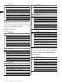
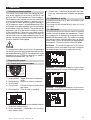
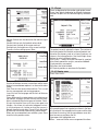
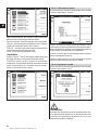
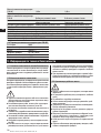
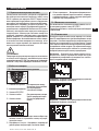
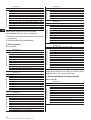
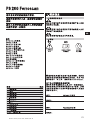
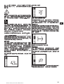
6.2 PSA 91/PSA 94 memory card
Insert the memory card in the slot provided on the back
of the monitor.
To remove the memory card, press it once. The card will
release from the slot. It can now be easily gripped and
removed.
-WARNING-
Although the memory card is of the SD or Multimedia
Card type, standards vary between different manufac-
turers. To help ensure data security and integrity, mem-
ory cards supplied by Hilti should be used. Data may be
irretrievably lost if memory cards other than those sup-
plied by Hilti are used.
-WARNING-
Do not remove the memory card during operation or
when the monitor is switched on. Removing the card at
such a time may result in data loss. Only remove the
card when the monitor is switched off.
-NOTE-
When the memory card is removed, the monitor will auto-
matically revert to using the 3 MB internal memory . Data
will then be saved in this memory under a project with
the name "Prj00001" until a memory card is inserted in
the monitor. When a memory card is inserted and the
monitor switched on, all data in internal memory will be
transferred to the memory card automatically.
6.2.1 Using memory cards
With monitors with item no. 319281, only memory cards
of the MMC type may be used (up to a max. capacity of
128 MB). With monitors with item no. 31225, memory
cards of the MMC and SD types may be used (up to a
max. capacity of 1 GB).
-WARNING-
SD memory cards cannot be used with the old-type
monitor.
-NOTE-
The item no. can be found on the type identification plate
on the underside of the monitor.
10
en
6. Operation
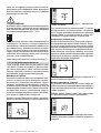
6.1 PSA 80 battery
Charge both batteries using the PUA 80 chargers. Full
instructions are contained in the PUA 80 charger oper-
ating instructions. Before first use, the batteries must
be charged for 14 hours continuously.
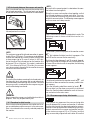
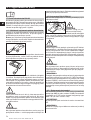
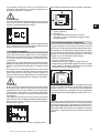
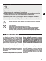
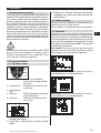
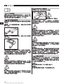
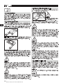
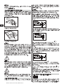
6.1.1 Inserting and removing the battery
Check that the battery is correctly aligned with the scan-
ner or monitor as shown below.
Scanner – With the battery end cap facing you, the large
groove on the battery should be on the left.
Monitor – With the battery end cap facing you, the large
groove on the battery should be on the right.
Push the battery into the opening as far as it will go. T urn
the end cap clockwise until it slots into place and snaps
tight. To remove the battery, turn the end cap anti-clock-
wise as far as it will go. Withdraw the battery from the
scanner or monitor.
-CAUTION-
The battery should slide easily into the scanner or mon-
itor. Do not force the battery into the scanner or moni-
tor as this may damage the battery itself or the scanner
or monitor casing.
-WARNING-
Do not remove the battery during operation or when the
monitor is switched on. Removing the battery at such
a time may result in data loss. Remove the battery only
when the monitor is switched off.
PS 200
Fer
r
os
can
-CAUTION-
Take care to ensure that
the card is inserted the
right way round.
Printed: 07.07.2013 | Doc-Nr: PUB / 5070390 / 000 / 00

11
en
7. Operation
7.1 Carrying and using the system
The scanner can be used without the monitor for scan-
ning, or the monitor can be carried in the PSA 61 soft
pouch on the PSA 60 shoulder belt. The first option is
advantageous when working in areas that are difficult
to access and maximum mobility is required, such as
on a scaffold or ladder. When the scanner memory is
full (9 Imagescans made, 1 complete Blockscan or 30 m
of Quickscan have been recorded), the user must return
to the monitor to transfer the data. The monitor can be
kept nearby (e.g. at the foot of the scaffold, in a vehicle,
in the site office etc.). When the user intends to make
more scans than the scanner is capable of storing in its
memory and wishes to avoid repeated journeys to the
monitor, the monitor can be attached to a belt or carried
using the shoulder strap supplied.
-CAUTION-
The temperature inside a vehicle that is left exposed to
the heat of the sun can easily exceed the maximum stor-
age temperature for the PS 200. Damage to one or more
components of the PS 200 may occur if it is stored in
temperatures exceeding 60 °C or 158 °F.
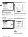
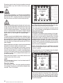
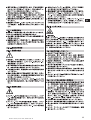
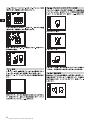
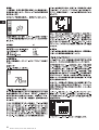
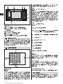
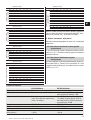
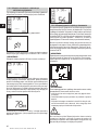
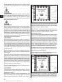
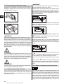
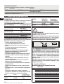
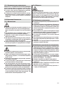
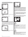
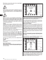
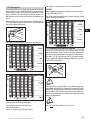
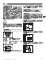
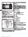
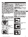
7.2 Operating the scanner
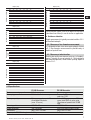
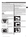
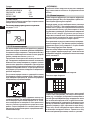
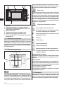
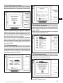
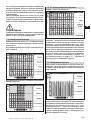
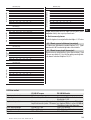
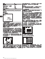
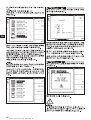
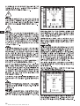
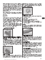
7.2.1 Control panel and screen layout
1–Arrow buttons
2–Confirm button
3–On/off button
4–Cancel button
5–Record button
1 – Menu area. Functions that can be selected using the
Arrow and Confirm buttons
2 – Status information – information such as battery
level, memory status
13
2
1
2
3
4
5
3 – Variable area – information displayed is user feed-
back – e.g. measuring mode, bar depth, scan progress
etc.
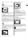
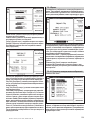
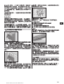
7.2.2 Switching on and off
To switch the scanner on or off, press and hold the On/off
button momentarily.
The scanner can be switched off only when it is in the
main menu.
7.2.3 Main menu
The system always starts in the main menu. All scanning
functions and set-up options are selected here. The bat-
terychargestatusisdisplayedatthetopofthescreen
together with the memory status. The various scan modes
and settings menus are displayed as icons on the left
side of screen. Use the Arrow buttons to toggle between
these options. The Confirm button selects the option.
Quickscan – The remaining memory for Quickscan
recording is shown at the top of the screen in meters or
feet (depending on the scanner type and units set).
Imagescan – The number of Imagescans in the scanner,
up to a maximum of 9, is shown at the top of the screen.
Blockscan – The number of Imagescans in the scanner,
up to a maximum of 9, is shown at the top of the screen.
Toggle up or down in options or
values.
Confirms a value or a selection.
Cancels an input or moves back
one screen.
Starts or stops a recording.
Printed: 07.07.2013 | Doc-Nr: PUB / 5070390 / 000 / 00

12
en
Settings – Sets various parameters and deletes all scans
held in memory.
7.2.4 Settings
Use this menu to set general parameters and to delete
scans from the scanner that have not been transferred
to the monitor.
Upon entering Settings, the following screen is dis-
played:
Use the Arrow buttons to toggle between options, Con-
firm to select an option and Cancel to return to the main
menu.
7.2.4.1 Set display backlight
Sets the display backlight. Use the Arrow buttons to tog-
gle between options. Use the Confirm button to select
the desired option and then press the Cancel button to
return to the settings menu.
Backlight permanently on
Backlight permanently off
Backlight timed – switches off 5 minutes after the last
press of a button. Backlight activates automatically on
next press of a button.
7.2.4.2 Set volume
Sets the volume level of the audible signal during scan-
ning. Use the Arrow buttons to toggle between options.
Use the Confirm button to select the desired option and
then press the Cancel button to return to the settings
menu.
7.2.4.3 Set units
Sets the units used during measurement. This is avail-
able only in units with item no. 377642. Use the Arrow
buttons to toggle between options. Use the Confirm but-
ton to select the desired option and then press the Can-
cel button to return to the Settings menu.
metric (mm or m, as appropriate)
imperial (inches or feet, as appropriate)
7.2.4.4 Delete data
Deletes all
data contained in the scanner. This function
can be accessed only if data is contained in memory. If
data is contained in memory , the bar that appears next
Printed: 07.07.2013 | Doc-Nr: PUB / 5070390 / 000 / 00

13
en
to the diskette symbol is filled. If not, the bar is shown
empty.
-WARNING-
This may result in permanent data loss. Data that has
not been transferred to the monitor will be permanently
deleted.
Press the Down arrow button and then the Confirm
button to delete data. Alternatively, press the Cancel
button to return to the Settings menu.
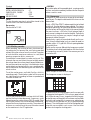
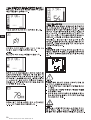
7.2.5 Quickscan
Quickscan can be used to quickly detect bar positions
and depths that are then subsequently marked on the
surface. This is procedure is named Quickscan detec-
tion.
Accurate depth measurement is another Quickscan func-
tion in which values for bar diameter and bar spacing
must be previously entered.
Alternatively, the data can be recorded and evaluated on
the monitor or in the PC application.In this way, the aver-
age depth of cover over the reinforcement over large
stretches of the surface can be easily determined. This
is termed Quickscan recording.
-CAUTION-
The scanner only detects reinforcing bars that lie per-
pendicular to the direction of travel. Bars that lie parallel
to the direction of travel will not be detected. Therefore,
ensure that the object is scanned in both the horizontal
and vertical directions.
An incorrect depth may be calculated for bars that lie diag-
onal to the direction of travel.
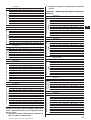
Switch on the scanner. The Quickscan icon is automati-
cally the first selected.
Select Quickscan from the main menu.
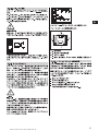
The Quickscan screen is then displayed.
1 – Bar depth
2 – Distance traveled
3 – Signal strength
4 – Settings: minimum depth, scan direction, bar
diameter, bar spacing
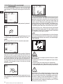
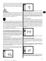
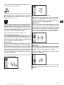
7.2.5.1 Quickscan detection
Move the scanner over the surface. Reinfor cing bars that
lie perpendicular to the direction of travel will be detect-
ed. The distance covered by the scanner is recorded.
When approaching a reinforcing bar, the signal strength
increases and depth values may appear in the display.
When at the center of a reinforcing bar:
– the red LED lights,
– the scanner beeps,
– the signal strength bar is at maximum,
– and the approximate depth of the bar is indicated
(lowest depth value indicated = center of the bar).
The bar is positioned along the center line of the scanner
and may be marked on the surface using a PUA 70 mark-
er . The accuracy of the depth measurement can be increased
by switching to accurate depth measurement measuring
mode. Please refer to section 7.2.5.2.
This symbol may appear when the scanner is moved over
the surface. It indicates that the scanner is being moved
too quickly to be able to process all signals generated. The
maximum speed is 0.5m/s (20 inches/sec.). If the symbol
appears during Quickscan detection, press Confirm and
scan again.
1
2
3
4
Printed: 07.07.2013 | Doc-Nr: PUB / 5070390 / 000 / 00

14
en
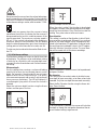
7.2.5.2 Quickscan with accurate depth
measurement
The measuring mode "Quickscan with accurate depth
measurement" is selected by pressing the Confirm but-
ton.
The diameter must be known and previously entered.
In addition, the value for the spacing between bars must
also be entered if it lies between >36 and <120 mm.
-NOTE-
Bar spacing of 36 mm or less cannot be measured.
This can be calculated automatically using the Quickscan
detection function by searching for the center of the bar
and pressing the red Record button when the scanner
is over the mid point of the bar. Next, search for the mid
point of the next bar and again press the Record but-
ton. Bar spacing is then calculated automatically and
recorded. If the spacing is known, the value can also be
entered manually.
After setting the bar diameter and bar spacing, the scan-
ning procedure is identical to the procedure described
at 7.2.5.1.
7.2.5.3 Quickscan recording
To record the position and depth of all reinforcing bars
detected, place the scanner on the surface and use
Quickscan detection to find a position where there are
no bars present. Mark the starting point with a PUA 70
marker and press the Record button. The diskette sym-
bol appears on the screen, indicating that the scanner
is recording data. Move the scanner over the surface.
At the end of the scan, take care to ensure that the end
point is not directly over a rebar. T o stop recording, press
Record again. Use a PUA 70 marker to mark the end of
the stretch that has been scanned.
-NOTE-
Reinforcing bars that lie perpendicular to the direction
of travel will be detected and automatically recorded.
Ensure that the settings are correctly set before begin-
ning recording.
-WARNING-
Always carry out an Imagescan prior to Quickscan record-
inginorderto:
– establish the direction of the uppermost layer of rein-
forcement,
– minimize the risk of measuring on a spliced bar,
– and immediately see if there are any ferrous materials
in the concrete that may affect the accuracy of the result.
-CAUTION-
Do not press Record before placing the scanner at the
point where the scanning should begin. Failure to do
this may result in incorrect or misleading measurements.
Up to 30 m (98 ft) can be recorded before it is neces-
sary to transfer the data to the monitor. It is also possi-
ble to record several separate stretches (max. 10) that
add up to a maximum of 30 m.
Printed: 07.07.2013 | Doc-Nr: PUB / 5070390 / 000 / 00

15
en
-WARNING-
Do not remove the scanner from the surface before stop-
ping the recording or setting a marker. Failure to do this
may result in incorrect or misleading measurements. For
information on setting a marker, refer to section 7.2.5.5.
This symbol may appear when the scanner is being
moved over the surface. It indicates that the scanner is
being moved too fast and it is unable to process all the
signals generated. The maximum scanning speed is
0.5 m/s. If the symbol is displayed while recording a
Quickscan, press the Confirm button. You will need to
begin the recording operation again from the original
starting point or from where the last marker was set.
The data may be transferred to the monitor . Refer to sec-
tion 7.4.
7.2.5.4 Quickscan settings
The Quickscan settings are shown on the left hand side
of the display . The settings can be made before making
a Quickscan or a Quickscan with accurate depth mea-
surement. Use the Arrow buttons and Confirm to access
the setting.
Minimum depth
Use this setting when scanning a surface and looking
specifically for bars that are located above a certain
depth. For example, if checking for 40 mm minimum
depth of cover, set the value to 40 mm. (For quality
assurance measurements add an extra 2 mm to account
for any accuracy limitations). The LED will light only if
a reinforcing bar lying within 40 mm of the surface is
detected.
Select the minimum depth function using the Arrow
buttons and then press Confirm.
Setting minimum depth
Minimum depth function disabled
When the value is set to 0, the function is deactivated
and appears as above. Enter the required minimum depth
using the Arrow buttons. Press Confirm to make the
setting. The system returns to the main menu.
Scan direction
This setting is used to set the direction in which Quick-
scan recording is performed. Although it has no direct
effect on any measurement values subsequently con-
tained in the monitor or PC application, it helps to match
the resulting chart and depth values in the PC applica-
tion with the actual structure surface. The scan direc-
tion will be saved with all Quickscan recordings.
Select the direction in which the scan is to be performed
and press Confirm.
Bar diameter
This setting must be made in order to be able to mea-
sure depth of cover accurately, or to allow values to be
recorded. Only then can depth be measured accurately .
Select the Bar Diameter function using the Arrow but-
tons. Press Confirm.
If no bar diameter is selected, the scanner will calculate
the depth as though the average bar diameter of the rel-
evant standard setting range were set.
Printed: 07.07.2013 | Doc-Nr: PUB / 5070390 / 000 / 00

16
en
Standard ∅
DIN 488 16 mm
ASTM A 615/A 615M-01b # 7
CAN/CSA-G30, 18-M92 C 20
JIS G 3112 D 22
GB 50012-2002 18 mm
-NOTE-
The bar diameter previously set will be stored in the
scanner after it has been switched off.
Bar spacing
Please refer to 7.2.5.2.
7.2.5.5 Setting a marker
When recording, the surfaces of many structures con-
tain obstacles that prevent the scan being recorded
without lifting the scanner from the surface. Examples
of such obstacles are piers or columns in a wall, door
openings, expansion joints, corners etc.
If an obstacle is encountered, a marker may be set. This
interrupts the scan and allows the user to safely remove
the scanner from the surface, place it beyond the obstruc-
tion and then continue scanning. It also indicates where
certain objects are located within a scan, providing addi-
tional information for referencing the scan data to the
actual surface.
To set the marker press and hold Confirm, whilst in
recording mode. The diskette symbol will be crossed
out, indicating that recording has been suspended and
a marker has been set.
Then lift the scanner from the surface whilst still hold-
ing the Confirm button depressed. If necessary, mark
the position on the surface using a PUA 70 marker. Place
the scanner back on the surface beyond the obstacle,
release Confirm and continue scanning. The marker will
be shown as a vertical line in the scan data when viewed
on the monitor or in the PC application.
-CAUTION-
De to interruption of the recorded signal, scanning results
are less accurate immediately before and after the point
where a mark is made.
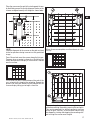
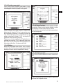
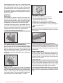
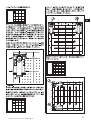
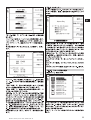
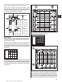
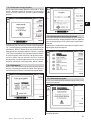
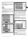
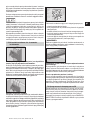
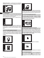
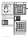
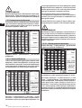
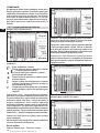
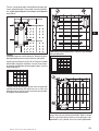
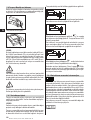
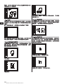
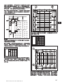
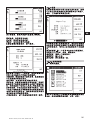
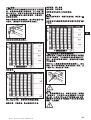
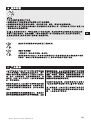
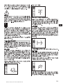
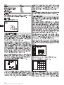
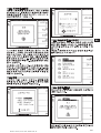
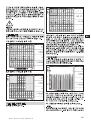
7.2.6 Imagescan
Imagescan is used to create an image of the reinforce-
ment layout. The depth and diameter of the bars can be
determined.
Firstly, a PSA 10 or PSA 11 reference grid has to be fixed
to the wall. Use the adhesive tape supplied. This tape is
designed specifically for sticking to concrete structures
and can be torn off the roll by hand at the correct length.
For most surfaces, a 100 mm (4 inch) piece of tape at
each corner is adequate to secure the grid. Particularly
moist or dusty surfaces may require a length of tape
along each side of the grid.
Alternatively, a grid can be marked directly on the sur -
face. Using a straight edge (such as a piece of wood) as
a guide, mark a 4 × 4 grid with 150 mm spacing between
the parallel lines.
Switch on the scanner. Move to the Imagescan symbol.
The battery level is displayed together with the number
of Imagescans currently held in the memory out of a
maximum of 9.
Select Imagescan from the main menu.
The Imagescan screen is displayed.
A representation of the grid appears on the screen with
a suggested starting point. This is always upper left and
will suffice for most scans. Image data will only be gen-
erated for areas of the grid that have been scanned both
vertically and horizontally. In some cases, obstacles on
the scan area may prevent this (e.g. a pipe penetrating
a beam). The starting point can then be changed to opti-
mize the area scanned in such a case. Use the Arrow
buttons to change the starting point.
Printed: 07.07.2013 | Doc-Nr: PUB / 5070390 / 000 / 00

17
en
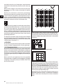
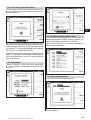
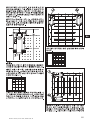
Place the scanner on the grid at the starting point shown
by the blinking arrow. Ensure the alignment marks on the
scanner are aligned correctly with the grid as shown below .
-NOTE-
Incorrect alignment of the scanner on the grid may lead
to the bar positions being incorrect on the generated
image.
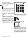
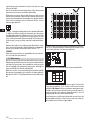
Press Record and move the scanner along the first row .
Progress when scanning is shown by a thick black line
which advances on the display as the scanner is moved
over the surface.
The scanner will emit a double beep at the end of the
row, automatically stopping the recording. Repeat the
process for each row, observing the prompts on the
scanner display telling you to begin a new line.
150
150
5
1
2
®
PS 200 S Ferroscan
®
PS 200 S Ferroscan
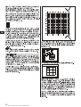
When all rows are complete, scan the columns in a sim-
ilar way.
The recording of any row or column may be interrupt-
ed before reaching the end by pressing Record again.
This may be required if an obstacle prevents scanning
of the full path. Similarly, an entire row or column may
be skipped by starting and stopping the recording with-
out running the scanner over the grid.
®
PS 200 S Ferroscan
®
PS 200 S Ferroscan
®
PS200 S Ferroscan
®
PS200 S Ferroscan
Printed: 07.07.2013 | Doc-Nr: PUB / 5070390 / 000 / 00

18
en
Note that no image will be created for areas of the grid
that are not scanned in both directions.
It is possible to repeat the previous row or column by
pressing Cancel. This may be necessary if the user is
not sure that the scan field has not been followed accu-
rately. Pressing Cancel a second time aborts the scan
and returns to the main menu.
This symbol may appear when the scanner is being
moved over the surface. It indicates that the scanner is
being moved too quickly to allow it to process all the
signals generated. The maximum speed is 0.5 m/s or
20 inch/s. If this symbol appears, press Confirm and
repeat the row or column you were scanning. In all cas-
es, move the scanner more slowly over the surface.
When the scan is complete, press the Confirm button
to return to the main menu. The data may be transferred
to the monitor for viewing and evaluation. Please refer
to section 7.4.
-CAUTION-
Pressing the Cancel button causes the recorded Images-
can to be deleted. The screen then returns to the main
menu.
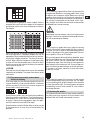
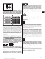
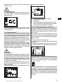
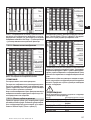
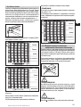
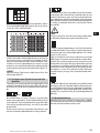
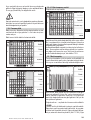
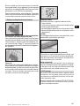
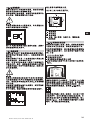
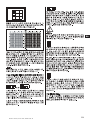
7.2.7 Blockscan
Blockscan automatically stitches Imagescans together
to give an impression of the reinforcement layout over
a large area. The exact bar position, depth and diame-
ter can also be determined on the monitor by selecting
each Imagescan individually.
Attach the reference grid in the same way as when mak-
ing an Imagescan. Mark the edge(s) for the transition
to the next grid using a PUA 70 marker , as shown below.
Switch on the scanner. Move to the Blockscan symbol.
The battery level is given, together with the number of
Imagescans currently held in the memory out of a max-
imum of 9.
To begin, select Blockscan from the main menu.
A representation of a Blockscan is shown on the screen.
Each square represents an Imagescan. Up to 3 × 3 Image-
scans can be scanned. Select the position of the first
Imagescan that you will make in the series using the
Arrow buttons.PressConfirm to begin the first Image-
scan. Note that the coordinates of any points on the
Blockscan will be referenced from the upper left corner.
Refer to the previous section for details on how to car-
ry out the Imagescan. When the Imagescan is complete,
the system returns to the Blockscan screen.
150
150
300
450
600
300 450 600
5 6 7 8
1
2
3
4
Printed: 07.07.2013 | Doc-Nr: PUB / 5070390 / 000 / 00
Strona się ładuje...
Strona się ładuje...
Strona się ładuje...
Strona się ładuje...
Strona się ładuje...
Strona się ładuje...
Strona się ładuje...
Strona się ładuje...
Strona się ładuje...
Strona się ładuje...
Strona się ładuje...
Strona się ładuje...
Strona się ładuje...
Strona się ładuje...
Strona się ładuje...
Strona się ładuje...
Strona się ładuje...
Strona się ładuje...
Strona się ładuje...
Strona się ładuje...
Strona się ładuje...
Strona się ładuje...
Strona się ładuje...
Strona się ładuje...
Strona się ładuje...
Strona się ładuje...
Strona się ładuje...
Strona się ładuje...
Strona się ładuje...
Strona się ładuje...
Strona się ładuje...
Strona się ładuje...
Strona się ładuje...
Strona się ładuje...
Strona się ładuje...
Strona się ładuje...
Strona się ładuje...
Strona się ładuje...
Strona się ładuje...
Strona się ładuje...
Strona się ładuje...
Strona się ładuje...
Strona się ładuje...
Strona się ładuje...
Strona się ładuje...
Strona się ładuje...
Strona się ładuje...
Strona się ładuje...
Strona się ładuje...
Strona się ładuje...
Strona się ładuje...
Strona się ładuje...
Strona się ładuje...
Strona się ładuje...
Strona się ładuje...
Strona się ładuje...
Strona się ładuje...
Strona się ładuje...
Strona się ładuje...
Strona się ładuje...
Strona się ładuje...
Strona się ładuje...
Strona się ładuje...
Strona się ładuje...
Strona się ładuje...
Strona się ładuje...
Strona się ładuje...
Strona się ładuje...
Strona się ładuje...
Strona się ładuje...
Strona się ładuje...
Strona się ładuje...
Strona się ładuje...
Strona się ładuje...
Strona się ładuje...
Strona się ładuje...
Strona się ładuje...
Strona się ładuje...
Strona się ładuje...
Strona się ładuje...
Strona się ładuje...
Strona się ładuje...
Strona się ładuje...
Strona się ładuje...
Strona się ładuje...
Strona się ładuje...
Strona się ładuje...
Strona się ładuje...
Strona się ładuje...
Strona się ładuje...
Strona się ładuje...
Strona się ładuje...
Strona się ładuje...
Strona się ładuje...
Strona się ładuje...
Strona się ładuje...
Strona się ładuje...
Strona się ładuje...
Strona się ładuje...
Strona się ładuje...
Strona się ładuje...
Strona się ładuje...
Strona się ładuje...
Strona się ładuje...
Strona się ładuje...
Strona się ładuje...
Strona się ładuje...
Strona się ładuje...
Strona się ładuje...
Strona się ładuje...
Strona się ładuje...
Strona się ładuje...
Strona się ładuje...
Strona się ładuje...
Strona się ładuje...
Strona się ładuje...
Strona się ładuje...
Strona się ładuje...
Strona się ładuje...
Strona się ładuje...
Strona się ładuje...
Strona się ładuje...
Strona się ładuje...
Strona się ładuje...
Strona się ładuje...
Strona się ładuje...
Strona się ładuje...
Strona się ładuje...
Strona się ładuje...
Strona się ładuje...
Strona się ładuje...
Strona się ładuje...
Strona się ładuje...
Strona się ładuje...
Strona się ładuje...
Strona się ładuje...
Strona się ładuje...
Strona się ładuje...
Strona się ładuje...
Strona się ładuje...
Strona się ładuje...
Strona się ładuje...
Strona się ładuje...
Strona się ładuje...
Strona się ładuje...
Strona się ładuje...
Strona się ładuje...
Strona się ładuje...
Strona się ładuje...
Strona się ładuje...
Strona się ładuje...
Strona się ładuje...
Strona się ładuje...
Strona się ładuje...
Strona się ładuje...
Strona się ładuje...
Strona się ładuje...
Strona się ładuje...
Strona się ładuje...
Strona się ładuje...
Strona się ładuje...
Strona się ładuje...
Strona się ładuje...
Strona się ładuje...
Strona się ładuje...
Strona się ładuje...
Strona się ładuje...
Strona się ładuje...
Strona się ładuje...
Strona się ładuje...
Strona się ładuje...
Strona się ładuje...
Strona się ładuje...
Strona się ładuje...
Strona się ładuje...
Strona się ładuje...
Strona się ładuje...
Strona się ładuje...
Strona się ładuje...
Strona się ładuje...
Strona się ładuje...
Strona się ładuje...
Strona się ładuje...
Strona się ładuje...
Strona się ładuje...
Strona się ładuje...
Strona się ładuje...
Strona się ładuje...
Strona się ładuje...
Strona się ładuje...
Strona się ładuje...
Strona się ładuje...
Strona się ładuje...
Strona się ładuje...
Strona się ładuje...
Strona się ładuje...
Strona się ładuje...
Strona się ładuje...
Strona się ładuje...
Strona się ładuje...
Strona się ładuje...
Strona się ładuje...
Strona się ładuje...
Strona się ładuje...
Strona się ładuje...
Strona się ładuje...
Strona się ładuje...
Strona się ładuje...
Strona się ładuje...
Strona się ładuje...
Strona się ładuje...
Strona się ładuje...
Strona się ładuje...
Strona się ładuje...
Strona się ładuje...
Strona się ładuje...
Strona się ładuje...
Strona się ładuje...
Strona się ładuje...
Strona się ładuje...
Strona się ładuje...
Strona się ładuje...
Strona się ładuje...
-
 1
1
-
 2
2
-
 3
3
-
 4
4
-
 5
5
-
 6
6
-
 7
7
-
 8
8
-
 9
9
-
 10
10
-
 11
11
-
 12
12
-
 13
13
-
 14
14
-
 15
15
-
 16
16
-
 17
17
-
 18
18
-
 19
19
-
 20
20
-
 21
21
-
 22
22
-
 23
23
-
 24
24
-
 25
25
-
 26
26
-
 27
27
-
 28
28
-
 29
29
-
 30
30
-
 31
31
-
 32
32
-
 33
33
-
 34
34
-
 35
35
-
 36
36
-
 37
37
-
 38
38
-
 39
39
-
 40
40
-
 41
41
-
 42
42
-
 43
43
-
 44
44
-
 45
45
-
 46
46
-
 47
47
-
 48
48
-
 49
49
-
 50
50
-
 51
51
-
 52
52
-
 53
53
-
 54
54
-
 55
55
-
 56
56
-
 57
57
-
 58
58
-
 59
59
-
 60
60
-
 61
61
-
 62
62
-
 63
63
-
 64
64
-
 65
65
-
 66
66
-
 67
67
-
 68
68
-
 69
69
-
 70
70
-
 71
71
-
 72
72
-
 73
73
-
 74
74
-
 75
75
-
 76
76
-
 77
77
-
 78
78
-
 79
79
-
 80
80
-
 81
81
-
 82
82
-
 83
83
-
 84
84
-
 85
85
-
 86
86
-
 87
87
-
 88
88
-
 89
89
-
 90
90
-
 91
91
-
 92
92
-
 93
93
-
 94
94
-
 95
95
-
 96
96
-
 97
97
-
 98
98
-
 99
99
-
 100
100
-
 101
101
-
 102
102
-
 103
103
-
 104
104
-
 105
105
-
 106
106
-
 107
107
-
 108
108
-
 109
109
-
 110
110
-
 111
111
-
 112
112
-
 113
113
-
 114
114
-
 115
115
-
 116
116
-
 117
117
-
 118
118
-
 119
119
-
 120
120
-
 121
121
-
 122
122
-
 123
123
-
 124
124
-
 125
125
-
 126
126
-
 127
127
-
 128
128
-
 129
129
-
 130
130
-
 131
131
-
 132
132
-
 133
133
-
 134
134
-
 135
135
-
 136
136
-
 137
137
-
 138
138
-
 139
139
-
 140
140
-
 141
141
-
 142
142
-
 143
143
-
 144
144
-
 145
145
-
 146
146
-
 147
147
-
 148
148
-
 149
149
-
 150
150
-
 151
151
-
 152
152
-
 153
153
-
 154
154
-
 155
155
-
 156
156
-
 157
157
-
 158
158
-
 159
159
-
 160
160
-
 161
161
-
 162
162
-
 163
163
-
 164
164
-
 165
165
-
 166
166
-
 167
167
-
 168
168
-
 169
169
-
 170
170
-
 171
171
-
 172
172
-
 173
173
-
 174
174
-
 175
175
-
 176
176
-
 177
177
-
 178
178
-
 179
179
-
 180
180
-
 181
181
-
 182
182
-
 183
183
-
 184
184
-
 185
185
-
 186
186
-
 187
187
-
 188
188
-
 189
189
-
 190
190
-
 191
191
-
 192
192
-
 193
193
-
 194
194
-
 195
195
-
 196
196
-
 197
197
-
 198
198
-
 199
199
-
 200
200
-
 201
201
-
 202
202
-
 203
203
-
 204
204
-
 205
205
-
 206
206
-
 207
207
-
 208
208
-
 209
209
-
 210
210
-
 211
211
-
 212
212
-
 213
213
-
 214
214
-
 215
215
-
 216
216
-
 217
217
-
 218
218
-
 219
219
-
 220
220
-
 221
221
-
 222
222
-
 223
223
-
 224
224
-
 225
225
-
 226
226
-
 227
227
-
 228
228
-
 229
229
-
 230
230
-
 231
231
-
 232
232
-
 233
233
-
 234
234
-
 235
235
-
 236
236
-
 237
237
-
 238
238
-
 239
239
-
 240
240
-
 241
241
-
 242
242
-
 243
243


w innych językach
Powiązane artykuły
-
Hilti PS 200 Instrukcja obsługi
-
-
-
-
-
Hilti PS 1000 Instrukcja obsługi
-
-
-
Hilti psa 200 Instrukcja obsługi
-