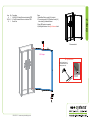
Classic Exhibits ECO-1059 Setup Instructions
- Typ
- Setup Instructions

866.463.2611 • www.ecosystemsdisplays.com
Setups
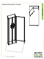
Order #XXXXX - ECO-2059 Sustainable Exhibit - 10’x10’ Conguration
Plan View
10’
10’

866.463.2611 • www.ecosystemsdisplays.com
General Info
7A
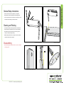
General Setup Instructions
•The setup instructions are created specifically for your configuration.
•Setup instructions are laid out sequentially in levels, including exploded
views and a logical series of steps for assembly. We encourage you to study
the instructions before attempting to assemble your exhibit.
Hex Tool for Assembling Exhibit Extrusion Lock Connectors
Numbering Instructions for Setups/Packing Inline Connection between Extrusions Baseplate Connection for Vertical Extrusions
Cleaning and Packing
•Use non-abrasive cleaners when cleaning extrusions or ECO Glass inserts.
•Use mild cleaners and soft materials such as cotton to clean all laminates.
•Keep exhibit components away form extreme heat and long exposure to
sun light. This will prevent warping and fading.
•Retain all packing material for ease of re-packing. This protects the exhibit
components and keeps each part organized.
Disassembling
•When disassembling exhibit, tighten all setscrews to prevent loss of hardware
in the shipping process.

866.463.2611 • www.ecosystemsdisplays.com
General Info
124 5
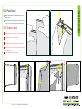
SEG Graphic Install
1
2
3
4
Graphic is installed corners first. This allows a proportional fit around the
perimeter of the extrusion.
Locate channels along the edge of the extrusions.
Fold over graphic (hiding threads) and tuck silicon edge and fabric
into corners.
After corners are complete, slide in the rest of the graphic into channel.
(From edges to center)
3
5Graphic is installed. Stand back and be amazed!
Place ECO panel together with a vertical offset, slide down to lock
connector in place.
Panel Corner Connectors are installed just like ECO panels. Remove by
off-setting top lock clips horizontally followed by separating vertically.
2
1
ECO Panel Install 12

866.463.2611 • www.ecosystemsdisplays.com
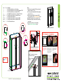
Step 1
When partly assembled
Steps:
1) Attach lower horizontals [5,7,8] & door threshold
between verticals [1,2,3,4].
2) Connect upper horizontals [5A,6,7A,8A] between
verticals [1,2,3,4].
3) Attach verticals [9A,9B] to horizontals [8,8A],
using screw caps. See Vertical Attachment detail.
4) Apply SEG graphics to front, right side & door.
5) Attach backer graphic to back side of assembly
using Velcro.
6) Install Monitor Mount to verticals [9,9A].
See Monitor Mount Attachment detail.
Item
1
2
3
4
5/5A
6
7/7A
8/8A
9/9A
Qty.
1
1
1
1
1/1
1
1/1
1/1
1/1
Description
96”h S44 Vertical Extrusion w/ Door Hinge
96”h S44 Vertical Extrusion w/ Door Stop & attached TSP3
96”h S44 Vertical Extrusion w/ attached TSP3
96”h RSG520 Vertical Extrusion w/ attached TSP3 & S11
54”w Z45 Horizontal Extrusion w/ attached Velcro
24”w Z45 Horizontal Extrusion
24”w Z45 Horizontal Extrusion w/ attached TSP3
54”w Z45 Horizontal Extrusion w/ attached TSP3
96”h Z45 Vertical Extrusion
1
2
3
4
9A
5
5A
Door
Threshold
Velcro
7
68A
7A
Top View
Top View
S44
S44
S44
Door
Stop
Door Hinge
TSP3
TSP3
TSP3
TSP3
RSG520 S11
TSP3
Top View
Top View
8
9B
Vertical Attachment
*
Insert V4 connectors into groove
of horizontal extrusion.
Tighten set screw
to secure.
V4
set
screw Screw
cap
Graphic Removal
To remove the graphic from
the frame, locate the fabric
pull tab. Gently pull up on the
tab to remove the fabric.
Step 1
Insert corner A. Turn edge of
graphic so silicon welt is
perpendicular to face of
graphic. Insert narrow side
of welt with fabric to outside
into the channel. Repeat for
other side of this corner.
Step 2
Repeat Step 1 for opposite
corner C, then insert corner
B, followed by corner D, to
complete the installation of
the corners.
Step 3
Once all corners are inserted,
press one silicon edge into
channel from corners and
work toward the center.
Make sure welt is fully inserted
into channel. Continue until
all sides are done. Smooth
out edges of graphic.
SEG Graphic Installation
It is important to first insert
graphic into each alternate
corner then to the sides of
the frame. If this is not done,
graphic will not fit into the
frame correctly.
Corner A
Corner D
Corner B
Corner C
*
*
**
*
D
o
o
r
Attach monitor mount to Vertical extrusions
using standoff barrels, bolts and wing nuts.
Note: Mount installs over SEG graphic.
*Monitor Mount Attachment
Bolts
Monitor
Mount
Stand-Off
Barrels
Wing
Nuts
S
E
G Graphic

866.463.2611 • www.ecosystemsdisplays.com
Step 2
When assembled
4
Steps:
1) Attach Base Plate to vertical [14] using bolt.
2) Connect horizontals [15,15A] between vertical [14]
and vertical [4] of assembled closet.
3) Apply SEG graphic to assembly.
4) Install lights as shown. See Light Attachment detail.
Item
14
15/15A
19
Qty.
1
1/1
1
Description
88.583”h Z45 Vertical Extrusion w/ attached TSP3
66”w Z45 Horizontal Extrusion w/ attached TSP3
Base Plate
15A
15
14
SEG G
r
a
phi
c
19
*
*
Lock Clip into Groove of
Horizontal Extrusion, then
slide Light onto Clip.
Light Attachment
Slide light into light
receiving hardware
Lock into
groove of
horizontal
-
 1
1
-
 2
2
-
 3
3
-
 4
4
-
 5
5


Classic Exhibits ECO-1059 Setup Instructions
- Typ
- Setup Instructions
w innych językach
- English: Classic Exhibits ECO-1059
Powiązane artykuły
-
Classic Exhibits ECO-1050 Setup Instructions
-
-
-
-
-
-
-
-
-
Inne dokumenty
-
Displays2go GK2013 Instrukcja obsługi
-
-
Blaze 0606 instrukcja
-
Blaze 0604 instrukcja
-
Makita LS1040S Instrukcja obsługi
-
Makita LS1440 Instrukcja obsługi
-
 Little Tikes Endless Adventures Lookout Swing Set Instrukcja obsługi
-
Makita LS1018 Instrukcja obsługi
-
