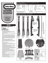
Classic Exhibits ECO-2067 Setup Instructions
- Typ
- Setup Instructions

866.463.2611 • www.ecosystemsdisplays.com
Setups
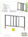
Order #XXXXX - ECO-2067 Sustainable Exhibit - 10’x20’ Conguration
Plan View
10’
20’

866.463.2611 • www.ecosystemsdisplays.com
General Info
7A
General Setup Instructions
•The setup instructions are created specifically for your configuration.
•Setup instructions are laid out sequentially in levels, including exploded
views and a logical series of steps for assembly. We encourage you to study
the instructions before attempting to assemble your exhibit.
Hex Tool for Assembling Exhibit Extrusion Lock Connectors
Numbering Instructions for Setups/Packing Inline Connection between Extrusions Baseplate Connection for Vertical Extrusions
Cleaning and Packing
•Use non-abrasive cleaners when cleaning extrusions or ECO Glass inserts.
•Use mild cleaners and soft materials such as cotton to clean all laminates.
•Keep exhibit components away form extreme heat and long exposure to
sun light. This will prevent warping and fading.
•Retain all packing material for ease of re-packing. This protects the exhibit
components and keeps each part organized.
Disassembling
•When disassembling exhibit, tighten all setscrews to prevent loss of hardware
in the shipping process.

866.463.2611 • www.ecosystemsdisplays.com
General Info
124 5
SEG Graphic Install
1
2
3
4
Graphic is installed corners first. This allows a proportional fit around the
perimeter of the extrusion.
Locate channels along the edge of the extrusions.
Fold over graphic (hiding threads) and tuck silicon edge and fabric
into corners.
After corners are complete, slide in the rest of the graphic into channel.
(From edges to center)
3
5Graphic is installed. Stand back and be amazed!
Place ECO panel together with a vertical offset, slide down to lock
connector in place.
Panel Corner Connectors are installed just like ECO panels. Remove by
off-setting top lock clips horizontally followed by separating vertically.
2
1
ECO Panel Install 12

866.463.2611 • www.ecosystemsdisplays.com
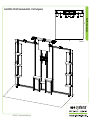
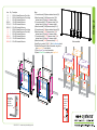
Step 1
Velcro: Back Edge
Velcro: Back Edge
Velcro: Back Edge
Velcro: Back Edge
Velcro: Back Edge
Velcro: Back Edge
Steps:
1) Install Baseplates [1] to bottom of verticals [2,7] using bolts.
2) Connect horizontals between verticals, as shown.
3) Apply fabric graphics to back of assembly, using Velcro.
Item
1
2
3
4
5
6
7
9/9A
10/10A
11/11A
12/12A
19/19A
Qty.
2
1
1
1
1
1
1
1/1
1/1
1/1
1/1
1/1
Description
Baseplate
85.75”h S44 Vertical Extrusion
86”h S44 Vertical Extrusion w/ MOD-300 Aero connector
86”h S44 Vertical Extrusion
86”h S44 Vertical Extrusion
86”h S44 Vertical Extrusion w/ MOD-300 Aero connector
85.75”h S44 Vertical Extrusion
22”w S44 Horizontal Extrusion
22”w S44 Horizontal Extrusion
22”w S44 Horizontal Extrusion
69.622”w S44 Horizontal Extrusion
69.622”w S44 Horizontal Extrusion
1
23
19 910 11
12
19A 9A 10A 11A 12A
67
5
4
1
When assembled
Attach graphics
to velcro on back of
assembled frame
Velcro: Back Top Edge
Velcro: Back Bottom Edge Velcro: Back Bottom Edge
Velcro: Back
Bottom Edge
Velcro: Back
Bottom Edge Velcro: Back
Bottom Edge
Velcro: Back Top Edge
Velcro: Back
Top Edge
Velcro: Back
Top Edge
Velcro: Back
Top Edge

866.463.2611 • www.ecosystemsdisplays.com
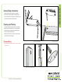
Step 2
Item
13
14
15
16/16A
17/17A
18/18A
Qty.
1
1
1
1
1/1
1/1
Description
24”h S44 Vertical Extrusion w/ Door Stop
24”h S44 Vertical Extrusion w/ Door Hinge
22”w Z45 Horizontal Extrusion
12”w Z45 Horizontal Extrusion
12”w Z45 Horizontal Extrusion
22”w Z45 Horizontal Extrusion
13
14
15
16/16A
17/17A
18/18A
1
1
1
1
1/1
1/1
24”h S44 Vertical Extrusion w/ Door Hinge
24”h S44 Vertical Extrusion w/ Door Stop
22”w Z45 Horizontal Extrusion
12”w Z45 Horizontal Extrusion
12”w Z45 Horizontal Extrusion
22”w Z45 Horizontal Extrusion
Steps:
1) Connect horizontal [15] between backwall verticals [3,4].
2) Attach horizontals [16,16A] between vertical [13] &
backwall vertical [3], sliding infill between verticals.
3) Connect horizontals [17,17A] between vertical [14] &
backwall vertical [4], sliding infill between verticals.
4) Attach horizontals [18,18A] between verticals [13,14].
5) Connect horizontal [15] between backwall verticals [5,6].
6) Attach horizontals [16,16A] between vertical [13] &
backwall vertical [5], sliding infill between verticals.
7) Connect horizontals [17,17A] between vertical [14] &
backwall vertical [6], sliding infill between verticals.
8) Attach horizontals [18,18A] between verticals [13,14].
9) Install Door to verticals [14] & [13]. See Door Attachment detail.
10) Attach Shelf Supports to inside of assemblies, using Velcro;
place Internal Shelf in each cabinet.
11) Place Counter Tops on top of assemblies.
12) Attach A5 Shelf Pins to verticals, place Bridge Shelf.
Door
Hinge
Hinge
Slide pin into
hinge attached
to vertical.
Slide door
hinge over pin.
Door Attachment
*
Pin
15
13
14
16A
17A
18A
18
16
17
D
o
or
*
*
i
n
f
i
l
l
i
n
f
i
l
l
15
3
4
5
6
13
14
16A
17A
18A
18
16
17
D
o
or
*
*
i
n
f
i
l
l
i
n
f
i
l
l
When assembled
Shelf Pin
Slide shelf pin
into groove of
extrusion &
tighten set
screw to
secure.
set
screw
*
***
*
Counter Top
Shelf Counter Top
Shelf
Bridge
Shelf

866.463.2611 • www.ecosystemsdisplays.com
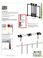
Step 3
Connections are made by holding the button
down and sliding the red tube into opposing
tube until the connection is made. To disassemble
push button and pull or twist extrusions apart.
Push-Button
Push-Button
66
6
6
Numbered Label
Using Your Setup Instructions
The Aero Overhead Sign Setup Instructions are created specically for your conguration. They include an
exploded view of the frame which is sequentially numbered. We encourage you to study the instructions
before attempting to assemble your exhibit.
Connections are kept very simple: no tools. Everything assembles with push-button
connectors and pre-connected horizontal sections.
Cleaning and Packing Your Display
1) Use care when cleaning aluminum extrusion or acrylic inserts. Use only non-abrasive cleaners.
2) Retain all packing material. It will make re-packing much easier and will reduce the likelihood
of shipping damage.
AC
D
B
Steps:
1) Assemble Aero frame in alphabetical order as shown.
2) Install Canopy Mounts to top of backwall verticals.
3) Connect assembled Aero frame to top of Canopy Mounts.
See Canopy Installation detail.
Canopy
Installation
*
Slide assembled
aero canopy supports
over installed
mount barrels.
Canopy
Mount
Aero Frame
Support Arm
When assembled
**

866.463.2611 • www.ecosystemsdisplays.com
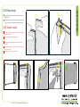
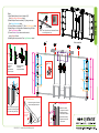
Step 4
When assembled
Steps:
1) Install Monitor Mount to front of verticals [4,5].
See Monitor Mount Attachment detail.
2) Attach Graphic Panels to verticals [2,7] using screw caps.
See Graphic Attachment detail.
3) Connect Shelves to verticals [2,7]. See Shelf Attachment detail.
4) Attach Wings to left & right sides of backwall using A10 clips.
See Wing Attachment detail.
5) Connect Header Graphic above monitor mount,
using H8 clips & Velcro.
6) Attach Lights to top horizontal. See Light Attachment detail.
Monitor Mount Attachment
Insert connector
into groove of
extrusion.
Tighten setscrew
to secure in place.
Attach wall plate to
connectors
using bolts provided.
Setscrew
Setscrew
*
Graphic
Screw
Cap
V20
Graphic Attachment
Slide V20 connector into groove
of extrusion, then secure graphic
to connector using screw cap.
*
Shelf Attachment
Insert lock into groove of vertical
extrusion and tighten setscrew.
Lock Setscrew
Back of Shelf
Setscrew will face
outward for ease
of assembly
*
2) Tighten set screw to
secure A10 to extrusion.
1) Slide A10 connector
into groove of extrusion.
Wing Attachment
*
Wing
4) Tighten knob to secure
wing in place.
3) Insert Infill into Clamp
1
2
3
4
*
Lock Clip into Groove of Horizontal Extrusion,
then slide Light onto Clip.
Clip
Light Extrusion
Light Attachment
Clip
Light
*
*
*
*
*
*
*
*
*
*
*
*
*
*
*
*
*
*
*
Shelf
Monitor
Mount
Light
Shelf
Shelf
**
**
*
w
in
g
w
in
g
w
in
g
H
eade
r
G
r
ap
h
i
c
w
in
g
Gra
p
h
ic
G
r
a
p
h
i
c
G
r
a
p
h
i
c
Light
Light Light
*
Shelf
Shelf
Shelf
Gra
p
h
i
c
G
r
a
p
h
i
c
G
r
a
p
h
i
c
*
*
*
*
*
*
*
*H8 Clip
Velcro
***
-
 1
1
-
 2
2
-
 3
3
-
 4
4
-
 5
5
-
 6
6
-
 7
7


Classic Exhibits ECO-2067 Setup Instructions
- Typ
- Setup Instructions
w innych językach
- English: Classic Exhibits ECO-2067
Powiązane artykuły
-
Classic Exhibits ECO-1050 Setup Instructions
-
-
-
-
-
-
-
-
-