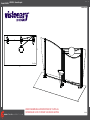
Classic Exhibits VK-2059 Setup Instructions
- Typ
- Setup Instructions

www.classicexhibits.com
Step 1
Page 1 of 3
866.652.2100
© 2008
WHEN DISASSEMBLING ALUMINUM EXTRUSION, TIGHTEN ALL
SETSCREWS AND LOCKS TO PREVENT LOSS DURING SHIPPING
Order #XXXXX - VK-2059 - General Layout
10’
20’
Plan View

www.classicexhibits.com
Step 2
Page 2 of 3
866.652.2100
© 2008
WHEN DISASSEMBLING ALUMINUM EXTRUSION, TIGHTEN ALL
SETSCREWS AND LOCKS TO PREVENT LOSS DURING SHIPPING
Order #XXXXX -
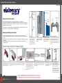
The Tool
Typical Connection Horizontal Inline Connection (remove only one setscrew)
Base Plate Connection Vertical Connection
(remove only two setscrews)
Most exhibits can be assembled
with the supplied Hex Key Tool.
Occasionally, a flat head screw-
driver may be required.
Most horizontal extrusion connections have a patented expandable lock.
This lock inserts into the groove of an opposing extrusion. Tightening the
lock with the Hex Key Tool expands the lock and creates a strong positive
connection.
Remove only (1) setscrew when disassembling.
Replace setscrew in extrusion after assembling it.
Before packing, replace setscrew in extrusion to
avoid losing it.
Attach base plate to round or
square vertical extrusion using
the bolt provided. Be careful not
to strip the threads.
When vertical extrusions are
packed in portable cases rather
than crates or tubs, they must be
broken down into smaller section
which then require assembly.
Remove only (2) setscrews when
disassembling. Replace setscrews
in extrusion after assembling it.
Before packing, replace setscrew
s
in extrusion to avoid losing them.
Using Your Setup Instructions
The Euro LT Hybrids Setup Instructions are created specifically for your configuration.
They are laid out sequentially in levels, including exploded views, and a logical series of detailed steps
to assemble the main structure and components. We encourage you to study the instructions before
attempting to assemble your exhibit.
Each page reminds you to tighten the setscrews after disassembling your exhibit to prevent loss of the
locks and setscrews (see below in RED). This is VERY IMPORTANT.
Cleaning and Packing Your Display
1) Use care when cleaning aluminum extrusion or acrylic inserts. Use only non-abrasive cleaners.
2) When cleaning laminate inserts, countertops, or panels use mild cleansers and a soft material such as
cotton.
3) Keep all display components away from extreme heat and long exposure to sunlight to avoid warping
and fading.
4) Retain all packing material. It will make re-packing much easier and will reduce the likelihood of
shipping damage.
Typical Connection (cont’d) Numbered Label
Each extrusion contains a numbered
label which corresponds with setup
instructions. The label is located within
a groove of the extrusion (when
possible). With extrusion components
the labels contain Black numbers unless
otherwise specified.
Detail C EliateDDliateDDetail B
Detail A
Setscrews
CutAwayViewOf
Slide Clips
L
e
f
t
P
a
n
e
l
R
i
g
h
t
P
a
n
e
l
Left Hand
Grasps Panel
Firmly
With Right Hand Thumb
Close to Seam
Squeeze,
Push Forward,
And Lift
Color Coded Clip
w/ assembly number
Panel Lock
When Required
Black Clip
is bottom of
panel
Connector Top View of Panels with LocksExample of Connection
Color Coded Clip
w/ assembly number
is top of panel
Panel Lock
When Required
Each component has 2 clips,
the lower clip is ALWAYS
black. The top clip is color
coded to distinguish which
level. The color coded clip
also contains the numbered
label.
Components connect together
by aligning them and sliding
downward connecting clips
together.
Configurations are assembled
from left to right, usually starting
with #1 and following the
numbered sequence.
The first level of components contain pan
e
locks that are located at the top of the
panel for extra stability and seamless con-
nection. When disassembling panels twist
top connection slightly and lift right panel
upward.
General Setup Instructions for Extrusion System
Level 1 = Blue
Level 2 = Red
Level 3 = Green
Level 4 = Black
General Setup Instructions

www.classicexhibits.com
Step 1
Page 1 of 3
866.652.2100
© 2008
WHEN DISASSEMBLING ALUMINUM EXTRUSION, TIGHTEN ALL
SETSCREWS AND LOCKS TO PREVENT LOSS DURING SHIPPING
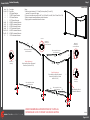
Order #XXXXX - Backwall Assembly
Item
1/1a/1b
2
3
4
5
6a/6b
7a/7b
8a/8b
9a/9b
10a/10b
11a/11b
12
Description
Base Plate
96”h Vertical Extrusion
79.7982”h Vertical Extrusion
96”h Vertical Extrusion
82.72”h Vertical Extrusion
48.0185“w Horizontal Extrusion
49.2385”w Horizontal Extrusion
43.087“w Horizontal Extrusion
43.01”w Horizontal Extrusion
44.4215”w Horizontal Extrusion
45.1683”w Horizontal Extrusion
8.551”w Horizontal Extrusion
Qty.
1/1/1
1
1
1
1
1/1
1/1
1/1
1/1
1/1
1/1
2
Steps:
1) Attach vertical extrusions [2, 3, 4 and 5] to base plates [1, 1a and 1b],
see detail D on general info. page.
2) Connect horizontal extrusions [6a to 6b, 7a to 7b, 8a to 8b, 9a to 9b, 10a to 10b and 11a to 11b].
3) Attach horizontal assemblies between vertical extrusions.
4) Apply graphics to assembled backwall as shown.
1a
4
5
6a
23
1
1b
6b
7a 7b
8b
8a
9b
9a
10b
10a
11b
11a
12
12
Connector
Plan View of
Vertical [5]
Plan View of
Vertical [4] w/
Connector Attached
12
10b
12
11b
10a
11a
7b
Connector
Plan View of
Vertical [3] w/
Connector Attached
6a
Plan View of
Vertical [2]
2
3
4
5
Attach Graphic to Back
of Horizontal Extrusions
Graphic Attachment
Velcro Graphic to Back of Horizontal
Extrusions [6a/6b and 7a/7b].
Graphic Attachment
Velcro Graphic to Back of Horizontal
Extrusions [8a/8b &10a/10b and
9a/9b & 11a/11b].
Velcro attached to upper
back of extrusions
Velcro attached to lower
back of extrusions
Velcro attached to upper
back of extrusions
Velcro attached to lower
back of extrusions

www.classicexhibits.com
Step 2
Page 2 of 3
866.652.2100
© 2008
WHEN DISASSEMBLING ALUMINUM EXTRUSION, TIGHTEN ALL
SETSCREWS AND LOCKS TO PREVENT LOSS DURING SHIPPING
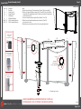
Order #XXXXX - Backwall Assembly (Cont’d)
Item
1c
13a
13b
14
15
16a/16b
17a/17b
Description
Base Plate
Support Leg Left
Support Leg Right
Shelf Support
96”h Vertical Extrusion
46.25”w Horizontal Extrusion
46.25”w Horizontal Extrusion
Qty.
1
1
1
1
1
1/1
1/1
Steps:
1) Attach vertical extrusion [15] and support legs [13a and 13b] to base plate [1c].
2) Attach shelf support [14] between support legs [13a and 13b], then set shelf atop
support with notched side fitting to vertical extrusion and secure with thumbscrews
to vertical extrusion [15].
3) Connect horizontal extrusions together [16a to 16b and 17a to 17b].
4) Attach horizontal assemblies between vertical extrusions [4 and 15],
placing insert as shown.
5) Attach wings to vertical extrusions [2 and 4], see wing attachment detail.
16b
17a 17b
15
16a
Slide A10 Clamp
into groove
of square extrusion.
When desired location
is found, tighten
set screw to secure.
Set-
Screw
A10
Tighten black plastic
set screw to secure
Wing in place.
Black Plastic
Set-screw
Wing Attachment
Plan View of
Vertical [15]
4
Plan View of
Vertical [4] w/
Connector Attached
12
10b 4
16b/17b
16a/17a
15
Connector
2
13a 13b
**
*
*
1c
Graphic Insert
14
*= Thumbscrew Location

www.classicexhibits.com
Step 3
Page 3 of 3
866.652.2100
© 2008
WHEN DISASSEMBLING ALUMINUM EXTRUSION, TIGHTEN ALL
SETSCREWS AND LOCKS TO PREVENT LOSS DURING SHIPPING
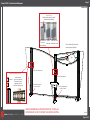
Order #XXXXX - Monitor Mount Attachment
Example of Monitor Mount Plate
Insert connectors
into groove of extrusion.
Then attach mount by
tightening screws on
frontside of monitor mount
Connector
Screw
MONITOR MOUNT
Attach monitor mount to vertical
extrusions after assembly.
Slide Mount into
Groove of
Vertical Extrusion.
Tighten
Setscrew Attach top Plate
and tighten screws
Hole for Wire Management
Hole for Wire Management
on Back of Extrusion
Sign
Velcro header sign to horizontal
extrusions where indicated.
Hole for Wire Management
Hole for Wire Management
on Back of Extrusion
-
 1
1
-
 2
2
-
 3
3
-
 4
4
-
 5
5


Classic Exhibits VK-2059 Setup Instructions
- Typ
- Setup Instructions
w innych językach
- English: Classic Exhibits VK-2059
Powiązane artykuły
-
Classic Exhibits VK-1048 Setup Instructions
-
-
-
-
-
-
-
-
-