Classic Exhibits VK-1965 Setup Instructions
- Typ
- Setup Instructions

© 2017
www.classicexhibits.com
Order #XXXXX
SETUP INSTRUCTIONS
If you would like to tell us about your experience with your setup instructions please email us at [email protected]
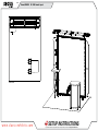
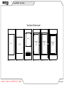
VK-1965 General Layout
Plan View
Scale: 18

© 2017
www.classicexhibits.com
Order #XXXXX
DO NOT USE POWER TOOLS
ALL CONNECTIONS MUST
BE TIGHTLY SECURED
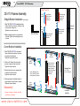
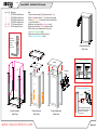
Part Identification - Numbering
Spline Connection Base Plate & Extrusion Connection
General Setup Instructions
- Read entire setup instruction manual prior to
unpacking parts and pieces.
- The setup instructions are created specifically
for this configuration.
- Setup instructions are laid out sequentially in
steps, including exploded views with detailed
explanation for assembly.
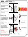
WARNING
Cleaning & Packing
- For Cleaning Metal, Plex, & Laminate Parts:
Use a MILD NON-ABRASIVE cleanser and
soft cloth/paper towel to clean all surfaces.
- Keep exhibit components away from heat
and prolonged sun exposure.
Heat and UV exposure will warp and
fade components.
- Retain all provided Packing Materials.
All provided packing materials are for
ease of repacking & component protection.
Disassembly
- For loss prevention, tighten all setscrews
and locks during disassembly
7A
Hex Tool - Essential for Assembly
Extrusion & Lock Connection Engaged Lock
LADDERS OR LIFTS
MAY BE REQUIRED
General Information

© 2017
www.classicexhibits.com
Order #XXXXX CEi-110 Assembly
CEI-110 Profile
Straight Connection
Corner Connection
TS RV 4
Bracket
Insert Bracket
into the Interior
Center Slot
of extrusion.
Slide connecting
extrusion over
exposed end
of bracket.
Secure extrusion
using remaining
set screws.
Set
Screw
CEI-110 Frames Assembly
Disassembly
1) Loosen set screws on brackets, then slide
extrusions off of brackets.
Straight Bracket Installation (when required)
1) Slide TWO-PIECE TS RV 4 straight bracket into
Interior Center Slot of extrusion so that two of the
set screws are inside groove.
Tighten two set screws to secure.
2) Slide connecting extrusion over exposed end
of bracket. Tighten two remaining set screws
to secure.
Corner Bracket Installation
1) Slide TWO-PIECE TS RV 2 L-bracket into
Interior Center Slot of extrusion so that two
set screws are inside groove.
Tighten two set screws to secure.
2) Slide one A1 L-Bracket into outer interior
grooves of upper and lower horizontals.
Tighten set screws to secure.
3) Slide vertical extrusion over exposed ends
of brackets in lower horizontal.
Tighten set screws to secure.
4) Slide exposed ends of installed brackets of
upper horizontal into open ends of verticals.
Tighten set screws to secure.
TS RV 2
Upper
Horizontal
Lower
Horizontal
Upper
Horizontal
Lower
Horizontal
TS RV 2
8 Brackets Total:
(4) - TS RV 4
(4) - A1 L-Brackets
A1
A1
Slide verticals over
brackets of lower
horizontal, then slide
upper horizontal &
brackets into grooves
& center slots
of verticals.
Completed
Assembly
Insert L-Brackets into the
Interior Center Slot & outer
interior grooves of extrusion.
Completed
Assembly
Secure inserted half
of bracket, using
set screws.

© 2017
www.classicexhibits.com Case 1 of 3
Order #XXXXX Case Packing
26A6 3 4 5 2A 3A 4A 5A
Base
Plates
(2x)
Wings
Counter Top
Shelf
10A
10/11
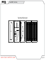
Top View of Each Level
Level 1 Level 3 Level 4 Level 5Level 2

© 2017
www.classicexhibits.com Case 2 of 3
Order #XXXXX Case Packing
Shelf
6
6
6A
6A
Assembled
Counter
Side
Assembled
Counter
Door
Counter
Infills
Top View of Each Level
Level 1 Level 2 Level 3 Level 4 Level 5 Level 6
Shelf Supports
Assembled
Counter
Side

© 2017
www.classicexhibits.com Case 3 of 3
Order #XXXXX Case Packing
Graphics
Literature Holders
& Monitor Mount
Setup Hardware
Level 1
Canopy Pieces
in Bag

© 2017
www.classicexhibits.com Step 1 of 4
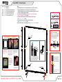
Order #XXXXX Backwall Assembly
Item
1
2/2A
3/3A
4/4A
5/5A
6/6A
Qty.
2
1/1
1/1
1/1
1/1
1/1
Description
Base Plate
46” CEI-110 Horizontal Extrusion
46” CEI-110 Horizontal Extrusion
46” CEI-110 Vertical Extrusion
46” CEI-110 Vertical Extrusion
46” S44 Vertical Extrusion
Steps:
1) Attach Base Plates [1] to lower Vertical Extrusions [2] and [3], using bolts.
2) Connect Horizontal Extrusions [2,2A] [3,3A] and Vertical Extrusions
[4,4A] [5,5A] together, then connect Extrusion assemblies together at corners.
See CEI-110 Assembly page for details.
3) Connect Lights and Transformers. See Light to Light Connection and
Light to Transformer Connection details.
4) Connect Vertical Extrusions [6] and [6A] together, using Connector.
See Extrusion Connector detail.
5) Connect [6/6A] assembly to [4/4A] assembly, using Bolts.
See S44 to CEI-110 Connection detail.
6) Install SEG Graphic to front of Backwall. See SEG Graphic Installation detail.
1
2
2A
3
4A
4
6A
6
5A
5
3A
1
Set Screws
Connector
Extrusion Connector
Slide upper Extrusion
over Connector and
rest on lower Extrusion.
Secure with Set Screws.
*
To prevent product loss, Keep
all screws attached to Connector,
after disassembling.
*
*
*
*
*
S44 to CEI-110 Connection
*
Set
Screw
Bolt
V4
CEI110
Top View
S44 Bolt
Slide V4 Connector into groove of S44
Extrusion, then secure with Set Screw.
Attach CEI-110 to S44, using bolt.
Graphic Removal
To remove the graphic from
the frame, locate the fabric
pull tab. Gently pull up on the
tab to remove the fabric.
Step 1
Insert corner A. Turn edge of
graphic so silicon welt is
perpendicular to face of
graphic. Insert narrow side
of welt with fabric to outside
into the channel. Repeat for
other side of this corner.
Step 2
Repeat Step 1 for opposite
corner C, then insert corner
B, followed by corner D, to
complete the installation of
the corners.
Step 3
Once all corners are inserted,
press one silicon edge into
channel from corners and
work toward the center.
Make sure welt is fully inserted
into channel. Continue until
all sides are done. Smooth
out edges of graphic.
SEG Graphic Installation
It is important to first insert
graphic into each alternate
corner then to the sides of
the frame. If this is not done,
graphic will not fit into the
frame correctly.
Corner A
Corner D
Corner B
Corner C
++
+
-
-
-
to power
Lights
Male
Male
Female
Female
Transformer
Light to Light Connection
Light to Tranformer Connection
Lighting Instalation Warning
Bolt Nylon
Washer
If utilizing your own hardware,
purchase Nylon Washers to prevent
metal screw heads from damaging
the circuit board. Attach no more
than seven lights per chain.
Diamond
Washer
Power
Break
Power
Break
Power
Break
Transformer
to power
Transformer
to power
Transformer
to power

© 2017
www.classicexhibits.com Step 2 of 4
Order #XXXXX Canopy Asssembly
Connections are made by holding the button
down and sliding the red tube into opposing
tube until the connection is made. To disassemble
push button and pull or twist extrusions apart.
Push-Button
Push-Button
66
6
6
Numbered Label
Using Your Setup Instructions
The Aero Overhead Sign Setup Instructions are created specically for your conguration. They include an
exploded view of the frame which is sequentially numbered. We encourage you to study the instructions
before attempting to assemble your exhibit.
Connections are kept very simple: no tools. Everything assembles with push-button
connectors and pre-connected horizontal sections.
Cleaning and Packing Your Display
1) Use care when cleaning aluminum extrusion or acrylic inserts. Use only non-abrasive cleaners.
2) Retain all packing material. It will make re-packing much easier and will reduce the likelihood
of shipping damage.
Steps:
1) Connect canopy pieces together as shown.
2) Apply pillow case graphic to assembled canopy.
AA
BB
DD
CC
Push-Button
Push button then rotate
for packing purposes

© 2017
www.classicexhibits.com Step 3 of 4
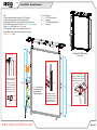
Order #XXXXX Backwall Attachments
Note: Curved Extrusion
[10] and Horizontal [11]
stay assembled for
shipping and packing.
10
10A
11
Item
10
10A
11
11A
Description
30.2” Z45 Curved Extrusion
Support Leg
12.184” Z45 Horizontal Extrusion
Flange Plate
Qty.
2
2
2
2
Steps:
1) Connect assembled Counter Top support [10,11] to Vertical [4].
3) Connect Support Leg [10A] to Counter Top support [10,11].
4) Attach Flange Plates [11A] to top of Curved Extrusions [10], using screw.
5) Attach Counter Tops to supports [11/11A]. See Counter Top Attachment detail.
6) Attach Wings to A10 Clamps. See A10 Clamp detail.
7) Attach assembled Canopy to top of Horizontal assembly [3/3A].
8) Attach Monitor Mount to Vertical Extrusion [4A], using Connectors.
See Monitor Mount detail.
Completed VK-1965 Assembly
(Front View)
Counter Top Attachment
*
Insert Screws, located on underside
of Counter Top, into holes on Flange
Plate then secure with Wing Nuts.
Wing Nut
Fixed
Screws
Flange
Plate
10
11
Counter Top
Bolt
*
11A
4A
4
5A
5
Canopy
Monitor Mount
Connectors
*
Slide Connectors into groove
of Extrusion. Tighten set screws
to secure Connectors in place.
Attach Monitor Mount back
plate to Extrusion, using Bolts.
Bolts
Monitor
Mount
Shelf
Knob
Set Screw
Connector
1) Slide Connector of Clamp
into extrusion groove.
2) Tighten set screw when
A10 is in desired location.
3) Insert Wing into Clamp.
4) Tighten knob on Clamp
to secure Wing in place.
A10 Clamp
A10 Clamp

© 2017
www.classicexhibits.com Step 4 of 4
Order #XXXXX Modied MOD-1551 Assembly
Infill
Infill
Infill
1
5
Velcro 6
5
Door
Shelf
Counter
Literature
Holder
6
2
3
5A 6A
5A
6A
4
3
4
Completed Assembly
(Front View)
Item
1
2
3
4
5/5A
6/6A
Qty.
1
1
1
1
2/2
1/1
Description
38” RSG520 Vertical Extrusion
38” RSG520 Vertical Extrusion
38” RSG520 Vertical Extrusion
38” RSG520 Vertical Extrusion
17” Z45 Horizontal Extrusion
22” Z45 Horizontal Extrusion
Steps:
1) Connect lower horizotnals [5] & [6] between verticals [1,2,3,4].
2) Place Infills between verticals [1,2,3,4], with Velcro facing inward.
3) Connect Shelf Supports to Velcro inside of Infills, then place Shelf
on top of Shelf Supports.
4) Attach door using hinges. See Door Connection detail.
5) Attach upper horizontals [5A, 6A & 7A] between verticals.
6) Place Counter on top of assembly, then lock in place.
See Counter Top Attachment detail.
7) Attach Literarure Holders to Verticals [3] and [4].
See Literature Holder Attachment detail.
Counter Attachments
(Back View)
Counter Assembly
(Back View)
Counter Assembly
(Back View)
Align hole with pin Rotate pin. Spring
will push pin into hole.
Counter Top Attachment
12
*
***
*
Shelf Support
Shelf Support
Shelf Support
Shelf Support
Door
Hinge
Hinge
Pin
Slide Pin into
Hinge attached
to Vertical.
Slide Door
Hinge over Pin.
Door Connection
*
*
*
Connector
Literature Holder Attachment
Locks
Literature
Holder
Attach angled end of Connector to
Literature Holder. Attach flat end of
Connector to Post. Tighten
locks to secure.
*
-
 1
1
-
 2
2
-
 3
3
-
 4
4
-
 5
5
-
 6
6
-
 7
7
-
 8
8
-
 9
9
-
 10
10


Classic Exhibits VK-1965 Setup Instructions
- Typ
- Setup Instructions
w innych językach
- English: Classic Exhibits VK-1965
Powiązane artykuły
-
Classic Exhibits TF-511 Setup Instructions
-
-
-
-
-
-
-
-
-