Classic Exhibits ECO-1067 Setup Instructions
- Typ
- Setup Instructions

Locked layer contains
placeholder marks.
866.463.2611 • www.ecosystemsdisplays.com
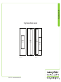
Setups
Locked layer contains
placeholder marks.
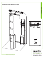
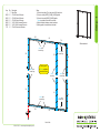
Plan View
10’
10’
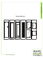
Order #XXXXX ECO-1067 10’x10’ Booth with ECO-33C Pedestal

Locked layer contains
placeholder marks.
866.463.2611 • www.ecosystemsdisplays.com
Locked layer contains
placeholder marks.
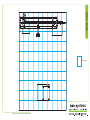
= 1 sq foot
Grid View

Locked layer contains
placeholder marks.
866.463.2611 • www.ecosystemsdisplays.com
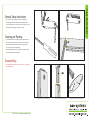
General Info
A7
General Setup Instructions
•The setup instructions are created specifically for your configuration.
•Setup instructions are laid out sequentially in levels, including exploded
views and a logical series of steps for assembly. We encourage you to study
the instructions before attempting to assemble your exhibit.
Hex Tool & Phillips Screwdriver are included for Assembling Exhibit Extrusion Lock Connectors
Numbering Instructions for Setups/Packing Inline Connection between Extrusions Baseplate Connection for Vertical Extrusions
Cleaning and Packing
•Use non-abrasive cleaners when cleaning extrusions or ECO Glass inserts.
•Use mild cleaners and soft materials such as cotton to clean all laminates.
•Keep exhibit components away form extreme heat and long exposure to
sun light. This will prevent warping and fading.
•Retain all packing material for ease of re-packing. This protects the exhibit
components and keeps each part organized.
Disassembling
•When disassembling exhibit, tighten all setscrews to prevent loss of hardware
in the shipping process.

Locked layer contains
placeholder marks.
866.463.2611 • www.ecosystemsdisplays.com
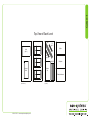
Case 1
Locked layer contains
placeholder marks.
Graphics
Lights
Setup Hardware
Top View of Each Level
Level 1
(Bottom level) (Top level)
Level 2 Level 3
Internal
Shelf
Infills
(Qty. 2)
Counter
Top
8,8A
10A
(Qty. 2)
10
(Qty. 2)
Shelf
Shelf
Shelf
9,9A,9B

Locked layer contains
placeholder marks.
866.463.2611 • www.ecosystemsdisplays.com
Case 2
Locked layer contains
placeholder marks.
Top View of Each Level
Level 1
(Bottom level) (Top level)
Level 2 Level 3
Base
Plate
Cabinet
Door
5A,6A 6B,5B
7A
7
4B 3A,2A 4A3B,2B

Locked layer contains
placeholder marks.
866.463.2611 • www.ecosystemsdisplays.com
Case 3
Locked layer contains
placeholder marks.
Top View of Each Level
Level 1
(Bottom level) (Top level)
Level 2 Level 3
Monitor
Mount
Header
Graphic
Aero
Frame
Wings
(Qty. 2)

Locked layer contains
placeholder marks.
866.463.2611 • www.ecosystemsdisplays.com
Case 4
Locked layer contains
placeholder marks.
Top View of Each Level
Level 1
93,7 1,5 2,4,6,8
Shelf
Counter
Top
Plex
Counter
Graphic
Level 2 Level 3 Level 4 Level 5 Level 6

Locked layer contains
placeholder marks.
866.463.2611 • www.ecosystemsdisplays.com
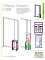
Step 1
Locked layer contains
placeholder marks.
FRONT VIEW
2B
2A
3A 4A
3B 4B
6A
6B
5A
5B
7A
7
1
When assembled
Item
1
2A,2B
3A,3B
4A,4B
5A,5B
6A,6B
7/7A
Qty.
3
1/1
1/1
1/1
1/1
1/1
1/1
Description
Base Plate
43”h S44 Vertical Extrusion
43”h S44 Vertical Extrusion
43”h S44 Vertical Extrusion
34.811”w S44 Horizontal Extrusion
34.811”w S44 Horizontal Extrusion
22”w S44 Horizontal Extrusion
Steps:
1) Connect base plates [1] to lower vertical [4A] using bolts.
2) Connect verticals [2A-2B], [3A-3B], [4A-4B] together.
3) Connect horizontals [5A-5B], [6A-6B] together.
Velcro is applied to back side of extrusions.
4) Attach horizontals between verticals as shown.
5) Attach graphic to backwall where indicated.
Attach graphic
to Velcro on back of
assembled frame
Velcro: Back
Outside Edge
Velcro: Back
Outside Edge
Velcro: Back
Outside Edge Velcro: Back
Outside Edge
Velcro: Back
Outside Edge
Velcro: Back
Outside Edge
Velcro:
Back Edge

Locked layer contains
placeholder marks.
866.463.2611 • www.ecosystemsdisplays.com
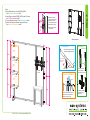
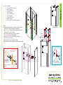
Step 2
Locked layer contains
placeholder marks.
Infill
Infill
When assembled
8
10A
9A
9B
3A/3B 4A/4B
10A
9
8A
10
Door
Shelf
Counter Top
10
Item
8
8A
9/9A
9B
10/10A
Qty.
1
1
1/1
1
2/2
Description
24.25”h S44 Vertical Extrusion w/ Door Stopper
24.25”h S44 Vertical Extrusion w/ Door Hinges
22”w Z45 Horizontal Extrusion
22”w Z45 Horizontal Extrusion
12”w Z45 Horizontal Extrusion
Steps:
1) Connect horizontals [9] & [9A] between verticals [8] & [8A].
2) Connect lower horizontals [10] between verticals.
3) Insert infills between verticals & secure with horizontals [10A].
4) Attach horizontal [9B] between backwall verticals [3A/3B] & [4A/4B].
5) Install Door between verticals [8,8A]. See Door Attachment detial.
6) Affix Shelf Supports to inside of assembly using Velcro; place internal Shelf.
7) Attach Counter Top to upper horizontals [9A/9B/10A].
See Counter Top Attachment detail.
12
Counter Top Attachment
*
Align hole with pin. Rotate pin. Spring
will push pin into hole.
Door
Hinge
Hinge
Slide pin into
hinge attached
to vertical.
Slide door
hinge over pin.
Door Attachment
*
Pin
Shelf support
Shelf support
Shelf support
Shelf support
*
**

Locked layer contains
placeholder marks.
866.463.2611 • www.ecosystemsdisplays.com
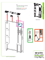
Step 3
Locked layer contains
placeholder marks.
Monitor
Mount
Wing
Wing
Wing
Wing
Monitor Mount
Attachment
Slide connectors into
groove of extrusion;
tighten setscrew to secure.
Then attach wall plate
to connectors using
supplied bolts.
Setscrew
*
*
Graphic
Cap
V20
Slide V20 connector into groove of
extrusion, then secure graphic to
connector using screw cap.
Graphic to Post Attachment
2) Tighten set screw to
secure A10 to extrusion.
1) Slide A10 connector
into groove of extrusion.
A10 Clamp Attachment
*
Wing
4) Tighten knob to secure
wing in place.
3) Insert Infill into Clamp
1
2
3
4
Shelf Attachment
Insert lock into groove of vertical
extrusion and tighten setscrew.
Lock Setscrew
Back of Shelf
Setscrew will face
outward for ease
of assembly
*
Steps:
3) Install Monitor Mount to verticals [3A/3B], [4A/4B].
See Monitor Mount Attachment detail.
4) Attach Wings to verticals [2A/2B], [4A/4B], using A10 clamps.
See A10 Clamp Attachment detail.
5) Connect Shelves to backwall. See Shelf Attachment detail.
5) Attach Front Graphics to backwall using standoff caps.
See Graphic to Post Attachment detail.
When assembled
Shelf
Graphic
Graphic
Graphic
*
*
Shelf
*
*
Shelf
*
*
**
*
*
*
*
**
*
*

Locked layer contains
placeholder marks.
866.463.2611 • www.ecosystemsdisplays.com
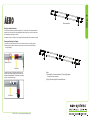
Step 4
Using Your Setup Instructions
The Aero Setup Instructions are created specifically for your configuration. The instructions include an
exploded view of the frame which is sequentially labeled. We encourage you to review the instructions
before attempting to assemble your exhibit.
Connections are kept very simple; no tools required. Everything assembles with push-button connectors.
Cleaning and Packing Your Display
1) Use care when cleaning aluminum extrusion or acrylic inserts. Use only non-abrasive cleaners.
2) Retain all packing material. It will make re-packing much easier and will reduce the likelihood
of shipping damage.
Push-Button
Push-Button
66
6
6
Numbered Label
Connections are made by holding the button down and
sliding the red tube into opposing tube until button locks
into the hole of the opposing tube. To disassemble, push button
and pull or twist extrusions apart.
Locked layer contains
placeholder marks.
7
8
5
6
3
4
1
2
When assembled
Steps:
1) Assemble Aero Frame parts labeled [1] through [8] together
in numerical order, as shown.
2) Apply Pillowcase Graphic to assembled frame.

Locked layer contains
placeholder marks.
866.463.2611 • www.ecosystemsdisplays.com
Step 5
Locked layer contains
placeholder marks.
Completed Assembly
Steps:
1) Use Canopy Mounts to attach canopy to upper verticals.
See Canopy Mount Attachment detail.
2) Attach light as shown. See Light Attachment detail.
3) Attach Header Graphic to backwall, using Velcro.
Canopy
Mount
Insert Canopy Mount into
threaded hole in top of vertical.
Turn barrel clockwise to
tighten in place.
Canopy Mount
Attachment
Turn to
tighten
*
*
*
*
*
Lock Clip into Groove of
Horizontal Extrusion, then
slide Light onto Clip.
Light Attachment
Slide light into light
receiving hardware
Lock into
groove of
horizontal
Header Gr
ap
hic
Velcro: Inside
Edges

Locked layer contains
placeholder marks.
866.463.2611 • www.ecosystemsdisplays.com
Step 6
Locked layer contains
placeholder marks.
When assembled
Plex Counter
Counter
1
2
3
4
5
6
Shelf
7
8
9
Graphic
Graphic
Cap
Attach Graphic to kiosk
using cap with treaded stud.
Graphic Attachment
Threaded Hole
in Front Panel
*
Interior of kiosk
body
Cap
Standoff
Barrel
Attach standoff barrels
to threaded holes in
Counter Support Leg.
Connect support leg to kiosk
using cap.
Counter Support Leg
Attachment
Counter
Support Leg
Insert cap on the
interior side of kiosk.
**
**
*
Shelf Supports
Shelf Supports
Shelf Supports
Shelf Supports
Steps:
1) Assemble panels & connectors [1] through [8] in numerical order.
Refer to the ECO Panel Install general information page.
2) Affix Shelf Supports to interior of assembled pedestal, using Velcro;
place interior Shelf on top of supports.
3) Attach Counter Support Leg [9] to Panel [3] of pedestal.
See Counter Support Leg Attachment detail.
3) Connect Standoff Graphic to front of Panel [5] of pedestal.
See Graphic Attachment detail.
4) Place Counter Top on top of assembled pedestal.
5) Attach Plex Counter to top of pedestal using stand-off Barrels & Caps.
Item
1
2
3
4
5
6
7
8
9
Qty.
1
1
1
1
1
1
1
1
1
Description
20”w x 40”h ECO Panel w/ Door
40”h 90° Connector
16”w x 40”h ECO Panel
40”h 90° Connector
20”w x 40”h ECO Panel
40”h 90° Connector
16”w x 40”h ECO Panel
40”h 90° Connector
19.5”w x 40.75”h x 2”d Counter Support Leg
-
 1
1
-
 2
2
-
 3
3
-
 4
4
-
 5
5
-
 6
6
-
 7
7
-
 8
8
-
 9
9
-
 10
10
-
 11
11
-
 12
12
-
 13
13


Classic Exhibits ECO-1067 Setup Instructions
- Typ
- Setup Instructions
w innych językach
- English: Classic Exhibits ECO-1067
Powiązane artykuły
-
Classic Exhibits ECO-2067 Setup Instructions
-
-
-
-
-
-
-
-
-
