
© 2022
Order #XXXXX
Locked layer contains
placeholder marks.
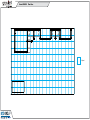
Plan View
10’
20’
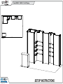
GK-2023 - 10’ x 20’ Display
If you would like to tell us about your experience with your setup instructions please email us at [email protected]
SETUP INSTRUCTIONS

© 2022
Order #XXXXX
Locked layer contains
placeholder marks.
= 1 sq foot
Plan View

© 2022
Order #XXXXX
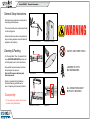
DO NOT USE POWER TOOLS
ALL CONNECTIONS MUST
BE TIGHTLY SECURED
Part Identification - Numbering
Spline Connection Base Plate & Extrusion Connection
General Setup Instructions
- Read entire setup instruction manual prior to
unpacking parts and pieces.
- The setup instructions are created specifically
for this configuration.
- Setup instructions are laid out sequentially in
steps, including exploded views with detailed
explanation for assembly.
WARNING
Cleaning & Packing
- For Cleaning Metal, Plex, & Laminate Parts:
Use a MILD NON-ABRASIVE cleanser and
soft cloth/paper towel to clean all surfaces.
- Keep exhibit components away from heat
and prolonged sun exposure.
Heat and UV exposure will warp and
fade components.
- Retain all provided Packing Materials.
All provided packing materials are for
ease of repacking & component protection.
Disassembly
- For loss prevention, tighten all set screws
and locks during disassembly.
7A
Hex Tool - Essential for Assembly
Extrusion & Lock Connection Engaged Lock
LADDERS OR LIFTS
MAY BE REQUIRED
General Information

© 2022
Order #XXXXX
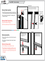
Assembly Assembly Cont’d
Stacking Unstacking
Stacking Assembly
1) Place one horizontal frame on top of the other, lining up the
center grooves.
2) Turn stacking lock clockwise to tighten into place. Repeat
for each lock.
Stacking Disassembly
1) Turn the stacking lock counter-clockwise to loosen.
2) The whole spring on the stacking lock should be in view to
release each frame. The disengaged spring should release
the stacking lock. If not, keep turning the stacking lock until
it disengages.
Side-by-Side Assembly
1) Frames: Place frames side-by-side with one higher than the
other, then slide panel down to lock panels securely together.
2) Corner Connectors: Repeat Step 1 for installing corner
connectors to frames.
Side-by-Side Disassembly
1) Pull pin lock outwards to disengage.
2) Pull frames upward and apart at the same time to detatch.
Push stacking lock into the slot
of the upper frame, then spin the
cap to tighten the lock.
Push pin lock into hole of connecting frame.
Note: Block of pin lock will secure in groove.
Disengage the stacking lock by
spinning the cap counter
clockwise and pulling down.
Cap
Stacking
Lock
Pin Lock
Top View
Corner Connector
SEG
Grooves
Note: Orientation of Corner
Connector may change.
Gravitee Assembly

© 2022
Crate 1 of 1
Order #XXXXX
Locked layer contains
placeholder marks.
CRATE PACKING
Crate Packing

© 2022
Step 1 of 6
Order #XXXXX
Locked layer contains
placeholder marks.
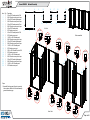
When assembled
Steps:
1) Assemble Gravitee panels & posts in numerical
order as shown. Refer to the Gravitee Assembly
general information page.
TOP VIEW
FRONT VIEW
Item
1
2
3
4
5
6
7
8
9
10
11
12
13
14
15
16
17
18
19
20
21
22
23
24
Qty.
1
1
1
1
1
1
1
1
1
1
1
1
1
1
1
1
1
1
1
1
1
1
1
1
Description
38”w x 95”h Gravitee panel w/ S44
94.5”h Gravitee corner post w/ caps
46”w x 95”h Gravitee lightbox panel
94.5”h Gravitee corner post w/ caps
38”w x 95”h Gravitee panel w/ Door
94.5”h Gravitee corner post w/ caps
46”w x 95”h Gravitee panel
95”h Gravitee corner post
46”w x 95”h Gravitee panel w/ S44
95”h Gravitee corner post
14.125”w x 95”h Gravitee panel
94.5”h Gravitee corner post w/ caps
38”w x 95”h Gravitee lightbox panel
94.5”h Gravitee corner post w/ caps
14.125”w x 95”h Gravitee panel
95”h Gravitee corner post
32.5”w x 95”h Gravitee Panel w/ S44
95”h Gravitee corner post
14.125”w x 95”h Gravitee panel
94.5”h Gravitee corner post w/ caps
38”w x 95”h Gravitee lightbox panel
94.5”h Gravitee corner post w/ caps
14.125”w x 95”h Gravitee panel
95”h Gravitee corner post
1
2
3
4
5
6
7
8
9
10
11
12
13
14
15
16
17
18
20
21
22
23
24
19
1
234
5
6 7 8 9 10
11
12 13 14
15
16 17 18
20 21 22
23
24
19
D
o
or
Top View
Top View
Top View
Top View
Top View
Top View
Top View
Top View
Top View
Top View
Top View
Top View
Backwall Assembly

© 2022
Step 2 of 6
Order #XXXXX
Locked layer contains
placeholder marks.
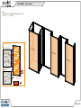
Transformers
Power Break
Maximum 8 light strips
per transformer.
Light Connection
to transformer
Light Connector
Cord
Connect lights
together as shown.
Light to Light Attachment
Light to Transformer
Attachment
Transformer
144W / 6 Amp / 24V
Steps:
1) Connect power cords to LED lights in panels [3], [13] & [21].
See Light Connection detail.
Li
g
ht Pane
l
Li
g
ht Pane
l
Li
g
ht Pane
l
3
13
21
Light Connection

© 2022
Step 3 of 6
Order #XXXXX
Locked layer contains
placeholder marks.
wrap
corner
wrap
corner
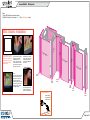
SEG Graphic Installation
Corner A
Corner D
Corner B
Corner C
It is important to first insert
graphic into each alternate
corner, then to the sides of
the frame. If this is not done,
graphic will not fit into the
frame correctly.
Step 1
Insert corner A. Turn edge of
graphic so silicon welt is
perpendicular to face of
graphic. Insert narrow side
of welt with fabric to outside
into the channel. Repeat for
other side of this corner.
Step 2
Repeat Step 1 for opposite
corner C, then insert corner
B, followed by corner D, to
complete the installation of
the corners.
Graphic Removal
To remove the graphic from
the frame, locate the fabric
pull tab. Gently pull up on
the tab to remove the fabric.
Step 3
Once all corners are inserted,
press one silicon edge into
channel from corners and
work toward the center.
Make sure welt is fully inserted
into channel. Continue until
all sides are done. Smooth
out edges of graphic.
S
E
G
G
r
a
p
hic
S
E
G
G
r
a
p
hic
SEG Gr
ap
hic
SEG Gr
ap
hic SEG Gr
ap
hic
G
r
a
ph
i
c
SE
G
G
r
a
ph
i
c
SE
G
G
raphi
c
SE
G
G
raphi
c
SE
G
G
raphi
c
SE
G
wrap
corner
wrap
corner
wrap
corner
wrap
corner
S
E
G
G
r
a
p
hic
Steps:
1) Apply SEG Graphics to panels as shown.
2) Attach Perf Light to top of panels [1,9,17]. See Light Attachment detail.
17
9
1
Light Attachment
Attach lights to
top of panel and
tighten in place.
*
**
*
SEG Graphics

© 2022
Step 4 of 6
Order #XXXXX
Locked layer contains
placeholder marks.
47.75”w Shelves
32.25”w Shelves
29.875”w Shelves
SIDE VIEW
Item
--
--
--
Qty.
4
4
4
Description
29.875”w x 10”d Shelf w/ Z31
32.25”w x 10”d Shelf w/ Z31
45.75”w x 10”d Shelf w/ Z31
Steps:
1) Attach Shelves to vertical extrusions in panels [9], [17] & [1] as shown.
See Shelf Attachment detail.
When assembled
9
17
1
*
*
*
*
*
*
*
*
*
*
*
*
*
*
*
***
**
**
**
Shelf Attachment
Lock Setscrew
Setscrews will face
outward for ease
of assembly
*Insert locks into groove
of vertical extrusion &
tighten setscrews.
Back of Shelf
Shelf Attachment

© 2022
Step 5 of 6
Order #XXXXX
Locked layer contains
placeholder marks.
25
26
27
28
29
30
31
32
1
2
3
Door
Door
Back View
*
*
*
*
Back View
Door
Hinge
Hinge
Slide pin into
hinge attached
to vertical.
Slide door
hinge over pin.
Door Connection
*
Pin
Top View
Top View
Top View
door
hinge
Top View
door
hinge
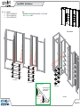
Steps:
1) Assemble Gravitee panels and posts in numerical order, as shown,
making sure Velcro is facing inward. See Gravitee Panel Assembly
sheet, for instruction.
2) Attach horizontal extrusions [1] and [2] between posts [25] and [32].
3) Attach vertical [3] between horizontals [1] and [2].
4) Connect doors to posts [25] and [32]. See Door Connection detail.
Item
25
26
27
28
29
30
31
32
1,2
3
Qty.
1
1
1
1
1
1
1
1
1,1
1
Description
38”h Gravitee Corner Post w/ Door Attachment
14.125”w x 38”h Gravitee Panel Frame
38”h Gravitee Corner Post
19”w x 38”h Gravitee Panel Frame
19”w x 38”h Gravitee Panel Frame
38”h Gravitee Corner Post
14.125”w x 38”h Gravitee Panel Frame
38”h Gravitee Corner Post w/ Door Attachment
37.0945”w Z45 Horizontal Extrusion
34.4173”h Z45 Vertical Extrusion
GJOD-1558 Counter Assembly

© 2022
Step 6 of 6
Order #XXXXX
Locked layer contains
placeholder marks.
*
Shelf Supports
Shelf
Supports
Completed Assembly
Shelf
31
25
32
1
3
Counter Top
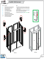
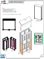
Steps:
1) Wrap SEG Graphic around front and sides of assembled counter.
See SEG Graphic Installation sheet for instruction.
2) Connect shelf supports to Velcro, then place shelf on top of supports.
3) Lock counter top to panels [26] and [31]. See Counter Top Lock detail.
Back View Front View
*
Top View
Align hole with pin Rotate pin. Spring
will push pin into hole.
Counter Top Lock
12
*
Pin
Hole
26
2
Keep connectors [25] [32] extrusions [1] [2] [3] and doors assembled, when packing.
GJOD-1558 Counter Assembly (cont’d)
-
 1
1
-
 2
2
-
 3
3
-
 4
4
-
 5
5
-
 6
6
-
 7
7
-
 8
8
-
 9
9
-
 10
10
-
 11
11


w innych językach
Powiązane artykuły
Inne dokumenty
-
Classic Exhibits GK-1008 Setup Instructions
-
-
-
-
-
-
-
-
-