Classic Exhibits ECO-1050 Setup Instructions
- Typ
- Setup Instructions

Locked layer contains
placeholder marks.
866.463.2611 • www.ecosystemsdisplays.com
Setups
Locked layer contains
placeholder marks.
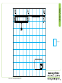
Plan View
10’
10’
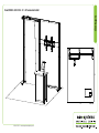
Order #XXXXX - ECO-1050 - 10’ x 10’ Sustainable Exhibit

Locked layer contains
placeholder marks.
866.463.2611 • www.ecosystemsdisplays.com
Locked layer contains
placeholder marks.
= 1 sq foot
Grid View

Locked layer contains
placeholder marks.
866.463.2611 • www.ecosystemsdisplays.com
A7
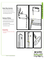
General Setup Instructions
•The setup instructions are created specifically for your configuration.
•Setup instructions are laid out sequentially in levels, including exploded
views and a logical series of steps for assembly. We encourage you to study
the instructions before attempting to assemble your exhibit.
Hex Tool for Assembling Exhibit Extrusion Lock Connectors
Numbering Instructions for Setups/Packing Inline Connection between Extrusions Baseplate Connection for Vertical Extrusions
Cleaning and Packing
•Use non-abrasive cleaners when cleaning extrusions or ECO Glass inserts.
•Use mild cleaners and soft materials such as cotton to clean all laminates.
•Keep exhibit components away form extreme heat and long exposure to
sun light. This will prevent warping and fading.
•Retain all packing material for ease of re-packing. This protects the exhibit
components and keeps each part organized.
Disassembling
•When disassembling exhibit, tighten all setscrews to prevent loss of hardware
in the shipping process.
General Info

Locked layer contains
placeholder marks.
866.463.2611 • www.ecosystemsdisplays.com
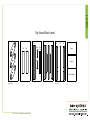
Case 1
Locked layer contains
placeholder marks.
2A
23 4
5 5A
10A
9A
10B
9B
8A 8B
6,6A
7,7A
4A3A
Graphics
Lights
Setup Hardware
Top View of Each Level
Level 1
(Bottom level) (Top level)
Level 2 Level 3 Level 4 Level 5

Locked layer contains
placeholder marks.
866.463.2611 • www.ecosystemsdisplays.com
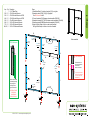
Step 1
Locked layer contains
placeholder marks.
1
2
2A
3A
4A
5A
6A
8A 8B
7A
5
67
3
4
1
1
When assembled
Item
1
2/2A
3/3A
4/4A
5/5A
6/6A
7/7A
8A,8B
Qty.
1
1/1
1/1
1/1
1/1
1/1
1/1
1,1
Description
8” x 22” Base Plate
45”h S44 Vertical Extrusion
45”h S44 Vertical Extrusion w/ PR63
45”h S44 Vertical Extrusion w/ PR63
45”w S44 Horizontal Extrusion
28.5”w Z45 Horizontal Extrusion
28.5”w Z45 Horizontal Extrusion
28.5”w Z140 Horizontal Extrusion
Steps:
1) Attach Base Plates [1] to bottom of verticals [2,3,4], using bolts.
2) Assemble verticals [2-2A], [3-3A], [4-4A] together.
See S44 Connection detail.
3) Connect horizontals [5,5A] between vertical assemblies [2/2A,3/3A].
4) Assemble horizontals [6-7], [6A-7A] between vertical assemblies [3/3A,4/4A].
5) Attach horizontals [8A-8B] between vertical assemblies [3/3A,4/4A].
6) Apply left Fabric Graphic to Velcro on back side of backwall;
affix right Fabric Graphic to Velcro on front side of backwall.
***
Screws
Connector
S44 Connection
Slide extrusion over
connector and rest on
lower vertical;
secure with screws.
**To prevent product loss,
Keep all screws attached
to connector piece after
disassembling
*
pinch
PR63 Attachment
Attach conduit where
indicated by pinching
the opening and
inserting into the
groove of extrusion.
KEEP PR63 ATTACHED
TO EXTRUSIONS.
DO NOT REMOVE
DURING TEAR DOWN.
PR63 conduit
Velcro: Back
Inside Edge
Velcro: Back
Inside Edge
Velcro: Front
Top Edge
Velcro: Front
Bottom Edge
Velcro: Back
Inside & Outside
Edge
Velcro: Front
of PR63
Velcro: Front
of PR63
Velcro: Front
of PR63
Velcro: Front
of PR63
Velcro: Back
Inside Edge
Velcro: Back
Inside Edge Velcro: Back
Inside Edge

Locked layer contains
placeholder marks.
866.463.2611 • www.ecosystemsdisplays.com
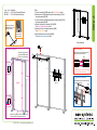
Step 2
Locked layer contains
placeholder marks.
Front Graphic Attachment
Wrap top of graphic around
horizontal [9A/9B] & attach
to Velcro on top front edge.
SIDE VIEW
SIDE VIEW
Graphic Graphic
Velcro
Velcro
Wrap bottom of graphic under horizontal [5] & affix
to Velcro on back outside edge of extrusion.
When assembled
9A 9B
2/2A
3/3A
8A/8B
10A
10B
Monitor
Mount
Light
Item
9A/9B
10A/10B
Qty.
1/1
1/1
Description
24.311”w S44 Horizontal Extrusion
9.75”w Z44 Horizontal Extrusion
Steps:
1) Connect horizontals [9A-9B] together. See S44 Connection detail.
2) Attach horizontal [10A] between backwall vertical assembly [2/2A] &
horizontal assembly [9A/9B].
3) Connect horizontal [10B] between backwall vertical assembly [3/3A] &
horizontal assembly [9A/9B].
4) Attach Front Graphic to horizontals [5] & [9A/9B].
See Front Graphic Attachment detail.
5) Attach Light to top of horizontal assembly [9A/9B].
See Light Attachment detail.
6) Install Monitor Mount to horizontals [8A/8B].
See Monitor Mount Attachment detail.
S44 Connection
Slide extrusion over connector and rest on
lower vertical; secure with screws.
**To prevent product loss, keep all screws attached
to connector piece after disassembling
Screws
Connector
*
**
*
Monitor Mount
Bolts
Monitor Mount Attachment
*
Install Monitor Mount to horizontal extrusion
using bolts & wing nuts. Wing
nuts
Z
14
0
*
Lock Clip into Groove of
Horizontal Extrusion, then
slide Light onto Clip.
Light Attachment
Slide light into light
receiving hardware
Lock into
groove of
horizontal
G
r
a
p
h
i
c
-
 1
1
-
 2
2
-
 3
3
-
 4
4
-
 5
5
-
 6
6


Classic Exhibits ECO-1050 Setup Instructions
- Typ
- Setup Instructions
w innych językach
- English: Classic Exhibits ECO-1050
Powiązane artykuły
-
Classic Exhibits ECO-2067 Setup Instructions
-
-
-
-
-
-
-
-
-