
GB
PL
Operating Instructions
Instrukcja obsługi
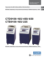
Temperature Dry Well Calibrators/Micro Calibration Baths
Kalibrator temperatury z suchym otworem pomiarowym / Kalibrator kąpielowy - mikro
CTD9100-165/-450/-650
CTB9100-165/-225
Kalibrator temperatury z suchym otworem pomiarowym / Kalibrator kąpielowy - mikro

GB
PL
11263911 04/2007 GB/D
WIKA Operating Instructions Temperature Dry Well Calibrators/Micro Calibration Baths2
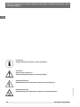
Information!
This symbol provides you with information, notes and tips.
Caution!
General point of hazard! Please heed the operating instructions.
Danger!
Hazard of personal injury through electric voltage.
Danger!
Hazard of personal injury through high temperatures.
Temperature Dry Well Calibrators/Micro Calibration Baths Page 2 - 39
Kalibrator temperatury z suchym otworem pomiarowym / Strona 40 - 80
Kalibrator kąpielowy - mikro

3
1. Device Description and Intended Use 4
2.
Safety Instructions 6
3.
Unpacking and Inspecting the Delivery 8
4. Description of the Controls 9
5. Start-up of the Calibrator/Micro Calibration Bath 11
6. Operating the Calibrator/Micro Calibration Bath 14
7. Error Messages 25
8. Cooling Down of the Metal Block/Liquid Bath 25
9. Cleaning and Maintenance 26
10. Warranty and Repairs 26
11. Recalibrating 26
12.
Decommissioning and Disposal 27
13.
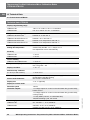
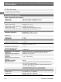
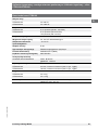
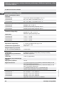
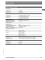
Technical Data 28
WIKA Service 80
GB
Contents
Temperature Dry Well Calibrators/Micro Calibration Baths
CTD9100/CTB9100
11263911 04/2007 GB/D
WIKA Operating Instructions Temperature Dry Well Calibrators/Micro Calibration Baths

GB
Temperature Dry Well Calibrators/Micro Calibration Baths
CTD9100/CTB9100
11263911 04/2007 GB/D
WIKA Operating Instructions Temperature Dry Well Calibrators/Micro Calibration Baths4
The calibrator/micro calibration bath is a portale unit
for service, industry and laboratory tasks. The WIKA
temperature calibrators/micro calibration baths are
intended to calibrate thermometers, temperature
switches/thermostats, resistance thermometers
and thermal elements. The operational safety of the
supplied instruments is only guaranteed if they are
operated according to their intended use (inspection
of temperature sensors). Specified limit values (see
“Technical Data”) should never be exceeded.
It is your responsibility to select the instrument
which is suitable for your specific application,
to connect it correctly, to carry out tests and to
maintain all the components.
Various instrument versions are manufactured.
The respective type label on the calibrator/micro
calibration bath displays the version of each device.
These operating instructions apply to the following
calibrator/micro calibration bath types:
1. Device Description and Intended Use
Temperature calibrators
CTD9100-165 (cooling and heating)
CTD9100-450 (heating)
CTD9100-650 (heating)
Micro calibration baths
CTB9100-165 (cooling and heating)
CTB9100-225 (heating)
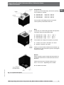
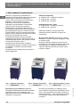
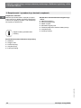
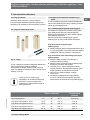
The calibrator/micro calibration bath consists of a
rugged grey and blue steel housing with carrying
handle.
The rear part of the housing contains a metal
block/liquid bath with a hole, accessible from the
top, for the test specimen fixture.
The heating or cooling elements and the
temperature sensor for determining the reference
temperature are integrated in the metal block/liquid
bath.
The metal block/liquid bath is heat insulated.
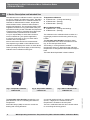
Fig. 1: Temperature calibrator
CTD9100-650
Fig. 2: Temperature calibrator
CTD9100-165
Fig. 3: Micro calibration bath
CTB91000-165
The front part of the housing contains the com-
plete electronic unit for controlling the reference
temperature.
Solid state relays (SSR) are used to control the
heating and cooling elements.
A controller equipped with a 7-segment LED
(2 lines, 4 digits) for the reference and set
temperature is located on the front plate.
The micro calibration bath also has a thumb wheel
for controlling the stirring speed.

5
GB
Temperature Dry Well Calibrators/Micro Calibration Baths
CTD9100/CTB9100
11263911 04/2007 GB/D
WIKA Operating Instructions Temperature Dry Well Calibrators/Micro Calibration Baths
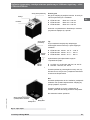
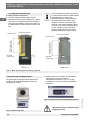
Front and top
At the top you will find the dry well access opening
for the inserts for models:
CTD9100-165: Ø 28 mm x 150 mm
CTD9100-450: Ø 60 mm x 150 mm
CTD9100-650: Ø 28 mm x 150 mm
The controller with display and the four button
control pad are positioned at the front.
Rear
At the rear you will find the type label with important
information about the individual model:
CTD9100-165: range -30 °C ...+165 °C
CTD9100-450: range 40 °C ... 450 °C
CTD9100-650: range 40 °C ... 650 °C
The suitable line voltage and frequency is printed:
115 VAC, 50...60 Hz or 230 VAC, 50...60 Hz
100 VAC...240 VAC, 50...60 Hz
Further you will find the individual serial number, e.g.
S/N 550 33 44, the instrument‘s power consumption
and the fuse rating.
Bottom
Mains connector, power switch and fuse holder are
positioned at the bottom of the instrument close to
the front.
Furthermore the fans air inlet(s) can be found
there - one or two - depending on the model.
Do not obstruct air inlets.
Fig. 4: Component description

GB
Temperature Dry Well Calibrators/Micro Calibration Baths
CTD9100/CTB9100
11263911 04/2007 GB/D
WIKA Operating Instructions Temperature Dry Well Calibrators/Micro Calibration Baths6
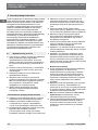
2. Safety Instructions
Always read the operating instructions carefully
prior to using the new product. Always adhere to the
instructions contained herein, especially the safety
instructions; otherwise, there is a potential risk of
operator injury and damage to the calibrator and the
sensors being tested.
Even though WIKA provides assistance for the use
of the product through personal consultation or the
respective literature, it is the responsibility of the
customer to determine the suitability of the product
for the specific application.
The temperature calibrator/micro calibration bath
is a state-of-the-art device. This relates to the
accuracy, functioning and the safe operation of
the calibrator/micro calibration bath. However,
professional and safety conscious conduct of the
operator is required to ensure safe operation.
2.1 Qualified personnel
The personnel entrusted with start-up, operation
and maintenance of the calibrator/micro
calibration bath have to be suitably qualified; the
required knowLEDge can be gained via train-
ing courses or appropriate on-the-job instruc-
tion. The personnel have to be familiar with the
contents of these instructions, which have to be
available to them at all times.
·The electrical connection should only be carried
out by a fully qualified electrician.
·All work has to be carried out in accordance
with existing national regulations on accident
prevention and safety at work and with any
internal regulations of the operator, even if they
are not specified in these instructions.
Always observe the safety information contained
in these operating instructions.
2.2 Basic safety regulations
·Only operate the calibrator/micro calibration bath
when it is in correct, fully functional condition.
The calibrator/micro calibration bath is energized
with hazardous voltages via a mains cable.
Improper use can result in personal injuries.
Correct and safe operation of the calibrator/
micro calibration bath demands correct
transport, storage, installation and assembly,
as well as proper use and careful operation and
maintenance.
The calibrator/micro calibration bath should only
be used for its intended purpose. Furthermore,
hazardous media should not be used and all
technical specifications have to be observed.
If faults cannot be cleared, immediately shut
down the calibrator/micro calibration bath and
ensure that it cannot be started up accidentally.
Repairs should only be carried out by the
manufacturer. Tampering with or modifying
the calibrator/micro calibration bath is strictly
prohibited.
Prior to replacing the safety fuse, always de-
energize the calibrator/micro calibration bath
completely by disconnecting the mains cable
from the mains outlet.
Ensure that the complete operating instructions
are always available in excellent condition at the
calibrator/micro calibration bath installation site.
Ensure that calibrator/micro calibration bath
operators receive regular instruction in the
various aspects of occupational health and
safety and environmental protection and have full
knowLEDge of these operating instructions and
the safety information contained herein.
·
Thermal fuse
For protection purposes, the calibrator/micro
calibration bath is equipped with an autonomous
thermal fuse, which interrupts the power supply
to the heater if the temperature exceeds a
certain value inside the housing. Once the
metal bock/liquid bath has cooLED down,
the calibrator/micro calibration bath has to be
returned to WIKA for inspection.
The calibrator/micro calibration bath has
been designed as a measurement and control
instrument. If the calibrator/micro calibration
bath is used for purposes not expressly specified
in these operating instructions, additional safety
measures have to be taken.
The calibrator/micro calibration bath should NOT
be used in explosive atmospheres without
appropriate protection (flammable or explosive
atmospheres).
If malfunctioning of the calibrator/micro
calibration bath can result in personal injuries
or damage to property, the system has to be
protected with additional electromechanical
protective equipment.

7
GB
Temperature Dry Well Calibrators/Micro Calibration Baths
CTD9100/CTB9100
11263911 04/2007 GB/D
WIKA Operating Instructions Temperature Dry Well Calibrators/Micro Calibration Baths
2.3 Safety instructions for the application of
calibration liquids
Calibration liquid water:
Only use distilLED water, otherwise excessive
limescale and soiling will build up in the
calibrator tank.
Calibration liquid silicone oil:
Only use the silicone oil recommended in these
operating instructions.
Always read the safety data sheet supplied with
the silicone oil before using it.
Always ensure adequate ventilation when
working with silicone oil, since hazardous
substances can be released.
Prevent silicone oil from coming into contact with
your eyes.
Since silicone oil is hygroscopic, always use the
transport lid to close the calibration bath after
use.
The transport lid is equipped with a safety
valve. If the micro calibration bath is closed
when warm, impermissible pressure can build
up. In order to prevent excess pressure which
can destroy the liquid bath, the safety valve is
activated once the pressure reaches approx. 2.5
bar. This can result in hot steam being released.
Risk of severe burns!
Prior to transport or contact with
the metal block/liquid bath ensure
that it has cooLED down sufficiently,
otherwise there is a risk of severe
burns caused by the metal block/
liquid bath and the test specimen.
If problems or questions arise, please contact your
supplier or the manufacturer directly:
Alexander Wiegand GmbH & Co. KG
Alexander-Wiegand-Straße, 63911 Klingenberg,
Germany
Tel: +49 9372 132 9986, Fax: +49 09372 132 217
Email: [email protected], www.wika.de

GB
Temperature Dry Well Calibrators/Micro Calibration Baths
CTD9100/CTB9100
11263911 04/2007 GB/D
WIKA Operating Instructions Temperature Dry Well Calibrators/Micro Calibration Baths8
3. Unpacking and Inspecting the Delivery
Unpack your calibrator/micro calibration bath.
The calibrator/micro calibration bath is delivered
in special protective packaging. Keep this
protective packaging for sending the instrument for
recalibration or repairs to the manufacturer.
Inspect the delivery first.
Standard delivery temperature calibrator:
Calibrator
Sleeve remover
Mains connection cable
Test certificate
Operating instructions
Standard delivery micro calibration bath:
Calibration bath
Transport lid
Sensor cage
Magnetic stirrer
Mains connection cable
Test certificate
Operating instructions

9
GB
Temperature Dry Well Calibrators/Micro Calibration Baths
CTD9100/CTB9100
11263911 04/2007 GB/D
WIKA Operating Instructions Temperature Dry Well Calibrators/Micro Calibration Baths
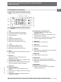
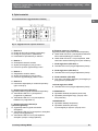
4. Description of the Controls
4.1 Front of the controller (controller type TLK
32)
1 P key
Accessing the default set temperature
Accessing menu items and parameters
Confirming inputs
2 key
Reducing the setting values
Selecting individual menu items
Returning to the previous menu level
3 5 key
Increasing the setting values
Selecting individual menu items
Returning to the previous menu level
4 U key
Retrieving the saved set temperatures (only for
the S version)
5 LED OUT 1
Signals the status of the output for the
temperature control
If the LED OUT 1 lights up, the calibrator/micro
calibration bath is heating
If the LED OUT 1 does not light up, the calibra-
tor/micro calibration bath is not heating
6 LED OUT 2
a) Heating instrument
Signals the status of the output for the fan
control
If the LED OUT 2 lights up, the fan is running at
high speed
If the LED OUT 2 does not light up, the fan is
running at low speed
Fig. 5: Overview of the controls on the front of the
controller
b) Heating and cooling instrument
Signals the status of the output for the
temperature control
If the LED OUT 1 lights up, the calibrator/micro
calibration bath is cooling
If the LED OUT 1 does not light up, the calibra-
tor/micro calibration bath is not cooling
7 LED OUT 3
This LED has no function here
8 LED OUT 4
This LED has no function here
9 LED SET
When flashing, it signals access to the individual
menu items and parameters
10 LED AT/ST
This LED has no function here
11 PV indicator
Displays the current reference temperature
Displays the individual modes, menu items and
parameters
12 SV indicator
Displays the set temperature
Displays certain parameters in the individual
modes and menu items

GB
Temperature Dry Well Calibrators/Micro Calibration Baths
CTD9100/CTB9100
11263911 04/2007 GB/D
WIKA Operating Instructions Temperature Dry Well Calibrators/Micro Calibration Baths10
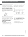
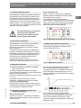
4.2 Data interface
The S version is equipped with a serial communica-
tion interface RS-485. It is possible to connect a
PC, a level converter or a network via this interface.
The utilized software protocol is a MODBUS-RTU
protocol, which is used in numerous market-avail-
able monitoring programs.
The transfer rate (baud rate) is factory set to 9600
baud. Other transfer rates are available on request.
The 5-pole socket is provided with two connections,
A and B, which have to be connected to the
respective sockets of the PC, the level converter or
the network.
To enable connection to a PC, the RS-485 signals
have to be externally converted into RS-232 or USB
signals. Appropriate converters including drivers
are optionally available. The PC records all the
operating data and enables the programming of all
the calibrator’s configuration parameters.
The minimum requirements for operation with a
USB converter are:
IBM compatible PC,
An instalLED Windows operating system
98SE, ME, 2000 or Windows XP (Home or
Professional),
A free USB port (USB 1.1 or USB 2.0).
Fig. 6: Top view of the 5-pole socket
A network configuration allows the connection of up
to 32 calibrators/micro calibration baths to the same
network.
Certain factory settings have to be carried out to
enable configuration of a network. In this case,
please contact your supplier or WIKA directly.
If you access the programming via the
keypad while communication via a
serial interface is running, the message
“buSy“ appears on the display.
4.3 Transmission protocol
The transmission protocol is supplied as an
additional document upon request.
Fig. 7: Network configuration

11
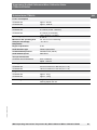
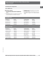
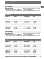
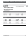
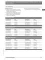
Calibration Range Flash point
DistilLED water 5 °C to 90 °C n.a.
Dow Corning 200 fluid with 5 CS -40 °C to 123 °C 133 °C
Dow Corning 200 fluid with 10 CS -35 °C to 155 °C 165 °C
Dow Corning 200 fluid with 20 CS 7 °C to 220 °C 230 °C
Dow Corning 200 fluid with 50 CS 25 °C to 270 °C 280 °C
GB
Temperature Dry Well Calibrators/Micro Calibration Baths
CTD9100/CTB9100
11263911 04/2007 GB/D
WIKA Operating Instructions Temperature Dry Well Calibrators/Micro Calibration Baths
5. Start-up of the Calibrator/Micro Calibration Bath
5.1 Operating position
The calibrator/micro calibration bath has to be
placed in a vertical standing position for operation,
this position guarantees optimum temperature
distribution in the metal block/liquid bath.
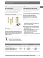
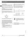
5.2 Sleeves for the metal block
In order to achieve the best possible accuracy, the
utilization of exactly fitting sleeves is necessary. The
diameter of the test specimen has to be determined
precisely. The bore in the sleeve results from the
addition of +0.5 mm.
Remove the sleeves after use with
the aid of the sleeve remover, and
remember to clean the sleeve and
the block. This prevents the sleeves
becoming jammed in the heating block.
Fig. 8: Sleeves
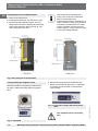
5.3 Preparing the micro calibration bath
In order to achieve the best possible accuracy of
a micro calibration bath, it has to be filLED with a
suitable calibration liquid.
5.3.1 Characteristics of the calibration liquids
Different calibration liquids supply varying
calibration results due to their specific
characteristics. Adjustment to the respective
calibration liquid has to be carried out by the
manufacturer.
We recommend the following calibration liquids for
the various temperature ranges:
When using water as the calibration liquid:
Only use distilLED or demineralised water,
otherwise excessive limescale and soiling will
build up in the calibrator tank.
When using silicone oil as the calibration liquid:
Only use the silicone oil recommended in these
operating instructions.
Always read the safety data sheet supplied with
the silicone oil before using it.
Always ensure adequate ventilation when
working with silicone oil, since hazardous
substances can be released.
Prevent silicone oil from coming into contact with
your eyes.
Since silicone oil is hygroscopic, always use the
transport lid to close the calibration bath after
use.

GB
Temperature Dry Well Calibrators/Micro Calibration Baths
CTD9100/CTB9100
11263911 04/2007 GB/D
WIKA Operating Instructions Temperature Dry Well Calibrators/Micro Calibration Baths12
The transport lid is equippe with a
safety valve. If the micro calibration
bath is closed when warm,
impermissible pressure can build up. In
order to prevent excess pressure which
can destroy the liquid bath, the safety
valve is activated once the pressure
reaches approx. 2.5 bar. This can result
in hot steam being released.
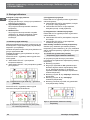
5.3.3 Operating the magnetic stirrer
The best possible homogeneity is achieved by
stirring the calibration liquid with the magnetic
stirrer.
Set the stirring speed to the respective max.
speed. Turn the thumb wheel (Fig. 11) upwards
to increase and downwards to decrease the
stirring speed.
The magnetic stirrer is a wearing
part.
Fig. 10: Liquid bath
Fig. 11: Front of the controller with stirring speed
wheel
5.3.2 Filling the micro calibration bath
Remove the transport lid.
Insert the test specimen into the sensor cage.
Fill the tank with calibration liquid. The max.
filling level in the tank is displayed by the upper
edge of the aluminium lining (see Fig. 9). The
max. filling level is 0.5 litres.
Fig. 9: Max. filling level of the liquid bath

13
GB
Temperature Dry Well Calibrators/Micro Calibration Baths
CTD9100/CTB9100
11263911 04/2007 GB/D
WIKA Operating Instructions Temperature Dry Well Calibrators/Micro Calibration Baths
5.4 Testing temperature sensors
A separate temperature measuring instrument
connected to the test specimen is required to
test the temperature sensors. By comparing the
temperature displayed at the external measur-
ing instrument with the reference temperature it is
possible to assess the status of the test specimen.
Remember that the test specimen requires a short
period of time until it absorbs the temperature of the
metal block or liquid bath.
It is not possible to calibrate
earthed thermal elements, because
the heating block is earthed and
any measurement would produce
incorrect results.
5.5 Start-up procedure
If the calibrator is not used for a longer period, it is
possible for moisture to enter the heating elements
due to the material used (magnesium oxide).
After calibrator transport or storage in a damp
environment, the heating elements have to be gently
brought up to operating temperature. During the
drying out procedure it has to be assumed that
the calibrator has not yet achieved the required
insulation voltage for protection class I.
The start-up set value is T
start
=120°C for a stop
period of T
n
=15 min.
5.6 Switching on the calibrator/micro
calibration bath
Connect the supplied mains plug to a mains
outlet.
Actuate the mains switch.
The controller is initialized
tESt appears on the upper PV display.
The version number, e.g. rL 2.2, appears on the
lower SV display.
Initialization is completed after approx. 5 sec., the
calibration mode is then automatically displayed.
The instalLED heating and cooling elements
automatically adjust the metal block from the
room temperature to the set temperature set at the
controller.
5.7 Reference and set temperature display
Upper PV display:
The red, 4-digit, 7-segment display shows the
current temperature of the metal block/liquid bath.
Lower SV display:
The green, 4-digit, 7-segment display shows the
current set temperature of the metal block/liquid
bath.
Once the set temperature has been achieved, the
radiated heat energy from the metal block/liquid
bath is supplied by short firing pulses, thus ensuring
that the temperature inside is kept constant.
5.8 Stabilizing the reference temperature
The switch on time of the heater is displayed by the
red LED OUT 1.
During the heating up phase a constantly lit LED
displays the supply of heat energy, a flashing LED
indicates that the reference temperature has almost
reached the set temperature and the heat energy is
now being supplied at short intervals.
In order to guarantee excellent temperature stability,
the cycle time of the controller is set to low and the
control output is addressed on a regular basis.
Fig. 12: Reference and set temperature display
Fig. 13: LED OUT 1 displays
Fig. 14: Control occurs via PID algorithm

GB
Temperature Dry Well Calibrators/Micro Calibration Baths
CTD9100/CTB9100
11263911 04/2007 GB/D
WIKA Operating Instructions Temperature Dry Well Calibrators/Micro Calibration Baths14
6. Operating the Calibrator/Micro Calibration Bath
Three operating modes are available:
·
Calibration mode
This is the normal operating mode in which the
calibration of test specimens is carried out.
·
Set value mode
The set temperatures can be entered in this
mode.
·
Main menu
All the settings can be carried out in this mode,
e.g. presetting the set temperatures or setting
the control parameters.
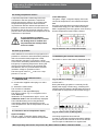
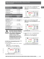
6.1 Calibrating (calibration mode)
The calibrator/micro calibration bath is automatically
in calibration mode as soon as it has been switched
on and after initialization.
The current reference temperature is displayed by
the upper PV display.
The set temperature is displayed by the lower SV
display.
The LED OUT 1 indicates the status of the output
for the heater control:
If LED OUT 1 lights up, the temperature is being
increased.
·If LED OUT 1 does not light up, the heater is
switched off.
Fig. 15: Calibration mode HEATING displays
The LED OUT 2 indicates the status of the output
for the fan/cooling control:
Fig. 16: Calibration mode FAN or COOLING displays
a) Heating instrument
The LED OUT 2 indicates the status of the output
for the fan control:
·If the LED OUT 2 lights up, the fan is running at
high speed.
·If the LED OUT 2 does not light up, the fan is
running at low speed.
b) Heating and cooling instrument
The LED OUT 2 indicates the status of the output
for the cooling control:
·If LED OUT 2 lights up, the temperature is being
decreased.
·If LED OUT 2 does not light up, cooling is
switched off.
There are two ways to set the set temperature:
Either you set a temporary set temperature (see
section 6.2) or you save fixed set temperatures in
the main menu (see section 6.3).
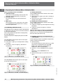
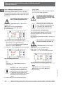
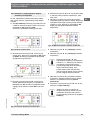
6.2 Setting a temporary set temperature (set
value mode)
In this operating mode it is possible to temporarily
modify a saved set temperature.
Press the P key.
The currently active set value memory, e.g. SP2
(set point 2), is displayed by the upper PV
display. The respective set temperature is
displayed by the lower SV display.
Press the 5 key to increase the set tempera-
ture.
Press the key to decrease the set
temperature.
Press the P key again to confirm the new set
value.
Fig. 17: Temporary set temperature setting

15
GB
Temperature Dry Well Calibrators/Micro Calibration Baths
CTD9100/CTB9100
11263911 04/2007 GB/D
WIKA Operating Instructions Temperature Dry Well Calibrators/Micro Calibration Baths
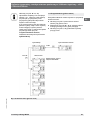
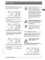
6.3 Programming (main menu)
All the settings can be carried out in this menu
structure.
Press the P key for approx. 5 seconds. The main
menu opens.
Use the and 5 keys to select the desired
main menu (see overview).
Press the P key to confirm the selected menu
item.
Fig. 18: Menu structure (main menu)
Press the 5 and key to raise and
lower the value by 0.1 respectively.
If the keys are held pressed for at
least one second, the value increases
or decreases quickly and after two
seconds even more quickly; this means
the desired value can be reached
rapidly. ·If no key is pressed in the set
value mode for approx. 15 seconds,
the device automatically returns to the
calibration mode.

GB
Temperature Dry Well Calibrators/Micro Calibration Baths
CTD9100/CTB9100
11263911 04/2007 GB/D
WIKA Operating Instructions Temperature Dry Well Calibrators/Micro Calibration Baths16
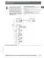
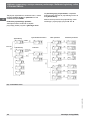
As displayed by the menu structure, it is possible to
reach the group and parameter levels to carry out
settings via OPEr.
Returning to another level
If no key is pressed in the main menu at the group
or parameter level for approx. 15 seconds, the
device automatically returns to the previous level up
to the calibration mode.
You can also return to a previous level by pressing
and holding the or 5 key.
Fig. 19: Menu structure

17
GB
Temperature Dry Well Calibrators/Micro Calibration Baths
CTD9100/CTB9100
11263911 04/2007 GB/D
WIKA Operating Instructions Temperature Dry Well Calibrators/Micro Calibration Baths
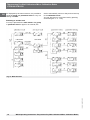
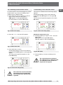
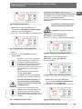
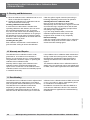
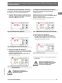
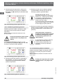
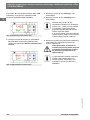
6.3.1 Switching off the automatic control
For certain tasks it can be advantageous to switch
off the control, e.g. to carry out settings at the
calibrator/micro calibration bath.
Press the P key when in calibration mode for
approx 5 sec., the main menu opens.
OPEr appears on the upper PV display
LED SET flashes on the lower
SV display.
Press the 5 or key until OFF appears.
Press the P key to confirm.
An alternating display of the current reference
temperature and OFF appears on the upper PV
display
The current set temperature appears on the
lower SV display.
The control has now been switched
off and the reference temperature
will constantly drop without being
regulated.
Fig. 20: Main menu display
Fig. 21: Menu control OFF
Fig. 22: Control OFF setting display
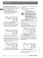
6.3.2 Switching on the automatic control
The control is switched off if the following display
appears:
An alternating display of the current reference
temperature and OFF appears on the upper PV
display.
The current set temperature appears on the lower
SV display.
Fig. 24: rEG display
Fig. 23: Control OFF setting display
Switch the control back on by:
Pressing the P key for approx. 5 sec., the main
menu opens.
rEG appears on the upper PV display
LED SET flashes on the lower
SV display.
Press the P key to confirm switching on the
control.
The control has been reactivated.
The calibrator/micro calibration bath
is in calibration mode and the set
temperature is targeted.

GB
Temperature Dry Well Calibrators/Micro Calibration Baths
CTD9100/CTB9100
11263911 04/2007 GB/D
WIKA Operating Instructions Temperature Dry Well Calibrators/Micro Calibration Baths18
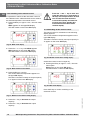
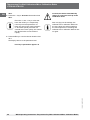
6.3.3 Switching on the manual control
It is possible to switch off the automatic control of
the calibrator/micro calibration bath and to achieve
the desired temperature via manual control.
Press the P key for approx 5 sec., the main menu
opens.
OPEr appears on the upper PV display.
LED SET flashes on the lower
SV display.
Press the 5 or key until OPLO appears
OPLO appears on the upper PV display.
LED SET flashes on the lower
SV display.
Press the P key to confirm.
The current reference temperature appears on
the upper PV display.
The letter H and the currently set output capacity
in % appear on the lower SV display.
Fig. 25: Main menu display
Fig. 26: Menu manual control OPLO
Fig. 27: Manual control OPLO setting display
Press the 5 key, to increase the output
capacity.
Press the key, to decrease the output
capacity.
Press the 5 and key to raise and
lower the value by 0.1 respectively. If
the keys are held pressed for at least
one second, the value increases
or decreases quickly and after two
seconds even more quickly; this
means the desired value can be
reached rapidly.
6.3.4 Switching off the manual control
The manual control is switched on if the following
display appears:
The current reference temperature appears on the
upper PV display.
The letter H and the currently set output capacity in
% appear on the lower SV display.
Fig. 28: Manual control OPLO setting display
Fig. 29: Main menu display
Switch the manual control off again by
Pressing the P key for approx. 5 sec., the main
menu opens.
rEG appears on the upper PV display.
LED SET flashes on the lower
SV display.
Press the P key to confirm switching on the
automatic control.

19
GB
Temperature Dry Well Calibrators/Micro Calibration Baths
CTD9100/CTB9100
11263911 04/2007 GB/D
WIKA Operating Instructions Temperature Dry Well Calibrators/Micro Calibration Baths
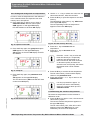
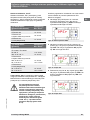
6.3.5 Setting and saving fixed set temperatures
In order to save set temperatures in the calibrator/
micro calibration bath, the respective set value
memory has to be opened.
Press the P key for approx 5 sec. when in
calibration mode, the main menu opens.
OPEr appears on the upper PV display.
LED SET flashes on the lower
SV display.
Press the P key again, the group level opens.
OPEr appears on the upper PV display.
’SP appears on the lower SV display and LED
SET flashes.
Press the P key again, the parameter level
opens.
’SP appears on the upper PV display.
The set value memory SP1 and LED SET flash
on the lower SV display.
Fig. 30: Operator menu OPEr
Fig. 31: Group SP
Fig. 32: Parameter for the set memory SP1
Use the 5 or key to select one of the four set
value memories SP1, SP2, SP3 and SP4.
Press the P key to open the respective set value
memory.
The selected set value memory, e.g. SP3 flashes
on the upper PV display.
The corresponding current set temperature
appears on the lower SV display.
Press the 5 key to increase the set
temperature.
Press the key to decrease the set
temperature.
Press the 5 and key to raise and
lower the value by 0.1 respectively.
If the keys are held pressed for at
least one second, the value increases
or decreases quickly and after two
seconds even more quickly; this means
the desired value can be reached
rapidly.
Press the P key to confirm the set temperature.
The set value memory closes and the display
returns to the parameter level.
Press and hold the or 5 key to return to the
calibration mode.
If no key is pressed for approx. 15
seconds, the device automatically
returns to a previous level up to the
calibration mode.
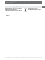
6.3.6 Retrieving the saved set temperatures
The saved set temperatures can be retrieved in
calibration mode.
Press the U key for approx 2 sec., the current set
value memory opens.
The current reference temperature appears on
the upper PV display.
The set value memory SP1, SP2, SP3 or SP4
appears on the lower SV display for 2 sec.
followed by the current set temperature.
Fig. 33: Set value memory SP3 entry

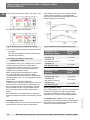
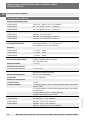
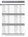
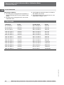
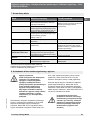
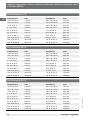
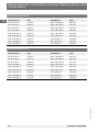
Calibrator type
(heating/cooling)
Setting for
“SLor”
CTD9100-165 < 7 °C/min
CTB9100-165
with silicone oil 20 CS
< 3 °C/min
CTB9100-165
with distilLED water
< 5 °C/min
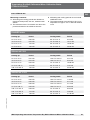
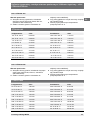
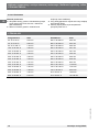
Calibrator type
(heating)
Setting for
“SLor”
CTD9100-450, -650 < 35 °C/min
CTB9100-225
with silicone oil 20 CS
< 22 °C/min
CTB9100-225
with distilLED water
< 12 °C/min
GB
Temperature Dry Well Calibrators/Micro Calibration Baths
CTD9100/CTB9100
11263911 04/2007 GB/D
WIKA Operating Instructions Temperature Dry Well Calibrators/Micro Calibration Baths20
Firstly, the set value memory SP1, SP2, SP3 or SP4
Fig. 34: Retrieving the set temperatures display
Secondly, the saved set temperature
To receive another saved set value, press the U
key again.
The selected temperature value is immediately
adopted and targeted.
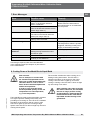
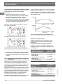
6.3.7 Setting a gradient control and a
temperature profile
It is possible to carry out a gradient control yourself
and thus determine the time in which the set
temperature is reached. The time can be shorter
or longer than the time usually required by the
calibrator/micro calibration bath.
When modifying the set temperature or switch-
ing on the calibrator/micro calibration bath it
is automatically determined which of the gradients
(heating gradient “SLor” or cooling gradient “SLoF”)
is to be used.
Additionally, you can ensure that the
calibrator/micro calibration bath switches to the set
temperature in set value memory SP2 as soon as
the set temperature in set value memory SP1 has
been achieved and after a programmed duration
time “dur.t”; this creates a simple temperature
profile.
After switching on the calibrator/micro calibration
bath the temperature profile is automatically carried
out.
Heating gradient “SLor”
The heating gradient “SLor“ is active if the reference
temperature is lower than the set temperature.
Each calibrator type has a max. heating capacity,
meaning that only settings < than this heating
capacity are reasonable and extend the time until
the set temperature is achieved.
Fig. 35: Gradient control and temperature profile
Cooling gradient “SLoF“
The cooling gradient “SLor“ is active if the reference
temperature is higher than the set temperature.
Only settings below the cooling capacity of the
calibrator have an effect on the cooling gradients.
The duration time “dur.t“ is active if the set
temperature SP1 has been achieved. Subsequently,
the calibrator/micro calibration bath automatically
switches to set temperature SP2.
Strona się ładuje...
Strona się ładuje...
Strona się ładuje...
Strona się ładuje...
Strona się ładuje...
Strona się ładuje...
Strona się ładuje...
Strona się ładuje...
Strona się ładuje...
Strona się ładuje...
Strona się ładuje...
Strona się ładuje...
Strona się ładuje...
Strona się ładuje...
Strona się ładuje...
Strona się ładuje...
Strona się ładuje...
Strona się ładuje...
Strona się ładuje...
Strona się ładuje...
Strona się ładuje...
Strona się ładuje...
Strona się ładuje...
Strona się ładuje...
Strona się ładuje...
Strona się ładuje...
Strona się ładuje...
Strona się ładuje...
Strona się ładuje...
Strona się ładuje...
Strona się ładuje...
Strona się ładuje...
Strona się ładuje...
Strona się ładuje...
Strona się ładuje...
Strona się ładuje...
Strona się ładuje...
Strona się ładuje...
Strona się ładuje...
Strona się ładuje...
Strona się ładuje...
Strona się ładuje...
Strona się ładuje...
Strona się ładuje...
Strona się ładuje...
Strona się ładuje...
Strona się ładuje...
Strona się ładuje...
Strona się ładuje...
Strona się ładuje...
Strona się ładuje...
Strona się ładuje...
Strona się ładuje...
Strona się ładuje...
Strona się ładuje...
Strona się ładuje...
Strona się ładuje...
Strona się ładuje...
Strona się ładuje...
Strona się ładuje...
-
 1
1
-
 2
2
-
 3
3
-
 4
4
-
 5
5
-
 6
6
-
 7
7
-
 8
8
-
 9
9
-
 10
10
-
 11
11
-
 12
12
-
 13
13
-
 14
14
-
 15
15
-
 16
16
-
 17
17
-
 18
18
-
 19
19
-
 20
20
-
 21
21
-
 22
22
-
 23
23
-
 24
24
-
 25
25
-
 26
26
-
 27
27
-
 28
28
-
 29
29
-
 30
30
-
 31
31
-
 32
32
-
 33
33
-
 34
34
-
 35
35
-
 36
36
-
 37
37
-
 38
38
-
 39
39
-
 40
40
-
 41
41
-
 42
42
-
 43
43
-
 44
44
-
 45
45
-
 46
46
-
 47
47
-
 48
48
-
 49
49
-
 50
50
-
 51
51
-
 52
52
-
 53
53
-
 54
54
-
 55
55
-
 56
56
-
 57
57
-
 58
58
-
 59
59
-
 60
60
-
 61
61
-
 62
62
-
 63
63
-
 64
64
-
 65
65
-
 66
66
-
 67
67
-
 68
68
-
 69
69
-
 70
70
-
 71
71
-
 72
72
-
 73
73
-
 74
74
-
 75
75
-
 76
76
-
 77
77
-
 78
78
-
 79
79
-
 80
80


WIKA CTD9100-650 Operating Instructions Manual
- Typ
- Operating Instructions Manual
- Niniejsza instrukcja jest również odpowiednia dla
w innych językach
- English: WIKA CTD9100-650
Powiązane artykuły
Inne dokumenty
-
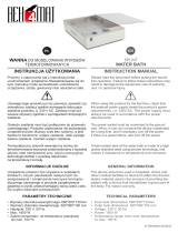 REH4MAT Splint water bath Instrukcja obsługi
-
LG 19HK312C-B Skrócona instrukcja obsługi
-
Tyco Kendall Genius 2 Operation And Service Manual
-
IFM SI0521 Instrukcja obsługi
-
Overmax OV-X-BEE DRONE 3.3 WiFi Instrukcja obsługi
-
Roche cobas e 801 instrukcja obsługi
-
Moxa ioLogik R1200 Series Instrukcja obsługi
-
-
Seca mVSA 535 Instrukcja obsługi
-
Dell Latitude XT instrukcja
