Moxa ioLogik R1200 Series Instrukcja obsługi
- Typ
- Instrukcja obsługi

ioLogik R1200 Series User’s Manual
Edition 3.4, April 2021
www.moxa.com/product
© 2021 Moxa Inc. All rights res erved.

ioLogik R1200 Series User’s Manual
The software described in this manual is furnished under a license agreement and may be used only in accordance
with the terms of that agreement.
Copyright Notice
© 2021 Moxa Inc. All rights res erved.
Trademarks
The MOXA logo is a registered trademark of Moxa Inc.
All other trademarks or registered marks in this manual belong to their respective manufacturers.
Disclaimer
Information in this document is subject to change without notice and does not represent a commitment on the part of
Moxa.
Moxa provides this document as is, without warranty of any kind, either expressed or implied, including, but not
limited to, its particular purpose. Moxa reserves the right to make improvements and/or changes to this manual, or to
the products and/or the programs described in this manual, at any time.
Information provided in this manual is intended to be accurate and reliable. However, Moxa assumes no responsibility
for its use, or for any infringements on the rights of third parties that may result from its use.
This product might include unintentional technical or typographical errors. Changes are periodically made to the
information herein to correct such errors, and these changes are incorporated into new editions of the publication.
Technical Support Contact Information
www.moxa.com/support
Moxa Americas
Toll-free: 1-888-669-2872
Tel: +1-714-528-6777
Fax: +1-714-528-6778
Moxa China (Sha ngha i off ice)
Toll
-free: 800-820-5036
Tel:
+86-21-5258-9955
Fax:
+86-21-5258-5505
Moxa Europe
Tel: +49-89-3 70 03 99-0
Fax: +49-89-3 70 03 99-99
Moxa As ia-P ac if ic
Tel:
+886-2-8919-1230
Fax:
+886-2-8919-1231
Moxa Ind ia
Tel: +91-80-4172-9088
Fax: +91-80-4132-1045

Table of Contents
1. Overview ..................................................................................................................................... 1-1
Introduction ................................................................................................................................. 1-2
Product Features........................................................................................................................... 1-2
Package Checklist ......................................................................................................................... 1-2
Product Model Information.............................................................................................................. 1-2
Ordering Information .............................................................................................................. 1-2
Specifications ............................................................................................................................... 1-3
Common Specifications ........................................................................................................... 1-3
ioLogik R1210 ....................................................................................................................... 1-4
ioLogik R1212 ....................................................................................................................... 1-4
ioLogik R1214 ....................................................................................................................... 1-5
ioLogik R1240 ....................................................................................................................... 1-6
ioLogik R1241 ....................................................................................................................... 1-6
Physical Dimensions ...................................................................................................................... 1-7
Hardware Reference ...................................................................................................................... 1-7
Panel Guide .......................................................................................................................... 1-7
LED Indicators ....................................................................................................................... 1-8
Switch Settings ..................................................................................................................... 1-8
DI Circuit Diagram ................................................................................................................. 1-8
DIO Circuit Diagram ............................................................................................................... 1-9
Relay Circuit Diagram ............................................................................................................ 1-10
AI Circuit Diagram ................................................................................................................ 1-10
2. Initia l Setup ................................................................................................................................. 2-1
Hardware Installation .................................................................................................................... 2-2
Connecting the Power ............................................................................................................. 2-2
Grounding the ioLogik R1200 ................................................................................................... 2-2
Connecting to Serial Interface .................................................................................................. 2-2
Mounting the ioLogik R1200 ..................................................................................................... 2-2
Connecting to Digital Sensors and Devices ................................................................................. 2-3
RS-485 Networks ................................................................................................................... 2-4
Modbus/RTU Devices .............................................................................................................. 2-5
Dual RS-485 or Repeater Settings............................................................................................. 2-5
Jumper Settings (DIO and AI) .................................................................................................. 2-6
Pull High/Low DIP Switch Settings for the RS-485 Port ................................................................. 2-6
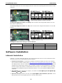
Software Installation ..................................................................................................................... 2-7
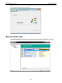
ioSearch Installation ............................................................................................................... 2-7
Initial Setup by USB ............................................................................................................... 2-9
Restore Factory Default Settings.............................................................................................. 2-10
3. Us in g io Search ............................................................................................................................. 3-1
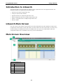
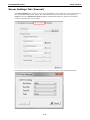
Introduction to ioSearch ................................................................................................................. 3-2
ioSearch Main Screen .................................................................................................................... 3-2
Main Screen Overview ................................................................................................................... 3-2
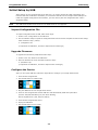
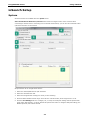
ioSearch Setup ............................................................................................................................. 3-3
Sys tem ................................................................................................................................ 3-3
Sort ..................................................................................................................................... 3-5
Help .................................................................................................................................... 3-6
Quick Links .................................................................................................................................. 3-6
Main Functions ............................................................................................................................. 3-6
Locate.................................................................................................................................. 3-6
Connect/Disconnect................................................................................................................ 3-6
Firmwa re Upgrade.................................................................................................................. 3-7
Import ................................................................................................................................. 3-7
Export.................................................................................................................................. 3-7
Change Server Name.............................................................................................................. 3-7
Restart System...................................................................................................................... 3-8
Delete ioLogik Device ............................................................................................................. 3-8
Reset to Default..................................................................................................................... 3-8
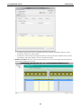
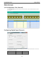
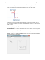
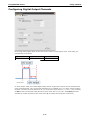
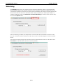
Main Screen ................................................................................................................................. 3-9
I/O Configuration Tab (General) ............................................................................................... 3-9
Configuring Digital Input Channels ............................................................................................ 3-9
Configuring Digital Output Channels ......................................................................................... 3-11
Configuring Analog Input Channels .......................................................................................... 3-13
AI Input Range ..................................................................................................................... 3-13
Configuring Analog Output Channels ........................................................................................ 3-14
Server Info Tab ........................................................................................................................... 3-16
Server Settings Tab (General) ................................................................................................. 3-17
Watchdog ............................................................................................................................ 3-18

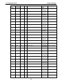
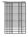
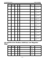
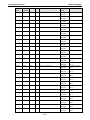
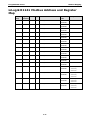
A. Modbus Mapping .......................................................................................................................... A-1
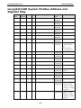
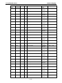
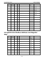
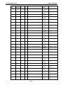
ioLogik R1200 System Modbus Address and Register Map .................................................................... A-2
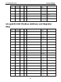
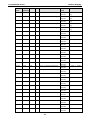
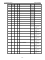
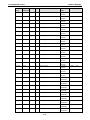
ioLogik R1210 Modbus Address and Register Map ............................................................................... A-3
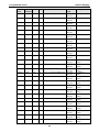
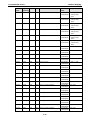
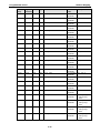
ioLogik R1212 Modbus Address and Register Map ..............................................................................A-11
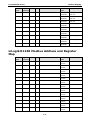
ioLogik R1214 Modbus Address and Register Map ..............................................................................A-24
ioLogik R1240 Modbus Address and Register Map ..............................................................................A-31
ioLogik R1241 Modbus Address and Register Map ..............................................................................A-37
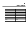
B. Factory Defaults ........................................................................................................................... B-1
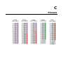
C. Pinouts ........................................................................................................................................ C-1
D. FCC Interference Statement .......................................................................................................... D-1
E. European Community (CE) ............................................................................................................ E-1

1
1. Overview
The following topics are covered in this chapter:
Introduction
Product Features
Package Checklist
Product Model Information
Ordering Information
Spe c if ica t io ns
Common Specifications
ioLogik R1210
ioLogik R1212
ioLogik R1214
ioLogik R1240
ioLogik R1241
Physica l Dimen sio ns
Hardware Reference
Panel Guide
LED Indicators
Switch Settings
DI Circuit Diagram
DIO Circuit Diagram
Relay Circuit Diagram
AI Circuit Diagram

ioLogik R1200 Series Overview
1-2
Introduction
The ioLogik R1200 is an industrial grade, wide-temperature serial remote I/O device equipped with dual RS-
485 ports that allow users t o select between two RS-485 serial ports or switch to a built-in repeater.
Applications such as factory automation, security and surveillance systems, and tunnel monitoring can use
the RS-485 serial line to set up multi-drop device configurations through serial cabl es . Furt hermore, a
technician with no serial background can upload device configurations and firmware via USB at the field site
without bringing a PC to the field site. The ioLogik R1200 lets you easily build an industrial grade, long
distance communication system with standard PC hardware, and extends the communication distance by
4,000 ft. (1,200 m).
Product Features
• Upload and install device configurations and firmware via USB
• Multi-drop support for device configuration and firmware upgrade via RS-485
• Remote firmware updates via RS-485
• Dual RS-485 ports with built-in repeater
• Wide temperature (-40 to 85°C), 1 kV surge protection, and 3 kV I/O isolation between I/O channels,
net works and power circuits
• Multi-functional I/O support for DI, event counter, DO, and pulse output
• Modbus/RTU support for control by SCADA software, including Wonderware InTouch and GE Intellution
iFix32
• Monitoring and configuration via ioSearch Windows utility
• Hardware detection over RS-485 via ioSearch
Package Checklist
The ioLogik R1200 is shipped with the following items:
• 1 ioLogik R1200 remote I/O product
• Quick Installation Guide (printed)
NOTE
Contact your sales representa
tive if any of the above items are missing or damaged.
Product Model Information
Ordering Information
ioLogik R1210 RS-485 remote I/O, 16 DIs, -10 to 75°C operating temperature.
ioLogik R1210-T RS-485 remote I/O, 16 DIs, -40 to 85°C operating temperature.
ioLogik R1212
RS-485 remote I/O, 8 DIs, 8 DIOs, -10 to 75°C operating temperature.
ioLogik R1212-T RS-485 remote I/O, 8 DIs, 8 DIOs, -40 to 85°C operating temperature.
ioLogik R1214 RS-485 remote I/O, 6 DIs, 6 Relays, -10 to 75°C operating temperature.
ioLogik R1214-T RS-485 remote I/O, 6 DIs, 6 Relays, -40 to 85°C operating temperature.
ioLogik R1240
RS-485 remote I/O, 8 AIs, -10 to 75°C operating temperature.
ioLogik R1240-T RS-485 remote I/O, 8 AIs, -40 to 85°C operating temperature.
ioLogik R1241 RS-485 remote I/O, 4 AOs, -10 to 75°C operating temperature.
ioLogik R1241-T RS-485 remote I/O, 4 AOs, -40 to 85°C operating temperature.

ioLogik R1200 Series Overview
1-3
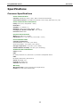
Specifications
Common Specifications
Serial Communication
Interface:
RS-485-2w: Data+, Data-, GND (5-contact terminal block)
Serial Line Protection:
15 kV ESD for all signals, Level 2 surge, EN 61000-4-5 (1 kV)
Serial Communication Parameters
Pa rit y:
None, Even, Odd (default = None)
Data Bits:
8
Stop Bits:
1, 2 (default = 1)
Baudrate:
1200 to 921.6 kbps (default = 9600)
Pull High/Low Resistor for RS-485:
1 kΩ, 150 kΩ
Protocols:
Modbus RTU
Physical Characteristics
W ir in g:
I/O cable max. 16 AWG
Dimensions:
27.8 x 124 x 84 mm (1.09 x 4.88 x 3.31 in)
Environmental Limits
Operating Temperature:
Standard Models:
-10 to 75°C (14 to 167°F)
Wide Temp. Models:
-40 to 85°C (-40 to 185°F)
Storage Temperature:
-40 to 85°C (-40 to 185°F)
Amb ient R e la t ive Hu mid ity:
5 to 95% (non-condensing)
Standards and Certifications
Safety:
UL 508
EMI:
EN 550
32, EN 61000-3-2, EN 61000-3-3, FCC Part 15 Subpart B Class A
EMS:
EN 55024, IEC 61000
-4, IEC 61000-6
Shock:
IEC 60068-2-27
Freefall:
IEC 60068-2-32
V ibra t io n:
IEC 60068-2-6
Warranty
Warranty Period:
5 years (excluding the ioLogik R1214)
Details:
See www.moxa.com/warranty

ioLogik R1200 Series Overview
1-4
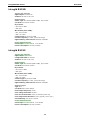
ioLogik R1210
Inputs and Outputs
D ig ita l In put s:
16 channels
Iso la t io n:
3K VDC or 2K Vrms
Digital Input
Sensor Type:
Wet Contact (NPN or PNP), Dry Contact
I/O Mode:
DI or Event Counter
Dry Contact:
• On: short to GND
• Off: open
Wet Contact (DI to
COM):
• On:
10 to 30 VDC
• Off: 0 to 3 VDC
Commo n Type:
8 points per COM
Counter Frequency:
2.5 kHz, power off storage
D ig ita l F ilter ing T ime I nte rva l:
Software selectable
Power Requirements
Power Input:
24 VDC nominal, 12 to 48 VDC
Power Consumption:
154 mA @ 24VDC
ioLogik R1212
Inputs and Outputs
D ig ita l In put s:
8 channels
Conf ig ura b le D IO s :
8 channels
Iso la t io n:
3K VDC or 2K Vrms
Digital Input
Sensor
Type: Wet Contact (NPN or PNP), Dry Contact
I/O Mode:
DI or Event Counter
Dry Contact:
• On: short to GND
• Off: open
Wet Contact (DI to
COM):
• On:
10 to 30 VDC
• Off: 0 to 3 VDC
Commo n Type:
8 points per COM
Counter Frequency:
2.5 kHz, power off storage
D ig ita l F ilter ing T ime I nte rva l:
Software selectable
Digital Output
Type:
Sink
I/O Mode:
DO or Pulse Output
Pulse Output Frequency:
5 kHz
Over
-voltage P rote c t io n: 45 VDC
Over
-current Protection: 2.6 A (4 channels @ 650 mA)
Over
-temperature Shutdown: 175°C (typical), 150°C (min.)
Current Rating:
200 mA per channel
Power Requirements
Power Input:
24 VDC nominal, 12 to 48 VDC
Power Consumption:
187 mA @ 24VDC

ioLogik R1200 Series Overview
1-5
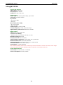
ioLogik R1214
Inputs and Outputs
D ig ita l In put s:
6 channels
Relay Outputs:
6 channels
Iso la t io n:
3K VDC or 2K Vrms
Digital Input
Sensor Type:
Wet Contact (NPN or PNP), Dry Contact
I/O Mode:
DI or Event Counter
Dry Contact:
• On: short to GND
• Off: open
Wet Contact (DI to
COM):
• On:
10 to 30 VDC
• Off: 0 to 3 VDC
Commo n Type:
6 points per COM
Counter Frequency:
2.5 kHz, power off storage
D ig ita l F ilter ing T ime I nte rva l:
Software selectable
Relay Output
Type:
Form A (N.O.) power relay
Contact Current Rating:
• Resistive
Load: 5 A @ 30 VDC, 250 VAC, 110 VAC
Breakdown Voltage:
500 VAC
Relay On/Off Time:
1500 ms (Max.)
Initial Insulation Resistance:
1000 M ohms (min.) @ 500 VDC
Mechanical Endurance:
5,000,000 operations
Ele c tr ica l E ndura n ce:
100,000 operations @ 5 A resistive load
Contact Resistance:
100 m ohms (max.)
Pulse Output:
0.3 Hz at rated load
Note: Ambient humidity must be non
-
condensing and remain between 5 and 95%. The relays of the ioLogik
R1214 may malfunction when operating
in high condensation environments below 0°C.
Power Requirements
Power Input:
24 VDC nominal, 12 to 48 VDC
Power Consumption:
207 mA @ 24VDC

ioLogik R1200 Series Overview
1-6
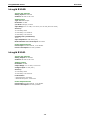
ioLogik R1240
Inputs and Outputs
Analog Inputs:
8 channels
Iso la t io n:
3K VDC or 2K Vrms
Analog Input
Type:
Differential input
R esolu t io n:
16 bits
I/O Mode:
Voltage / Current
Input Range:
0 to 10 VDC, 0 to 20 mA, 4 to 20 mA (burn-out mode)
Accuracy:
±0.1% FSR @ 25°C
±0.3% FSR @
-10 and 60°C
±0.5% FSR @
-40 and 75°C
Sampling Rate (a ll channe ls):
12 Hz
Input Impedance:
10M ohms (min.)
Built-in Resistor for Current Input:
120 ohms
Power Requirements
Power Input:
24 VDC nominal, 12 to 48 VDC
Power Consumption:
216 mA @ 24VDC
ioLogik R1241
Inputs and Outputs
Analog Outputs:
4 channels
Iso la t io n:
3K VDC or 2K Vrms
Analog Output
R esolu t io n:
12 bits
Output Range:
0 to 10 VDC, 4 to 20 mA
Voltage Output:
10 mA (max.)
Accuracy:
±0.1% FSR @ 25°C
±0.3% FSR @
-40 and 75°C
Load Resistor:
• Internal power: 400 ohms
• External 24V power: 1000 ohms
Power Requirements
Power Input:
24 VDC nominal, 12 to 48 VDC
Power Consumption:
343 mA @ 24VDC

ioLogik R1200 Series Overview
1-7
Physical Dimensions
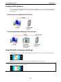
The dimensions of the ioLogik R1200 product are 27.8 x 124 x 84 mm. The connector for t he two RS-485
port s is a 5-pin 3.81 terminal block (2 RS-485 ports with 1 ground pin). The power connector is on the top
and the reset button is on the bottom of the product. There are also two dials for Board ID setup, and a 2-
pin DIP swi tch for “Initial/Run” mode and “Dual RS-485/Repeater” mode setup.
Hardware Reference
Panel Guide

ioLogik R1200 Series Overview
1-8
NOTE
The RESET button restarts the server and resets all settings to factory defaults. Use a pointed object such
as a straightened paper clip to hold down the reset button for 5 seconds. The factory defaults will
load once
the READY LED turns green again. You may then release the RESET button.
LED Indicators
LED State De scr ip t io n
Power (PW R) Amber Sys tem power is ON
OFF Sys tem power is OFF
Read (RDY) Green System is ready
Flashing Flashes every 1 sec when the Locate function is triggered
Flashing Flashes every 0.5 sec when the firmware is being upgraded
Flashing Flashing USB upgrade is triggered
OFF System is not ready.
Port 1 (P1) Green Serial connection enabled
Flashing Transmitting or receiving data
Port 2 (P2) Green Serial connection enabled
Flashing Transmitting or receiving data
Switch Settings
The R1200 series provides Dual/Rep and Run/Initial switch settings for setting the communication mode.
Dual (Default) Dual RS-485 mode
Rep Repeater mode
Run Use r defined communication parameters
Initial (Default) Initial RS-485 communication parameters
DI Circuit Diagram

ioLogik R1200 Series Overview
1-9
DIO Circuit Diagram

ioLogik R1200 Series Overview
1-10
Relay Circuit Diagram
AI Circuit Diagram

2
2. Initial Setup
The following topics are covered in this chapter:
Hardware Installation
Connecting the Power
Grounding the ioLogik R1200
Connecting to Serial Interface
Mounting the ioLogik R1200
Connecting to Digital Sensors and Devices
RS-485 Networks
Modbus/RTU Devices
Dual RS-485 or Repeater Settings
Jumper Settings (DIO and AI)
Pull High/Low DIP Switch Settings for the RS-485 Port
Software Installation
ioSearch Installation
Initial Setup by USB
Restore Factory Default Settings

ioLogik R1200 Series Initial Setup
2-2
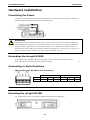
Hardware Installation
Connecting the Power
Connect the 12 to 48 VDC power line to the ioLogik R1200’s terminal block on the top panel. If power is
properly supplied, the Power LED will glow a solid amber color.
ATTENTION
Determine the maximum possible current for each power wire and common wire. Observe all electrical
codes dictating the maximum current allowable for
each wire size. If the current exceeds the maximum
rating, the wiring could overheat, causing serious damage to your equipment. For safety reasons, we
recommend an average cable size of 22 AWG. However, depending on the current load, you may want to
adjus
t your cable size (the maximum wire size for power connectors is 2 mm).
Grounding the ioLogik R1200
The ioLogik
R1200 is equipped with a grounding point on the terminal block located on the top
panel. Connect the ground pin if an earth ground is
available.
Connecting to Serial Interface
TB1 and TB2 (two RS-485 2-wire connectors)
TB1 (RS-485) TB2 (RS-485)
Pin 1 2 3 4 5 3
S igna l D1+ D1- GND D2+ D2- GND
NOTE
TB1 and TB2 share the same ground
.
Mounting the ioLogik R1200
The ioLogik R1200 can be used with both DIN rail and wall mounting applications.

ioLogik R1200 Series Initial Setup
2-3
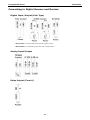
Connecting to Digital Sensors and Devices
Digital Input/Output (Sink Type)
A Dry Contact is a contact that works without a power source.
A Wet Contact is a contact that must work with a power source.
Analog Input/Output
Relay Output (Form A)

ioLogik R1200 Series Initial Setup
2-4
NOTE
A “load” in a circuit schematic is a component or portion of the circuit that consumes electric power. For the
diagrams shown in this document, “load” refe
rs to the devices or systems connected to the remote I/O unit.
RS-485 Networks
RS-485 permits a balanced transmission line to be shared in a party line or multi-drop configuration. As
many as 32 driver/receiver pairs can share a multi-drop connection on a single two-wire bus. The length of
the network is limited to 4,000 ft between the first node and the last node. You can use RS-485 in two-wire
or four-wire multi-drop network applications.
In an RS-485 four- wire network, one node must be a master node and all others slave nodes. The master
does not require tri-state output.
NOTE
The transmission line is terminated on both ends of the line but not at
drop points in the middle of the line.
Termination is only required with high data
rates or long wire runs.
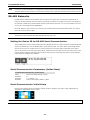
Setting the Device ID for RS-485 Serial Communication
The RS-485 port is used to communicate with other RS-485 devices or to link to another ioLogik RS-485 I/O
server. The RS-485 port can run Modbus/RTU or I/O command sets. The devi ce ID for each ioLogik R1200
device can be set to any number from 01 to 99 by turning the two rotary dials on the back of the device.
The x1 dial (shown on the left in the figure below) represents the ones place and the x10 dial (shown on the
right in the figure below) represents the tens place. Sett ings such as the baud rate, parity check, data bits,
and stop bit are configured by software.
Serial Communication Parameters (Initial State)
Communication Parameters (Initial mode)
Parity None, Even, Odd (default = None)
Data Bits 8
Stop Bits 1, 2 (default = 1)
Baudrate 1200 to 921.6 kbps (default = 9600)
Serial Communication Initial Setup
During your initial setup, set the swi t ch to “Initial” mode to configure your device, after configuration is
done flip the swit ch back t o “Run” mode.
NOTE
The
initial communication setting is: baudrate = 9600, n, 8, 1.

ioLogik R1200 Series Initial Setup
2-5
Modbus/RTU Devices
The RS-485 port runs Modbus/RTU and can connect to any Modbus device. You may use different methods
to connect different combinations of ioLogik R12000 servers and other Modbus devices. Some examples are
shown below:
Connecting One Modbus/RTU Device
Connecting Multiple Modbus/RTU Devices
Dual RS-485 or Repeater Settings
Dua l R S-485: Switching the dial to “Dual” will divide t he RS-485 port into two separate RS-485 ports for
users to run dual RS-485 lines.
Repeater: Switching the dial to “Rep” will set the ioLogik R1200 to act as a repeater.
NOTE
In
Repeater mode, when signals pass through one machine, the latency will increase by 1 byte wit h a
maximum
of 10 ms at 1200 bps baudrate.

ioLogik R1200 Series Initial Setup
2-6
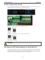
Jumper Settings (DIO and AI)
The models with DIO or AI channels require configuring the jumpers inside the cover. Remove the screw
located on the back panel and open the cover to configure the jumpers.
DIO mode configuration is shown to the right (default: DO Mode).
Analog mode configuration is shown to the right (default: Voltage Mode).
ATTENTION
Remove the screw on the back panel and open the cover to configure the jumpers.
Pull High/Low DIP Switch Settings for the RS-485 Port
In some critical environments, you may need to add termination resistors to prevent the reflection of serial
signals. When using termination resistors, it is important to set the pull high/low resistors correctly so that
the electrical signal is not corrupted. Since there is no resistor value that works for every environment, DIP
switches are used to set the pull high/low resistor valve for each RS-485 port.
Strona się ładuje...
Strona się ładuje...
Strona się ładuje...
Strona się ładuje...
Strona się ładuje...
Strona się ładuje...
Strona się ładuje...
Strona się ładuje...
Strona się ładuje...
Strona się ładuje...
Strona się ładuje...
Strona się ładuje...
Strona się ładuje...
Strona się ładuje...
Strona się ładuje...
Strona się ładuje...
Strona się ładuje...
Strona się ładuje...
Strona się ładuje...
Strona się ładuje...
Strona się ładuje...
Strona się ładuje...
Strona się ładuje...
Strona się ładuje...
Strona się ładuje...
Strona się ładuje...
Strona się ładuje...
Strona się ładuje...
Strona się ładuje...
Strona się ładuje...
Strona się ładuje...
Strona się ładuje...
Strona się ładuje...
Strona się ładuje...
Strona się ładuje...
Strona się ładuje...
Strona się ładuje...
Strona się ładuje...
Strona się ładuje...
Strona się ładuje...
Strona się ładuje...
Strona się ładuje...
Strona się ładuje...
Strona się ładuje...
Strona się ładuje...
Strona się ładuje...
Strona się ładuje...
Strona się ładuje...
Strona się ładuje...
Strona się ładuje...
Strona się ładuje...
Strona się ładuje...
Strona się ładuje...
Strona się ładuje...
Strona się ładuje...
Strona się ładuje...
Strona się ładuje...
Strona się ładuje...
Strona się ładuje...
Strona się ładuje...
Strona się ładuje...
Strona się ładuje...
Strona się ładuje...
-
 1
1
-
 2
2
-
 3
3
-
 4
4
-
 5
5
-
 6
6
-
 7
7
-
 8
8
-
 9
9
-
 10
10
-
 11
11
-
 12
12
-
 13
13
-
 14
14
-
 15
15
-
 16
16
-
 17
17
-
 18
18
-
 19
19
-
 20
20
-
 21
21
-
 22
22
-
 23
23
-
 24
24
-
 25
25
-
 26
26
-
 27
27
-
 28
28
-
 29
29
-
 30
30
-
 31
31
-
 32
32
-
 33
33
-
 34
34
-
 35
35
-
 36
36
-
 37
37
-
 38
38
-
 39
39
-
 40
40
-
 41
41
-
 42
42
-
 43
43
-
 44
44
-
 45
45
-
 46
46
-
 47
47
-
 48
48
-
 49
49
-
 50
50
-
 51
51
-
 52
52
-
 53
53
-
 54
54
-
 55
55
-
 56
56
-
 57
57
-
 58
58
-
 59
59
-
 60
60
-
 61
61
-
 62
62
-
 63
63
-
 64
64
-
 65
65
-
 66
66
-
 67
67
-
 68
68
-
 69
69
-
 70
70
-
 71
71
-
 72
72
-
 73
73
-
 74
74
-
 75
75
-
 76
76
-
 77
77
-
 78
78
-
 79
79
-
 80
80
-
 81
81
-
 82
82
-
 83
83


Moxa ioLogik R1200 Series Instrukcja obsługi
- Typ
- Instrukcja obsługi
w innych językach
Powiązane artykuły
Inne dokumenty
-
ICP I-87026PW Instrukcja obsługi
-
Sierra QuadraTherm 640i/780i Modbus Instrukcja obsługi
-
-
OUMAN MODBUS-100 Instrukcja obsługi
-
Omron S8VT-F12024E Skrócona instrukcja obsługi
-
Jandy AquaLink RS series Troubleshooting Manual
-
ABB ACS580-04 Quick Installation Manual
-
 Hach CD500 Instrukcja obsługi
-
-
