Classic Exhibits VK-2928 Setup Instructions
- Typ
- Setup Instructions

www.classicexhibits.com
866.652.2100
© 2015
WHEN DISASSEMBLING ALUMINUM EXTRUSION, TIGHTEN ALL
SETSCREWS AND LOCKS TO PREVENT LOSS DURING SHIPPING
Order #XXXXX -
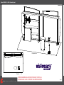
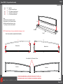
Perspective View
Plan View 20’
10’
VK-2928 - General Layout

www.classicexhibits.com
866.652.2100
© 2015
WHEN DISASSEMBLING ALUMINUM EXTRUSION, TIGHTEN ALL
SETSCREWS AND LOCKS TO PREVENT LOSS DURING SHIPPING
Order #XXXXX - General Information
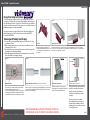
The Tool Typical Connection
Horizontal Inline Connection (remove only one setscrew)
Base Plate Connection Vertical Connection
(remove only two setscrews)
Most Visionary Designs exhibits can be
assembled with the supplied Hex Key Tool.
Occasionally, a flat head screwdriver may
be required.
Most horizontal extrusion connections have a patented expandable lock. This lock inserts into
the groove of an opposing extrusion. Tightening the lock with the Hex Key Tool expands the lock
and creates a strong positive connection.
Remove only (1) setscrew when disassembling. Replace setscrew in
extrusion after assembling it. Before packing, replace setscrew in
extrusion to avoid losing it.
Attach base plate to round or square
vertical extrusion using the bolt provided.
Be careful not to strip the threads.
When vertical extrusions are packed in
portable cases rather than crates or
tubs, they must broken down into
smaller sections which then require
assembly.
Remove only (2) setscrews when
disassembling. Replace setscrews in
extrusion after assembling it. Before
packing, replace setscrews in extrusion
to avoid losing them.
Using Your Setup Instructions
The Visionary Designs Setup Instructions are created specifically for your
configuration. They are laid out sequentially, including an exploded view of
the entire display, and then a logical series of detailed steps to assemble the
main structure and components. We encourage you to study the instructions
before attempting to assemble your exhibit.
Each page reminds you to tighten the setscrews after disassembling your
exhibit to prevent loss of the locks and setscrews (see below in RED).
This is VERY IMPORTANT.
Cleaning and Packing Your Display
1) Use care when cleaning aluminum extrusion or acrylic inserts. Use only
non-abrasive cleaners.
2) When cleaning laminate inserts or countertops, use mild cleansers and a
soft material such as cotton.
3) Keep all display components away from extreme heat and long exposure
to sunlight to avoid warping and fading.
4) Retain all packing material. It will make re-packing much easier and will
reduce the likelihood of shipping damage.
Typical Connection (cont’d)
Numbered Label
Each extrusion contains a numbered label which
corresponds with setup instructions.
The label is located within a groove of the extrusion
(when possible). With Visionary Designs the labels
contain Black numbers unless otherwise specified.
Detail C E liateDD liateDDetail B
Detail A
Setscrews

www.classicexhibits.com
Step 1
Page 1 of 6
866.652.2100
© 2015
WHEN DISASSEMBLING ALUMINUM EXTRUSION, TIGHTEN ALL
SETSCREWS AND LOCKS TO PREVENT LOSS DURING SHIPPING
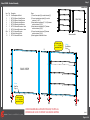
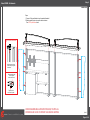
Order #XXXXX - Backwall Assembly
111a
1
6
7
5
4
6
8
8a
9
7
32
10
10
When assembled
FRONT VIEW
BACK VIEW
Item
1/1a
2
3
4
5
6
7
8/8a
9
10
Qty.
3/1
1
1
1
1
2
2
1/1
1
2
Description
Oval Baseplate with Notch
80” Q914 Square Vertical Extrusion
80” Q914 Square Vertical Extrusion
80” Q914 SquareVertical Extrusion
80” Q914 SquareVertical Extrusion
86” Z45 Horizontal Extrusion w/ velcro
86” Z45 Horizontal Extrusion w/ velcro
86” Z45 Horizontal Extrusion
86” Monitor Mounting Plate
20” Z45 Horizontal Extrusion
Steps:
1) Connect base plate [1a] to vertical extrusion [2].
2) Connect remaining base plates [1] to vertical
extrusions [3, 4, & 5].
3) Attach horiztonal extrusions [6, 7, 8, & 9] between
vertical extrusions [2] & [3].
4) Attach horizontal extrusions [6 & 7] between
vertical extrusions [4] & [5].
5) Connect horizontal extrusions [10] between
vertical extrusions [3] & [4].
6) Attach graphics to backside of frame.
Velcro:
Back/Bottom
Edge
Velcro:
Back/Top
Edge
Attach graphic
to velcro on back of
assembled frame
Attach graphic
to velcro on back of
assembled frame

www.classicexhibits.com
Step 2
Page 2 of 6
866.652.2100
© 2015
WHEN DISASSEMBLING ALUMINUM EXTRUSION, TIGHTEN ALL
SETSCREWS AND LOCKS TO PREVENT LOSS DURING SHIPPING
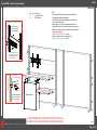
Order #XXXXX - Backwall Counter Assembly
8a
9
8
Assembled Kiosk
[17] Large Counter Top
Item
17
18
Qty.
1
1
Description
Large Counter Top
Small Counter
Steps:
1) Connect stand-off barrels to top of assembled kiosk and
set kisok against assembled backwall.
NOTE: Back outer corner of assembled kiosk will fit within
the notched base plate [1a].
2) Attach large counter top to top of assembled kiosk and
stand-off barrels as well as backwall horizontal extrusion [8a].
3) Attach small counter to side of assembled kiosk and backwall
horizontal extrusion [8].
See Counter to Kiosk Attachment detail.
4) Connect monitor mount to mounting plate [9].
See Monitor Mount Attachment detail.
[18] Small Counter Top
*
**
**
Counter to
Kiosk Attachment
Insert bolts through holes
in side of kiosk & counter.
Secure with wing nuts.
Wing Nut
Assembled Kiosk
Attach wall plate to
horizontal bar using
bolts and wing nuts
Hook monitor brackets over
top of wall plate, then secure
with safety bolts to bottom
of monitor brackets.
Monitor Mount Attachment
*

www.classicexhibits.com
Step 3
Page 3 of 6
866.652.2100
© 2015
WHEN DISASSEMBLING ALUMINUM EXTRUSION, TIGHTEN ALL
SETSCREWS AND LOCKS TO PREVENT LOSS DURING SHIPPING
Order #XXXXX - Ceiling and Header Assembly
Steps:
1) Attach header pieces together as shown.
2) Apply graphic to front of assembled header.
3)
Attach assembled header frame to ceiling
by locking to connectors where indicated.
Note: Frame should be assembled from Backside.
13
14
15
16
Backside View
Front View
Front View
Lock
Lock
Lock
Lock
Item
13/13
14/14
15/15
16/16
Qty
1/1
1/1
1/1
1/1
Description
90” Lower Horizontal Extrusion
8.75“ Tapered cut Vertical Extrusion
14” Tapered cut Vertical Extrusion
93” Curved Horizontal Extrusion
NOTE: Header frame must stay assembled when shipping in crate
Assembled Header Frame with Graphic at Front
Lock
Lock
Connector
Ceiling
Velcro Applied to Front Perimeter of Frame
13
14 15
16
Backside View
Lock
Lock
LockLock

www.classicexhibits.com
Step 4
Page 4 of 6
866.652.2100
© 2015
WHEN DISASSEMBLING ALUMINUM EXTRUSION, TIGHTEN ALL
SETSCREWS AND LOCKS TO PREVENT LOSS DURING SHIPPING
Order #XXXXX - Attachments
Steps:
1) Connect Ceiling and Header to top of assembled backwall.
2) Attach graphic wings to outer most vertical extrusions.
See A10 Clip Attachment detail.
When desired location
is found, tighten
set screw to secure.
Tighten knob to
secure shelf in place.
Slide connector on back
of A10 clamp into groove
of extrusion.
A10 Clamp Attachment
*
*
*
*
*
*
*

www.classicexhibits.com
Step 5
Page 5 of 6
866.652.2100
© 2015
WHEN DISASSEMBLING ALUMINUM EXTRUSION, TIGHTEN ALL
SETSCREWS AND LOCKS TO PREVENT LOSS DURING SHIPPING
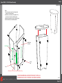
Order #XXXXX - LTK-1001 Pedestal Assembly
Steps:
1) Use screw caps to secure the front panel and
back panel to the side panels.
2) Slide floor into the bottom of the pedestal. The
floor will sit on pins set into the side panels.
3) Attach shelf supports with velcro to inside of panel.
4) Place counter top on assembled pedestal.
Screw
Cap
Back Panel
with Door
Floor
Shelf Supports Shelf
*
*
Remove pins for floor from side panels when packing
Counter Top

www.classicexhibits.com
Step 6
Page 6 of 6
866.652.2100
© 2015
WHEN DISASSEMBLING ALUMINUM EXTRUSION, TIGHTEN ALL
SETSCREWS AND LOCKS TO PREVENT LOSS DURING SHIPPING
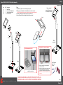
Order #XXXXX - MOD-1333 iPad Kiosk Assembly
22
Clamshell
When
assembled
Rotate clamshell
to turn iPad from portrait
to landscape orientation
19
20
21
Hex
Nuts
Steps:
1) Attach base [19] to curved vertical [20] using bolts.
2) Slide square plate [21] into vertical [20] and secure with set screw.
NOTE: Square plate [3] must rotate to left and right before installing clamshell
3) Attach clamshell [22] to square plate [21] using hex nuts.
4) Insert iPad and feed wire through holes as shown in detail.
Clamshell
Set
Screw
Stand Tools Required:
1) Hex Tool
2) Pliers
Wire
Access
iPad
Lock
Lock
Foam Lining
Removed
Home Button Shield
Optional Cover for Home Button
Wire Management for iPad
1) Remove foam lining from inside bottom of
clamshell as shown.
2) Attach Home Button Shield with double-sided
tape to inside of clamshell, keeping top of
shield flush with clamshell opening as shown.
NOTE: This is a permanent fix and can’t be easily
removed.
Feed iPad charging cord through holes from top
to bottom of post as shown.
TOP
Item
19
20
21
22
Qty.
1
1
1
1
Description
Base Plate
Formed Vertical Extrusion
Square Mounting Plate
iPad Clamshell
-
 1
1
-
 2
2
-
 3
3
-
 4
4
-
 5
5
-
 6
6
-
 7
7
-
 8
8


Classic Exhibits VK-2928 Setup Instructions
- Typ
- Setup Instructions
w innych językach
- English: Classic Exhibits VK-2928
Powiązane artykuły
-
Classic Exhibits VK-2916 Setup Instructions
-
-
-
-
-
-
-
-
-