
www.classicexhibits.com
Step 1
Page 1 of 5
866.652.2100
© 2013
WHEN DISASSEMBLING ALUMINUM EXTRUSION, TIGHTEN ALL
SETSCREWS AND LOCKS TO PREVENT LOSS DURING SHIPPING
Order #XXXXX -
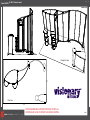
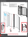
VK-2924 - General Layout
20’
Plan View
Perspective View
Perspective View
10’

www.classicexhibits.com
Step 2
Page 2 of 5
866.652.2100
© 2013
WHEN DISASSEMBLING ALUMINUM EXTRUSION, TIGHTEN ALL
SETSCREWS AND LOCKS TO PREVENT LOSS DURING SHIPPING
Order #XXXXX -
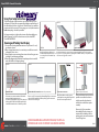
General Information
The Tool Typical Connection
Horizontal Inline Connection (remove only one setscrew)
Base Plate Connection Vertical Connection
(remove only two setscrews)
Most Visionary Designs exhibits can be
assembled with the supplied Hex Key Tool.
Occasionally, a flat head screwdriver may
be required.
Most horizontal extrusion connections have a patented expandable lock. This lock inserts into
the groove of an opposing extrusion. Tightening the lock with the Hex Key Tool expands the lock
and creates a strong positive connection.
Remove only (1) setscrew when disassembling. Replace setscrew in
extrusion after assembling it. Before packing, replace setscrew in
extrusion to avoid losing it.
Attach base plate to round or square
vertical extrusion using the bolt provided.
Be careful not to strip the threads.
When vertical extrusions are packed in
portable cases rather than crates or
tubs, they must broken down into
smaller sections which then require
assembly.
Remove only (2) setscrews when
disassembling. Replace setscrews in
extrusion after assembling it. Before
packing, replace setscrews in extrusion
to avoid losing them.
Using Your Setup Instructions
The Visionary Designs Setup Instructions are created specifically for your
configuration. They are laid out sequentially, including an exploded view of
the entire display, and then a logical series of detailed steps to assemble the
main structure and components. We encourage you to study the instructions
before attempting to assemble your exhibit.
Each page reminds you to tighten the setscrews after disassembling your
exhibit to prevent loss of the locks and setscrews (see below in RED).
This is VERY IMPORTANT.
Cleaning and Packing Your Display
1) Use care when cleaning aluminum extrusion or acrylic inserts. Use only
non-abrasive cleaners.
2) When cleaning laminate inserts or countertops, use mild cleansers and a
soft material such as cotton.
3) Keep all display components away from extreme heat and long exposure
to sunlight to avoid warping and fading.
4) Retain all packing material. It will make re-packing much easier and will
reduce the likelihood of shipping damage.
Typical Connection (cont’d)
Numbered Label
Each extrusion contains a numbered label which
corresponds with setup instructions.
The label is located within a groove of the extrusion
(when possible). With Visionary Designs the labels
contain Black numbers unless otherwise specified.
Detail C E liateDD liateDDetail B
Detail A
Setscrews

www.classicexhibits.com
Step 1
Page 1 of 5
866.652.2100
© 2013
WHEN DISASSEMBLING ALUMINUM EXTRUSION, TIGHTEN ALL
SETSCREWS AND LOCKS TO PREVENT LOSS DURING SHIPPING
Order #XXXXX -
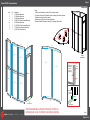
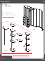
Room Assembly
1
1
4a
4a
2
3
4
4
4
4
4
4
4
4
Infill
Infill
Infill
Infill
Infill
Infill
Infill
Infill
Infill
4
Door
5
6
6
7
When
assembled
Plan View
2
3
Item Qty Description
1 1 96” S44 Vertical Extrusion
2 1 96” S44 Vertical Extrusion
3 1 96” S44 Vertical Extrusion
4 9 22.8062” Z45 Curved Horizontal Extrusion
4a 1 96” S44 Vertical Extrusion
5 2 27.4515” Z45 Curved Horizontal Extrusion
6 2 77.28” Z45 Curved Horizontal Extrusion
7 1 92.418” Z45 Vertical Extrusion
Steps:
1) Attach door threshold to verticals [2 & 3] as shown in detail.
2) Connect horizontals [4,5] between verticals, inserting infills where indicated
.
3) Attach door to hinges as shown in detail.
4) Attach vertical [7] between horizontals [6] as shown.
5) Attach horizontals [6] between verticals [1 & 3] inserting infills as shown.
Door Attachment
Pin
Slide pin into
hinge attached
to vertical.
Slide door
hinge atop pin.
Door
Hinge
Hinge
Door Threshold
Door Threshold
Tighten setscrew
to secure
Slide Connector
into Groove
of Extrusion
5

www.classicexhibits.com
Step 2
Page 2 of 5
866.652.2100
© 2013
WHEN DISASSEMBLING ALUMINUM EXTRUSION, TIGHTEN ALL
SETSCREWS AND LOCKS TO PREVENT LOSS DURING SHIPPING
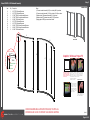
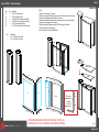
Order #XXXXX - SEG Backwall Assembly
8
9
10
11
12
13
14
15
16
17 17
When
assembled
Item Qty Description
8 1 95.75” TSP49 Vertical Extrusion
9 1 95.75” TSP49 Vertical Extrusion
10 1 67.692” TSP49 Curved Horizontal Extrusion
11 1 67.692” TSP49 Curved Horizontal Extrusion
12 1 92.168” Z45 Vertical Extrusion
13 1 95.75” TSP49 Vertical Extrusion
14 1 95.75” TSP49 Vertical Extrusion
15 1 96.5341” TSP49 Curved Horizontal Extrusion
16 1 96.5341” TSP49 Curved Horizontal Extrusion
17 2 92.168” Z45 Vertical Extrusion
Steps:
1) Connect curved horizontals [10,11] to verticals (8 & 9) as shown.
2)
Connect curved horizontals [15,16] to verticals (13 & 14) as shown
.
3) Attach vertical [12] between horizontals [10,11] as shown.
4) Attach verticals [17] between horizontals [15 & 16] as shown.
5) Apply graphic to SEG groove as shown in detail.
Graphic Removal
To remove the graphic from
the frame, locate the fabric
pull tab. Gently pull up on the
tab to remove the fabric.
Step 1
Insert corner A. Turn edge of
graphic so silicon welt is
perpendicular to face of
graphic. Insert narrow side
of welt with fabric to outside
into the channel. Repeat for
other side of this corner.
Step 2
Repeat Step 1 for opposite
corner C, then insert corner
B, followed by corner D, to
complete the installation of
the corners.
Step 3
Once all corners are inserted,
press one silicon edge into
channel from corners and
work toward the center.
Make sure welt is fully inserted
into channel. Continue until
all sides are done. Smooth
out edges of graphic.
Graphic: To Ensure Proper Fit
It is important to first insert
graphic into each alternate
corner then to the sides of
the frame. If this is not done,
graphic will not fit into the
frame correctly.
Corner A
Corner D
Corner B
Corner C
TSP49
Lock
Tighten setscrew
to secure
extrusions
TSV1 Lock Detail

www.classicexhibits.com
Step 3
Page 3 of 5
866.652.2100
© 2013
WHEN DISASSEMBLING ALUMINUM EXTRUSION, TIGHTEN ALL
SETSCREWS AND LOCKS TO PREVENT LOSS DURING SHIPPING
Order #XXXXX - Backwall Attachment
18
18
19
19
20
21
When
assembled
Item Qty Description
18 2 Base Plates
19 1 95.75” S44 Vertical Extrusion
20 1 95.75” S44 Vertical Extrusion
21 1 82.7636” Z45 Curved Horizontal Extrusion
Steps:
1) Connect verticals [19,20] to base plates with screws as shown.
2)
Connect vertical [19] between hroziontals [9 & 13] as shown
.
3) Attach vertical [20] to vertical [14] as shown.
4) Attach curved horizontal [21] between vertical [2 & 19] as shown.
5) Attach pamphlet trays to backwall where desired as shown in detail.
6) Attach graphic sign to backwall with screw caps as shown in detail.
Attach connector piece to tray
as shown. Then connect
assembled pamphlet
tray to vertical extrusion.
Adjustable Pamphlet Tray Attachment
Tighten Lock
to Secure
Graphic
Screw
Cap
V20
Graphic Sign Attachment
Slide V20 connector into groove
of extrusion, then secure graphic
to connector using screw cap.
Graphic
Sign

www.classicexhibits.com
Step 4
Page 4 of 5
866.652.2100
© 2013
WHEN DISASSEMBLING ALUMINUM EXTRUSION, TIGHTEN ALL
SETSCREWS AND LOCKS TO PREVENT LOSS DURING SHIPPING
Order #XXXXX - Shelving Attachment
22
23
23
Base Plate
Shelf Pin Location
Shelf
Shelf Shelf
Counter
Shelf
When
assembled
When
assembled
Item Qty Description
22 2 39.75” S44 Vertical Extrusion
23 4 19” Z45 Curved Horizontal Extrusion
Steps:
1) Attach curved horizontals [23] to verticals [22] as shown.
2)
Attach verticals [22] to bases using screws as shown
.
3) Attach curved horizontals [23] to backwall verticals [1 & 4a] and [2 & 4a].
4) Place shelves on shelf pins between verticals and wall as shown.
5) Place countertop on top of assembled shelving unit as shown.
*
*
*
*
*
*
*
*
*
*
*

www.classicexhibits.com
Step 5
Page 5 of 5
866.652.2100
© 2013
WHEN DISASSEMBLING ALUMINUM EXTRUSION, TIGHTEN ALL
SETSCREWS AND LOCKS TO PREVENT LOSS DURING SHIPPING
Order #XXXXX - Pedestal Assembly
24 25
26 28
26
1
2
Infill
Infill Infill
28
27
29
27
Door
Shelf
Counter Top
Counter
Item Qty Description
24 1 38” S44 Vertical Extrusion
25 1 38” S44 Vertical Extrusion
26 2 41.2385” Z45 Curved Horizontal Extrusion
27 2 41.2385” Z45 Curved Horizontal Extrusion
28 2 16.35” Z45 Horizontal Extrusion
29 1 34.41” Z45 Vertical Extrusion w/Door hinges
Item Description
1 5.75”r x 42“h Half Curve Panel
2 5.75”r x 42“h Half Curve Panel
Steps:
1) Attach curved panels [1,2] together.
2)
Attach horizontals [26] between panels and vertical [24], inserting infills as shown.
3) Attach vertical [29] between horizontals [27] as shown.
4) Attach horizontals [27] between panels and vertical [25], inserting infill as shown.
5) Hang door from hinges as shown in detail.
6) Attach horizontals [28] between verticals [24 & 25] placing infill as shown.
7) Place internal shelf on shelf supports
8) Set counter tops on top of assembled base.
Door
Hinge
Hinge
Door Attachment
Slide pin into
hinge attached
to vertical.
Slide door
hinge atop pin.

www.classicexhibits.com
866.652.2100
© 2013
WHEN DISASSEMBLING ALUMINUM EXTRUSION, TIGHTEN ALL
SETSCREWS AND LOCKS TO PREVENT LOSS DURING SHIPPING
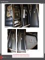
Order #XXXXX - Crate Packing
Level 1 Level 2 Level 3 Level 4
Level 5
Door
4 (x9)
23 (x4)
29 10 11
Bases
Infills
Infills
25
24
28 28
22 (x2)
Graphic Sign
26 (x2)
27 (x2)
Half Round Panel - 1
Half Round Panel - 2
Shelves
Shelves
Shelves
Counter
Counter
Counter
Counter
Level 6
Level 7
Setup Hardware
Literature Racks
Lights
Door
21
119
4a
4a
20
6
(x2)
89
13
14
3
2
15
16
7,12,17,17
-
 1
1
-
 2
2
-
 3
3
-
 4
4
-
 5
5
-
 6
6
-
 7
7
-
 8
8


Classic Exhibits visionary DESIGNS VK-2924 Instrukcja obsługi
- Typ
- Instrukcja obsługi
- Niniejsza instrukcja jest również odpowiednia dla
w innych językach
Powiązane artykuły
-
Classic Exhibits VK-2900 Setup Instructions
-
-
-
-
-
-
-
-
-