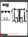
Classic Exhibits VK-2900 Setup Instructions
- Typ
- Setup Instructions

www.classicexhibits.com
Step 1
866.652.2100
© 2012
WHEN DISASSEMBLING ALUMINUM EXTRUSION, TIGHTEN ALL
SETSCREWS AND LOCKS TO PREVENT LOSS DURING SHIPPING
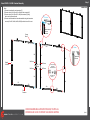
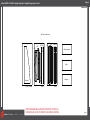
Order# XXXXX - VK-2900 - General Layout
20’
10’
Plan View

www.classicexhibits.com
Step 2
866.652.2100
© 2012
WHEN DISASSEMBLING ALUMINUM EXTRUSION, TIGHTEN ALL
SETSCREWS AND LOCKS TO PREVENT LOSS DURING SHIPPING
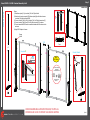
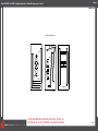
Order# XXXXX - VK-2900 - General Information
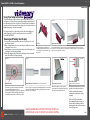
The Tool Typical Connection
Horizontal Inline Connection (remove only one setscrew)
Base Plate Connection Vertical Connection
(remove only two setscrews)
Most Visionary Designs exhibits can be
assembled with the supplied Hex Key Tool.
Occasionally, a flat head screwdriver may
be required.
Most horizontal extrusion connections have a patented expandable lock. This lock inserts into
the groove of an opposing extrusion. Tightening the lock with the Hex Key Tool expands the lock
and creates a strong positive connection.
Remove only (1) setscrew when disassembling. Replace setscrew in
extrusion after assembling it. Before packing, replace setscrew in
extrusion to avoid losing it.
Attach base plate to round or square
vertical extrusion using the bolt provided.
Be careful not to strip the threads.
When vertical extrusions are packed in
portable cases rather than crates or
tubs, they must broken down into
smaller sections which then require
assembly.
Remove only (2) setscrews when
disassembling. Replace setscrews in
extrusion after assembling it. Before
packing, replace setscrews in extrusion
to avoid losing them.
Using Your Setup Instructions
The Visionary Designs Setup Instructions are created specifically for your
configuration. They are laid out sequentially, including an exploded view of
the entire display, and then a logical series of detailed steps to assemble the
main structure and components. We encourage you to study the instructions
before attempting to assemble your exhibit.
Each page reminds you to tighten the setscrews after disassembling your
exhibit to prevent loss of the locks and setscrews (see below in RED).
This is VERY IMPORTANT.
Cleaning and Packing Your Display
1) Use care when cleaning aluminum extrusion or acrylic inserts. Use only
non-abrasive cleaners.
2) When cleaning laminate inserts or countertops, use mild cleansers and a
soft material such as cotton.
3) Keep all display components away from extreme heat and long exposure
to sunlight to avoid warping and fading.
4) Retain all packing material. It will make re-packing much easier and will
reduce the likelihood of shipping damage.
Typical Connection (cont’d)
Numbered Label
Each extrusion contains a numbered label which
corresponds with setup instructions.
The label is located within a groove of the extrusion
(when possible). With Visionary Designs the labels
contain Black numbers unless otherwise specified.
Detail C E liateDD liateDDetail B
Detail A
Setscrews

www.classicexhibits.com
Step 3
866.652.2100
© 2012
WHEN DISASSEMBLING ALUMINUM EXTRUSION, TIGHTEN ALL
SETSCREWS AND LOCKS TO PREVENT LOSS DURING SHIPPING
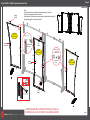
Order# XXXXX - VK-2900 - SEG Graphic Installation
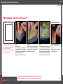
Graphic Removal
SEG Graphic: To Ensure Proper Fit
Corner A
Corner D
Corner B
Corner C
It is important to first insert graphic
into each alternater corner then to
the sides of the frame.
If this is not done, graphic will not fit
into the frame correctly.
Step 1
Insert corner A.
Turn edge of graphic so silicon welt
is perpendicular to face of graphic.
Insert narrow side of welt with fabric
to outside into the channel.
Repeat for other side of this corner.
Step 2
Repeat Step 1 for opposite corner
C, then insert corner B, followed by
corner corner D, to complete the
installation of the corners.
Step 3
Once all corners are inserted, press
one silicon edge into channel from
corners and work toward the center.
Make sure welt is fully inserted into
channel. Continue until all sides are
done. Smooth out edges of graphic.
To remove the graphic from
the frame, locate the fabric
pull tab.
Gently pull up on the tab to
remove the fabric.

www.classicexhibits.com
Step 4
866.652.2100
© 2012
WHEN DISASSEMBLING ALUMINUM EXTRUSION, TIGHTEN ALL
SETSCREWS AND LOCKS TO PREVENT LOSS DURING SHIPPING
Order# XXXXX - VK-2900 - SEG Graphic Installation
Item
13a/13b
14c/14d
15c/15d
16a/16b
17a/17b
18a/18b
19a/19b
20a/20b
A
B
C
Qty.
1/1
1/1
1/1
1/1
1/1
1/1
1/1
1/1
2
2
4
Description
41.5” TSP46 Vertical Extrusion
41.5” TSP46 Vertical Extrusion
41.5” TSP46/S44 Vertical Extrusion
41.5” TSP46 Vertical Extrusion
35” TSP46 Horizontal Extrusion
35” TSP46 Horizontal Extrusion
35” TSP46 Horizontal Extrusion
35” TSP46 Horizontal Extrusion
Straight Connector w/ Knobs
Straight Connector w/ Set Screws
Curved Connector w/ Knobs
Page 1
Backwall: SEG Frames
Item
1/1a
12a/12b
14a/14b
15a/15b
21
25a/25b
A
Item
1
2
2a
3
4
5
6
7
7a
8
9
10
11
22a/22b
23a/23b
24
A
B
D
E
Qty.
2/2
2/2
1/1
1/1
2
2/2
4
Qty.
2
1
1
1
1
1
1
1
1
1
1
1
1
1/1
1/1
4
6
2
2
2
Description
Base Plate
41.5” S44 Vertical Extrusion
41.5” S44 Vertical Extrusion
41.5” S44 Vertical Extrusion
6” S40 Angled Extrusion
Counter Top Supports
Straight Connector w/ Knobs
Description
Base Plate
TSP46 Lower Left Corner
16” TSP46 Horizontal Extrusion
TSP46 Upper Left Corner
19” TSP46 Horizontal Extrusion
36” TSP46 Vertical Extrusion
36” TSP46 Vertical Extrusion
TSP46 Lower Right Corner
16” TSP46 Horizontal Extrusion
TSP46 Upper Right Corner
19” TSP46 Horizontal Extrusion
36” TSP46 Vertical Extrusion
36” TSP46 Vertical Extrusion
TSP46 Front Left Lower/Upper Corners
TSP46 Front Right Lower/Upper Corners
6” S40 Horizontal Extrusion
Straight Connector w/ Knobs
Straight Connector w/ Set Screws
Curved Connector w/ Knobs
Curved Connector w/ Knobs
Item
26
27
28
29
30
31
32/33
34
35-37
Qty.
1
1
1
1
2
2
1/1
2
1/1/2
Description
38” Curved Vertical Extrusion
38” Vertical Extrusion
38” Vertical Extrusion
38” Curved Vertical Extrusion
11” Horizontal Extrusion w/ Lip
23” Horizontal Extrusion w/ Lip
14.567” Horizontal Extrusion
23” Horizontal Extrusion
Door Extrusions
Page 2
Backwall: Center Section
Page 3
Backwall: Side & Front Sections
Page 6
Pedestals (Qty. 2)

www.classicexhibits.com
Step 1
866.652.2100
© 2012
WHEN DISASSEMBLING ALUMINUM EXTRUSION, TIGHTEN ALL
SETSCREWS AND LOCKS TO PREVENT LOSS DURING SHIPPING
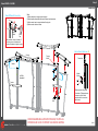
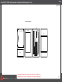
Order# XXXXX - VK-2900 - Backwall Assembly
Steps:
1) Connect horizontals with curved connectors [C].
2) Connect verticals [13a,13b] and [16a,16b] with knob connectors [A].
3) Connect verticals [14c,14d] and [15c,15d] with connectors [B] using
the hex tool to tighten set screws.
4) Connect vertical assemblies to horizontal assemblies using knob connectors
at corners [13a/17a,13b/18a,16a/19b,16b,20b] and the hex tool for the rest.
Tighten knob
to secure
Corner
and tighten knob
to secure
Slide connecting
bar between
verticals/horizontals
*
13a
13b
18a
18b
17a 17b
14c
14d
15c
15d
20a
20b
19a
19b
16a
16b
C
C
C
C
A
A
*
*
*
*
Curved
Connector
TSP46
Lock
Tighten setscrew
to secure
extrusions
No Knobs
*
*
*
*
*
Set Screw Set Screw
Set Screw Set Screw
No
Knobs
Straight
Connector BB
Canopy
Mount

www.classicexhibits.com
Step 2
866.652.2100
© 2012
WHEN DISASSEMBLING ALUMINUM EXTRUSION, TIGHTEN ALL
SETSCREWS AND LOCKS TO PREVENT LOSS DURING SHIPPING
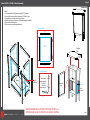
Order# XXXXX - VK-2900 - Backwall Assembly Cont’d
Steps:
1) Attach base plates [1,1a] to verticals [12a,14a,15a] with bolts.
2) Attach vertical counter supports [25a] to base plates [1a] with bolts and secure
to verticals [12a] with horizontals [25b].
3) Connect verticals [12b,14b,15b] to verticals [12a,14a,15a] with connectors [A].
4) Connect verticals [14a/14b] and [15a/15b] with horizontals [21] as shown.
5) Connect assembled SEG frames to assembled stands with bolts and cam locks
as shown.
6) Apply SEG Graphics to frames.
Top View
Cam Lock
Tighten screw to clamp cam lock
into groove of vertical extrusion.
Cam Lock*
and tighten knob
to secure
Slide connecting
bar between
verticals/horizontals
*
14b 15b
21
Top View
Front
Counter Stands
25b
25a
12a
1a
A
Stand Assembly
A
A
A
A
12a
12b
Canopy
Mount
12a
12b
14a
14b
15a
15b
*
21
21
1a
1a
11
*
*
*
*
*
*
**
15b
*
Apply
SEG Graphic
Flange

www.classicexhibits.com
Step 3
866.652.2100
© 2012
WHEN DISASSEMBLING ALUMINUM EXTRUSION, TIGHTEN ALL
SETSCREWS AND LOCKS TO PREVENT LOSS DURING SHIPPING
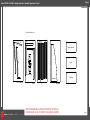
Order# XXXXX - VK-2900
Steps:
1) Assemble side frames as indicated, attaching base plates [1] with bolts.
2) Attach side frames with cam locks as shown.
3) Assemble front SEG frame as shown and attach to backwall with horizontals [24].
4) Apply SEG graphics to side and front frames.
2
3
4
5
6
1
7
8
9
10
11
1
22a
22b
23a
23b
24
24
24
24
A
A
A
A
D
D
E
E
and tighten knob
to secure
Slide connecting
bar between
verticals/horizontals
B
B
Curved
Connector
Curved
Connector
Canopy
Mount
Tighten knob
to secure
Corner
*
*
*
*
*
No
Knobs
No
Knobs
Top View
Cam Lock
Tighten screw to clamp cam lock
into groove of vertical extrusion.
Cam Lock*
*
*
*
*
Apply
SEG Graphic
Apply
SEG Graphic
Apply
SEG Graphic
A
A
2a
7a
- Backwall Assembly Cont’d

www.classicexhibits.com
Step 4
866.652.2100
© 2012
WHEN DISASSEMBLING ALUMINUM EXTRUSION, TIGHTEN ALL
SETSCREWS AND LOCKS TO PREVENT LOSS DURING SHIPPING
Order# XXXXX - VK-2900
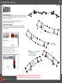
Connections are made by holding the button
down and sliding the red tube into opposing
tube until the connection is made. To disassemble
push button and pull or twist extrusions apart.
Push-Button
Push-Button
66
6
6
Numbered Label
Using Your Setup Instructions
The Aero Overhead Sign Setup Instructions are created specically for your conguration. They include an
exploded view of the frame which is sequentially numbered. We encourage you to study the instructions
before attempting to assemble your exhibit.
Connections are kept very simple: no tools. Everything assembles with push-button
connectors and pre-connected horizontal sections.
Cleaning and Packing Your Display
1) Use care when cleaning aluminum extrusion or acrylic inserts. Use only non-abrasive cleaners.
2) Retain all packing material. It will make re-packing much easier and will reduce the likelihood
of shipping damage.
Release
Button
Rotate posts inward
for packing & shipping
Small
Frames
Large
Frames
Left
Right
A
B
C
D
Release
Button
Release
Button
Steps:
1) Assemble Large Frames by attaching
parts in Alphabetical order.
2) Apply pillowcase graphics.
Left
Right
Release
Button
E
F
G
H
I
J
K
L
- Canopy Assembly

www.classicexhibits.com
Step 5
866.652.2100
© 2012
WHEN DISASSEMBLING ALUMINUM EXTRUSION, TIGHTEN ALL
SETSCREWS AND LOCKS TO PREVENT LOSS DURING SHIPPING
Order# XXXXX - VK-2900
Wing
Nuts
Header
Counter
Top
Canopy
Left Side
Assembled
Steps:
1) Attach canopies to canopy mounts as shown.
2) Attach headers to backwall with stand-off barrels and screw caps.
3) Attach counter tops to support stands with wing nuts.
4) Attach monitor mount as shown.
Stand-Off
Barrel
Slide connector on back of stand-off
barrel into groove of extrusion and
turn barrel clockwise to tighten in place.
Stand-Off Barrel & Screw Cap
Screw
Cap
Canopy
Mount
Monitor Mount Attachment
Slide connectors into groove
of extrusion. Tighten setscrews
to secure in place. Attach
monitor mount to connectors
with screws.
Connectors
Monitor
Mount
*
*
*

www.classicexhibits.com
Step 6
866.652.2100
© 2012
WHEN DISASSEMBLING ALUMINUM EXTRUSION, TIGHTEN ALL
SETSCREWS AND LOCKS TO PREVENT LOSS DURING SHIPPING
Order# XXXXX - VK-2900
Assembled
Door
Door
Hinge
Hinge
Door Attachment
Slide pin into
hinge attached
to vertical.
Slide door
hinge atop pin.
26
27
28
29
30
30
31
31
32
33
34
34
Bottom
35 36
37
37
HingeHinge
Door Assembly
Infill
Infill
Infill
Counter
Top
Infill
Lip for
Bottom
Setups:
1) Connect verticals [26-29] with horizontals [30,31] as shown.
2) Insert infills as shown and lock horizontals [32,33,34] in place.
3) Assemble door as shown and hang from hinges.
4) Attach shelf supports to velcro on infills inside assembled pedestal.
5) Place shelf on shelf supports.
6) Place counter top on assembled pedestal.
Shelf
Shelf
Support
Velcro
- Pedestal Assembly

www.classicexhibits.com
Step 1
866.652.2100
© 2012
WHEN DISASSEMBLING ALUMINUM EXTRUSION, TIGHTEN ALL
SETSCREWS AND LOCKS TO PREVENT LOSS DURING SHIPPING
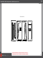
Order# XXXXX - VK-2900 - Packing Instruction - Backwall Components - Case 1
Top View of each Level
Slip SheetLevel 2
#7
#6
Level 1 (Bottom)
#17
#18
#2 #3
Level 3
Monitor Mounts
Lights
Graphics
#9
#10
Base plates
Headers
#4 #5

www.classicexhibits.com
Step 2
866.652.2100
© 2012
WHEN DISASSEMBLING ALUMINUM EXTRUSION, TIGHTEN ALL
SETSCREWS AND LOCKS TO PREVENT LOSS DURING SHIPPING
Order# XXXXX - VK-2900 - Packing Instruction - Backwall Components - Case 2
Top View of each Level
Level 1 (Bottom)
#42
#41
#45/46
#43
#44
Level 2 Level 3 Slip Sheet
#13 #14
#15
#16 #20
#19
2x Canopy

www.classicexhibits.com
Step 3
866.652.2100
© 2012
WHEN DISASSEMBLING ALUMINUM EXTRUSION, TIGHTEN ALL
SETSCREWS AND LOCKS TO PREVENT LOSS DURING SHIPPING
Order# XXXXX - VK-2900 - Packing Instruction - Backwall Components - Case 3
Top View of each Level
Level 1 (Bottom)
Setup Hardware
Lights
Graphics
Level 2
#32
#33
#28
#29
#31
#30
Headers
Level 3
#22 #23 #26
#27
#24 #25

www.classicexhibits.com
Step 4
866.652.2100
© 2012
WHEN DISASSEMBLING ALUMINUM EXTRUSION, TIGHTEN ALL
SETSCREWS AND LOCKS TO PREVENT LOSS DURING SHIPPING
Order# XXXXX - VK-2900 - Packing Instruction - Backwall Components - Case 4
Top View of each Level
Level 1 (Bottom)
#34
#35
#21
Level 2
Base plates
#37
#36
#39
#38
Slip Sheet
2x Canopy

www.classicexhibits.com
Step 5
866.652.2100
© 2012
WHEN DISASSEMBLING ALUMINUM EXTRUSION, TIGHTEN ALL
SETSCREWS AND LOCKS TO PREVENT LOSS DURING SHIPPING
Order# XXXXX - VK-2900
Top View of each Level
Level 1 (Bottom) Level 2 Level 3
Counter Top
Shelf
Infills #52
#51
#55/57
#59/60
#58
#54/56
#50/#53
Door
- Packing Instruction - Modul System Pedestal Components - Case 5

www.classicexhibits.com
Step 6
866.652.2100
© 2012
WHEN DISASSEMBLING ALUMINUM EXTRUSION, TIGHTEN ALL
SETSCREWS AND LOCKS TO PREVENT LOSS DURING SHIPPING
Order# XXXXX - VK-2900
Top View of each Level
Level 1 (Bottom) Level 2 Level 3
Counter Top
Shelf
Infills #52
#51
#55/57
#59/60
#58
#54/56
#50/#53
Door
- Packing Instruction - Modul System Pedestal Components - Case 6
-
 1
1
-
 2
2
-
 3
3
-
 4
4
-
 5
5
-
 6
6
-
 7
7
-
 8
8
-
 9
9
-
 10
10
-
 11
11
-
 12
12
-
 13
13
-
 14
14
-
 15
15
-
 16
16


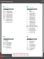
Classic Exhibits VK-2900 Setup Instructions
- Typ
- Setup Instructions
w innych językach
- English: Classic Exhibits VK-2900
Powiązane artykuły
-
Classic Exhibits VK-1122 Setup Instructions
-
-
-
-
-
-
-
-
-