Classic Exhibits TF-523 Setup Instructions
- Typ
- Setup Instructions

© 2017
www.classicexhibits.com
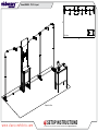
Order #XXXXX - TF-523 - Layout
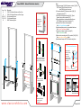
SETUP INSTRUCTIONS
If you would like to tell us about your experience with your setup instructions please email us at [email protected]
Plan View
Perspective View
10’
20’

© 2017
www.classicexhibits.com
Order #XXXXX -
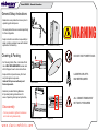
DO NOT USE POWER TOOLS
ALL CONNECTIONS MUST
BE TIGHTLY SECURED
Part Identification - Numbering
Spline Connection Base Plate & Extrusion Connection
General Setup Instructions
- Read entire setup instruction manual prior to
unpacking parts and pieces.
- The setup instructions are created specifically
for this configuration.
- Setup instructions are laid out sequentially in
steps, including exploded views with detailed
explanation for assembly.
WARNING
Cleaning & Packing
- For Cleaning Metal, Plex, & Laminate Parts:
Use a MILD NON-ABRASIVE cleanser and
soft cloth/paper towel to clean all surfaces.
- Keep exhibit components away from heat
and prolonged sun exposure.
Heat and UV exposure will warp and
fade components.
- Retain all provided Packing Materials.
All provided packing materials are for
ease of repacking & component protection.
Disassembly
- For loss prevention, tighten all setscrews
and locks during disassembly
7A
Hex Tool - Essential for Assembly
Extrusion & Lock Connection Engaged Lock
LADDERS OR LIFTS
MAY BE REQUIRED
General Information

© 2017
www.classicexhibits.com
Order #XXXXX -
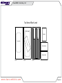
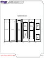
Case 1 of 4
Case Packing - 1 of 4
Graphics
12A 11A
15A15
12 11
Setup Hardware
Halogen Lights
Top View of Each Level
Level 1
Counter Top
Plex Counter
Internal Shelf
Level 2 Level 3

© 2017
www.classicexhibits.com
Order #XXXXX -
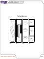
Case 2 of 4
Case Packing - 2 of 4
Graphics
Graphics
Assembled
Door
16/16A
13/13A
17A/17
18
17A/17
Top View of Each Level
Level 1
Header Graphic
Pedestal Infills (x2)
Level 2 Level 4Level 3
Base Plate (x2)
Base Plate (x2)
Base Plate

© 2017
www.classicexhibits.com
Order #XXXXX -
Case 3 of 4
Case Packing - 3 of 4
Top View of Each Level
Level 1
Aero Backwall Frame Bars
Parts 1-10
Monitor Mount

© 2017
www.classicexhibits.com
Order #XXXXX -
Case 4 of 4
Case Packing - 4 of 4
Level 1 Level 2 Level 3 Level 4 Level 5 Level 6
Plex Counter Top Internal Shelf Pedestal
Front Infill
1619
5
7
5A
5
5A
1817
Assembled
Pedestal Side
Assembled
Pedestal Side
Assembled
Pedestal
Door
Assembled
Pedestal
Door
6 (x2)
6A (x2)
Top View of Each Level

© 2017
www.classicexhibits.com
Order #XXXXX -
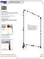
Step 1 of 8
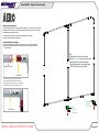
Left Aero Frame Assembly
Connections are made by holding the button
down and sliding the red tube into opposing
tube until the connection is made. To disassemble
push button and pull or twist extrusions apart.
Push-Button
Push-Button
66
6
6
Numbered Label
Using Your Setup Instructions
The Aero Overhead Sign Setup Instructions are created specically for your conguration. They include an
exploded view of the frame which is sequentially numbered. We encourage you to study the instructions
before attempting to assemble your exhibit.
Connections are kept very simple: no tools. Everything assembles with push-button
connectors and pre-connected horizontal sections.
Cleaning and Packing Your Display
1) Use care when cleaning aluminum extrusion or acrylic inserts. Use only non-abrasive cleaners.
2) Retain all packing material. It will make re-packing much easier and will reduce the likelihood
of shipping damage.
1
2
3
4
5
6
7
8
9
10
Steps:
1) Assemble Aero Frame in numerical order.
2) Install Nylon Insert to base plate [1] using a screw.
2) Attach base plate to assembled backwall.
3) Slip pillowcase graphic over assembled frame.
NOTE: Do with care to prevent ripping.
Nylon
Insert for
Aero Frame

© 2017
www.classicexhibits.com
Order #XXXXX -
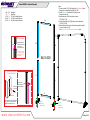
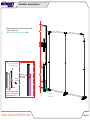
Step 2 of 8
Backwall Assembly
1A
1A
11
11A
12
13
13A
12A
Item
1A
11/11A
12/12A
13/13A
Qty.
2
1/1
1/1
1/1
Description
Base Plate
47.5”h S44 Vertical Extrusion
47.5”h S44 Vertical Extrusion
26”w Z45 Horizontal Extrusion
Steps:
1) Connect verticals [11] & [11A] together. See S44 Connector detail.
Repeat step for assembling verticals [12] & [12A].
2) Install Nylon Insert to base plates [1A] using a screw
through the outer hole.
3) Attach base plates [1A] to the bottom of verticals
[12/12A] & [11/11A].
4) Connect horizontals [13] & [13A] between veritcal assembies
[11/11A] & [12/12A].
5) Attach assembled Aero Frame (with pillowcase graphic installed)
to key hole located in [11A].
See Aero Frame to Vertical Extrusion Attachment detail.
BACK SIDE
Screws
Connector
S44 Connector
Silde extrusion over
connector and rest on
lower vertical;
secure with screws.
**To prevent product loss,
Keep all screws attached
to connector piece after
disassembling
*
Nylon
Insert for
Aero Frame
Nylon
Insert for
Aero Frame
**
Key Hole is on
groove closest to
exterior of exhibit.
Aero Graphic Frame
Insert bolts of aero frame into keyhole
slote in groove of vertical extrusion,
slide aero frame down to secure.
Aero Frame to Vertical
Extrusion Attachment
Bolt Attached
to Aero Frame
*
V20 Connector
*

© 2017
www.classicexhibits.com
Order #XXXXX -
Step 3 of 8
14
15
16
16A
Side Infill
Side Infill
17
17
17A
17A
18
Item
14
15
16/16A
17/17A
18
Qty.
1
1
1/1
2/2
1
Description
37.25”h S44 Vertical Extrusion w/ Door Stop
37.25”h S44 Vertical Extrusion w/ Door Hinges
26”w Horizontal Extrusion
12”w Horizontal Extrusion
29.622”w Mounting Plate
Steps:
1) Attach horizontals [16] & [16A] between verticals [14] & [15].
NOTE: Install [16] at the base of door stop;
Install [16A] at to top of door stop.
2) Connect horizontals [17] between verticals [14] & [15]
and backwall verticals [11].
3) Insert Side Infills between verticals [14] & [15] and
backwall; secure with horizontals [17A].
4) Place cabinet bottom inside assembled kiosk frame.
NOTE: Shelf will rest on lips of horizontals [17].
5) Assemble Plex & Wood counters together.
See Plex Counter Attachment detail.
6) Install assembled counter top to assembled kiosk base.
See Counter Top Attachment detail.
7) Hang door on hinges located on vertical [15].
See Door Attachment detail.
8) Attach monitor mounting plate [18] to verticals [11A] & [12A].
See Monitor Mount Attachment detail.
9) Install header Graphic. NOTE: Will attach using Velcro
Plex Counter Attachment
*
Attach stand-off
barrels to primary
counter top.
Connect plex
counter to primary
counter top using
screw caps.
**DO NOT
OVER TIGHTEN.
PLEX WILL CRACK**
Screw Cap
Plex Counter
Align hole with pin Rotate pin. Spring
will push pin into hole.
Counter Top Attachment
12
*
Door
Hinge
Hinge
Slide pin into
hinge attached
to vertical.
Slide door
hinge over pin.
Door Attachment
*
**
*
*
*
**
*
*
Monitor Mount Attachment
Attach mounting plate
to verticals as shown.
Then attach wall plate
to plate using bolts
& wing nuts
Slide mounting connectors
center into groove. Tighten
setscrew to secure in place.
Setscrew
Setscrew
*
1
2
3
Backwall Workstation Assembly

© 2017
www.classicexhibits.com
Order #XXXXX -
Step 4 of 8
Right Aero Frame Assembly
Connections are made by holding the button
down and sliding the red tube into opposing
tube until the connection is made. To disassemble
push button and pull or twist extrusions apart.
Push-Button
Push-Button
66
6
6
Numbered Label
Using Your Setup Instructions
The Aero Overhead Sign Setup Instructions are created specically for your conguration. They include an
exploded view of the frame which is sequentially numbered. We encourage you to study the instructions
before attempting to assemble your exhibit.
Connections are kept very simple: no tools. Everything assembles with push-button
connectors and pre-connected horizontal sections.
Cleaning and Packing Your Display
1) Use care when cleaning aluminum extrusion or acrylic inserts. Use only non-abrasive cleaners.
2) Retain all packing material. It will make re-packing much easier and will reduce the likelihood
of shipping damage.
19
20
21
28
31
32
30
29
27
22
24
25
26
23
1
1
Steps:
1) Assemble Aero Frame in numerical order
2) Attach Nylon Inserts to base plates using screws.
2) Attach base plates to assembled backwall.
3) Slip pillowcase graphic over assembled frame.
NOTE: DO with care to prevent ripping.
Nylon
Insert for
Aero Frame
Nylon
Insert for
Aero Frame

© 2017
www.classicexhibits.com
Order #XXXXX -
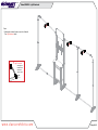
Step 5 of 8
Backwall Assembly Cont.
12A
Nylon
Insert for
Aero Frame
*
Key Hole is on
groove closest to
exterior of exhibit.
Aero Graphic Frame
Insert bolts of aero frame into keyhole
slote in groove of vertical extrusion,
slide aero frame down to secure.
Aero Frame to Vertical
Extrusion Attachment
Bolt Attached
to Aero Frame
*
V20 Connector
1) Attach assembled Aero Frame (with pillowcase graphic installed)
to key hole located in [12A].
See Aero Frame to Vertical Extrusion Attachment detail.

© 2017
www.classicexhibits.com
Order #XXXXX -
Step 6 of 8
Light Attachment
Steps:
1) Attach lights in desired location on top rails of backwall.
See Light Attachment detail.
Light Connection
Attach lights to
backwall where
desired and
tighten in place.
*
*
*
*

© 2017
www.classicexhibits.com
Order #XXXXX -
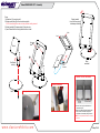
Step 7 of 8
MOD-1371 - Assembly
When
assembled
Steps:
1) Attach base [1] to post using bolt.
2) Attach square plates [4] to curved vertical using bolts.
NOTE: Square plate [4] must rotate to left and right before installing clamshell.
3) Attach clamshells [5] to square plates [4] using hex nuts.
4) Insert iPad and feed wire through holes as shown in detail.
Base
Mount
Wire
Access
iPad
Lock
Lock
Foam Lining
Removed
Home Button Shield
Optional Cover for Home Button
Clamshell Attachment
Baseplate Attachment
1) Remove foam lining from inside bottom of
clamshell as shown.
2) Attach Home Button Shield with double-sided
tape to inside of clamshell, keeping top of
shield flush with clamshell opening as shown.
NOTE: This is a permanent fix and can’t be easily
removed.
Rotate clamshell
to turn iPad from portrait
to landscape orientation
Post Rotates
vertically
Hex
Nuts

© 2017
www.classicexhibits.com
Order #XXXXX -
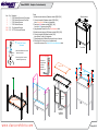
Step 8 of 8
Reception Counter Assembly
1
2
3
4
5
5
6
Cabinet Bottom
Infill
Infill
Infill
6
When Assembled
Front View
Item
1
2
3
4
5/5A
6/6A
Qty.
1
1
1
1
2/2
2/2
Description
37.25”h Vertical Extrusion w/ Door Hinges
37.25”h Vertical Extrusion w/ Door Stop
37.25”h Vertical Extrusion
37.25”h Vertical Extrusion
16”w Horizontal Extrusion
33.7757”w Horizontal Extrusion
Steps:
1) Attach horizontal extursions [5] between verticals [2&3] & [1&4].
2) Connect horizontals [6] between verticals [1&2] & [3&4];
place Cabinet Bottom self onto lip of horizontals.
3) Insert side Infills between verticals [2&3] & [1&4];
insert front Infill between verticals [3&4].
4) Hang Assembled Cabinet Door. See Door Attachment detail.
5) Attach horizontal extrusions [5A] between verticals [2&3] & [1&4].
6) Connect horizontals [6A] between verticals [3&4];
place Cabinet Top onto lip of horizontals.
7) Screw threaded end of Stand-off Barrels into the tops of verticals.
8) Place Upper Plex Counter on top of installed barrels;
secure with screw caps. See Upper Plex Counter Attachment detail.
1) Attach standoff barrels to counter
and secure in place.
2) Secure Upper Plex Counter to
standoffs using screw caps.
Upper Plex Counter
Attachment
Upper Plex
Counter
Standoff
Barrel
Screw
Cap *
Door
Hinge
Hinge
Slide pin into
hinge attached
to vertical.
Slide door
hinge over pin.
Door Attachment
*
Cabinet Top
5A
Assembled
Door Assembled
Door
5A
6A
7
6A
BACK
VIEW
*
*
Upper
Plex Counter
-
 1
1
-
 2
2
-
 3
3
-
 4
4
-
 5
5
-
 6
6
-
 7
7
-
 8
8
-
 9
9
-
 10
10
-
 11
11
-
 12
12
-
 13
13
-
 14
14


Classic Exhibits TF-523 Setup Instructions
- Typ
- Setup Instructions
w innych językach
- English: Classic Exhibits TF-523
Powiązane artykuły
-
Classic Exhibits VK-1112 Setup Instructions
-
-
-
-
-
-
-
-
-
