Crowcon Xgard Bright User's And Operator's Manual
- Typ
- User's And Operator's Manual

Xgard et Xgard IR Détecteurs de gaz,
Manuel de l'utilisateur et de l'opérateur,
M079910 issue 3 Avril 2019
Xgard und Xgard IR Gasdetektoren
Benutzer- und Bedienerhandbuch,
M079910 issue 3 April 2019
Xgard y Xgard IR Detectores de gas
Manual del usuario y del operador,
M079910 issue 3 Abril 2019
Xgard e Xgard IR Rilevatori di gas,
Manuale per utente e operatore,
M079910 issue 3 aprile 2019
Xgard en Xgard IR Gasdetectors,
Handleiding voor gebruikers en operators,
M079910 issue 3 april 2019
Xgard i Xgard IR Detektor gazu,
Podręcznik użytkownika i operatora,
M079910 issue 3 kwiecień 2019
Xgard e Xgard IR Detectores de gás,
Manual do Usuário e Operador,
M079910 issue 3 Abril 2019
M079910
Issue 3 April 2019
Xgard Bright
Gas Detectors with Display and Relays
User and Operator Manual


Xgard Bright
1
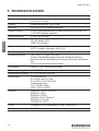
CONTENTS
1. DIAGRAMS ...........................................................................................7
1.1 Certification Labels ........................................................................7
1.2 Dimensions Diagram .....................................................................9
1.3 Exploded View ............................................................................. 11
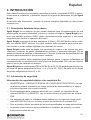
2. Introduction .........................................................................................14
2.1 Product Overview ........................................................................14
2.2 Safety Information .......................................................................14
2.3 Storage instructions .....................................................................15
3. Installation ...........................................................................................16
3.1 Hazardous Area Use ....................................................................16
3.2 Location ........................................................................................16
3.3 Mounting ......................................................................................17
3.4 Internal Electrical Connections ....................................................17
3.5 General Cabling Requirement .....................................................18
3.6 Cabling Requirement 4 to 20 mA Current Loop ..........................18
3.7 Cabling Requirement Multidrop MODBUS ..................................19
3.8 Earthing requirements .................................................................23
4. OPERATION .......................................................................................24
4.1 Operation panel ...........................................................................24
4.2 Screen Indications .......................................................................24
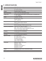
5 Specification ........................................................................................26
Français
1. SCHEMAS ............................................................................................7
1.1 Marques de certification ................................................................7
1.2 Schéma des dimensions ...............................................................9
1.3 Vue éclatée .................................................................................. 11
2. Introduction .........................................................................................27
2.1 Vue d'ensemble du produit ..........................................................27
2.2 Informations de sécurité ..............................................................27
2.3 Storage instructions .....................................................................28
3. Installation ...........................................................................................29
3.1 Utilisation dans des zones dangereuses ......................................29

Xgard Bright
2
3.2 Emplacement ................................................................................29
3.3 Installation ...................................................................................30
3.4 Branchements électriques internes .............................................31
3.5 Besoins de câblage d’ensemble .................................................31
3.6 Exigences de câblage -Boucle de courant 4 à 20 mA ...............31
3.7 Exigences de câblage - MODBUS multipoint ..............................33
3.8 Exigences de mise à la terre .......................................................37
4. UTILISATION ......................................................................................38
4.1 Panneau de commande ..............................................................38
4.2 Indications à l'écran .....................................................................38
5 Specification ........................................................................................40
Deutsch
1. KENNZEICHNUNGEN ..........................................................................7
1.1 Zertifizierungsetiketten ..................................................................7
1.2 Maßskizze .....................................................................................9
1.3 Explosionsansicht ........................................................................ 11
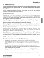
2. EINFÜHRUNG ....................................................................................41
2.1 Produktübersicht ..........................................................................41
2.2 Sicherheitsinformationen .............................................................41
2.3 Hinweise zur Lagerung ................................................................42
3. EINBAU ...............................................................................................43
3.1 Einsatz in Gefahrenbereichen ......................................................43
3.2 Standort ........................................................................................43
3.3 Montage .......................................................................................44
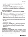
3.4 Interne elektrische Anschlüsse ....................................................45
3.5 Allgemeine Verdrahtungsanforderung ........................................45
3.6 Verdrahtungsanforderungen für die 4- bis 20-mA-Stromschleife 46
3.7 Verdrahtungsanforderungen Multidrop-MODBUS .......................47
3.8 Erdung .........................................................................................51
4. Betrieb .................................................................................................52
4.1 Bedienpanel .................................................................................52
4.2 Bildschirmanzeigen .....................................................................52
5. Technische daten ................................................................................54

Xgard Bright
3
Español
1. DIAGRAMAS ........................................................................................7
1.1 Etiquetas de certificación ..............................................................7
1.2 Dimensiones Diagrama .................................................................9
1.3 Vista en despiece ........................................................................11
2. INTRODUCCIÓN ................................................................................55
2.1 Descripción detallada del producto .............................................55
2.2 Información de seguridad ............................................................55
2.3 Instrucciones de almacenamiento ...............................................56
3. Installation ...........................................................................................57
3.1 Uso en áreas peligrosas ..............................................................57
3.2 Ubicación .....................................................................................57
3.3 Montaje ........................................................................................58
3.4 Conexiones eléctricas internas ...................................................59
3.5 Requisitos generales de cableado ..............................................59
3.6 Requisitos de cableado para circuito de corriente de 4 a 20mA 60
3.7 Requisito de cableado Multidrop MODBUS ................................61
3.8 Requisitos de puesta a tierra ......................................................65
4. OPERACIÓN ......................................................................................66
4.1 Panel operativo ............................................................................66
4.2 Indicaciones de la pantalla ..........................................................66
5. ESPECIFICACIÓN ..............................................................................68
Italiano
1. SCHEMI ................................................................................................7
1.1 Etichette di certificazione ...............................................................7
1.2 Schema dimensioni .......................................................................9
1.3 Vista esplosa ...............................................................................11
2. INTRODUZIONE .................................................................................69
2.1 Panoramica del prodotto .............................................................69
2.2 Informazioni sulla sicurezza ........................................................69
2.3 Istruzioni per la conservazione ....................................................70
3. INSTALLAZIONE ................................................................................71

Xgard Bright
4
3.1 Utilizzo in zone pericolose ...........................................................71
3.2 Ubicazione ...................................................................................71
3.3 Montaggio ....................................................................................72
3.4 Collegamenti elettrici interni ........................................................72
3.5 Requisiti generali di cablaggio .....................................................73
3.6 Requisiti di cablaggio ciclo di corrente da 4 a 20mA ..................73
3.7 Requisiti di cablaggio multidrop MODBUS ..................................74
3.8 Requisiti di messa a terra ............................................................78
4. FUNZIONAMENTO .............................................................................79
4.1 Pannello operativo .......................................................................79
4.2 Indicazioni sullo schermo ............................................................79
5. SPECIFICHE TECNICHE ...................................................................81
Nederlands
1. DIAGRAMMEN .....................................................................................7
1.1 Certificatielabels ............................................................................7
1.2 Afmetingendiagram .......................................................................9
1.3 Opbouwtekening .......................................................................... 11
2. INTRODUCTIE ...................................................................................82
2.1 Productoverzicht ..........................................................................82
2.2 Veiligheidsinformatie ....................................................................82
2.3 Opslaginstructies .........................................................................83
3. INSTALLATIE ......................................................................................84
3.1 Gebruik in een gevaarlijk gebied .................................................84
3.2 Locatie .........................................................................................84
3.3 Montage .......................................................................................85
3.4 Interne elektrische aansluitingen .................................................86
3.5 Algemene kabelvereisten ..............................................................86
3.6 Kabelvereisten 4 tot 20mA stroomlus ..........................................87
3.7 Kabelvereisten Multidrop MODBUS ............................................88
3.8 Aardingsvereisten ........................................................................92
4. BEDIENING ........................................................................................93
4.1 Bedieningspaneel ........................................................................93
4.2 Displaymeldingen ........................................................................93
5. SPECIFICATIE ....................................................................................95

Xgard Bright
5
Polski
1. DIAGRAMY I SCHEMATY ....................................................................7
1.1 Etykiety certyfikacyjne ...................................................................7
1.2 Schemat wymiarowy ......................................................................9
1.3 Widok rozstrzelony ......................................................................11
2. WPROWADZENIE ..............................................................................96
2.1 Opis produktu ..............................................................................96
2.2 Informacje o bezpieczeństwie .....................................................96
2.3 Instrukcje dotyczące przechowywania ........................................97
3. INSTALACJA .......................................................................................98
3.1 Użytkowanie w obszarze niebezpiecznym ..................................98
3.2 Miejsce instalacji ..........................................................................98
3.3 Montaż .........................................................................................99
3.4 Wewnętrzne połączenia elektryczne .........................................100
3.5 Ogólne wymogi dotyczące okablowania ...................................100
3.6 Wymogi dotyczące okablowania pętli prądowej o natężeniu
od 4 do 20 mA ...........................................................................100
3.7 Wymogi dotyczące okablowania w sieci wielopunktowej
MODBUS ...................................................................................102
4. PRACA ..............................................................................................107
4.1 Panel obsługowy .......................................................................107
4.2 Wskazania na ekranie ...............................................................107
5. DANE TECHNICZNE ........................................................................109
Português do Brasil
1. FIGURAS ..............................................................................................7
1.1 Placas de certificação ...................................................................7
1.2 Diagrama de dimensões ...............................................................9
1.3 Vista explodida ............................................................................11
2. INTRODUÇÃO .................................................................................. 110
2.1 Visão geral do produto ..............................................................110
2.2 Informações de Segurança .......................................................110
2.3 Instruções de armazenamento .................................................. 111
3. INSTALAÇÃO ...................................................................................112
3.1 Uso em áreas classificadas .......................................................112

Xgard Bright
6
3.2 Posicionamento .........................................................................112
3.3 Instalação ..................................................................................113
3.4 Ligações elétrica internas ..........................................................113
3.5 Critério gerais de cabeamento ..................................................114
3.6 Critérios de cabeamento – Loop de corrente de 4 a 20mA ......114
3.7 Critérios de cabeamento – MODBUS multiponto ......................115
3.8 Requisitos de aterramento ........................................................119
4. OPERAÇÃO ......................................................................................120
4.1 Painel de operação ...................................................................120
4.2 Indicações na tela .....................................................................120
5. CARACTERÍSTICAS TÉCNICAS .....................................................122

Xgard Bright Certification
7
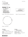
1. DIAGRAMS
1.1 Certification Labels
Diagram 1. ATEX and IECEx certification label Diagram 2. Gas name and range label
Diagram 3. Warning label
Français
1. SCHEMAS
1.1 Marques de certification
Schéma 1 : Marque de certification ATEX
et IECEx
Schéma 2 : Dénomination et plage du gaz
Schéma 3 : Plaque d'avertissement
Deutsch
1. KENNZEICHNUNGEN
1.1 Zertifizierungsetiketten
Abbildung 1 : ATEX- und IECEx-
Zertifizierungsetikett
Abbildung 2 : Gasname und Typenschild
Abbildung 3 : Warnschild

Certification Xgard Bright
8
Español
1. DIAGRAMAS
1.1 Etiquetas de certificación
Diagrama 1: Etiqueta de certificación ATEX
e IECEx
Diagrama 2: Nombre del gas y etiqueta de
la gama
Diagrama 3: Etiqueta de advertencia
Italiano
1. SCHEMI
1.1 Etichette di certificazione
Schema 1: Etichetta di certificazione ATEX
e IECEx
Schema 2: Etichetta nome del gas e
intervallo
Schema 3: Etichetta di avvertenza
Nederlands
1. DIAGRAMMEN
1.1 Certificatielabels
Diagram 1: ATEX en IECEx certificatielabel
Diagram 2: Gasnaam- en bereiklabel
Diagram 3:Waarschuwingslabel
Polski
1. DIAGRAMY I SCHEMATY
1.1 Etykiety certyfikacyjne
Diagram 1: Etykieta certyfikacyjna ATEX i
IECEx
Diagram 2: Etykieta z nazwą i zakresem
gazu
Schemat 3: Etykieta ostrzegawcza
Português do Brasil
1. FIGURAS
1.1 Placas de certificação
Figura 1: Placa de certificação ATEX e
IECEx
Figura 2: Placa de identificação e faixa
nominal do gás
Figura 3: Adesivo de avisos

Xgard Bright Dimensions
9
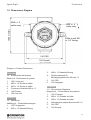
1.2 Dimensions Diagram
M20 x 1.5
cable entry
M20 x 1.5
cable entry
166 Overall
Slots to suit M6
or 1/4” fixings
146 CRS
155.5 Overall
Diagram 4: Product Dimensions
Français
1.2 Schéma des dimensions
Schéma 4 : Dimensions du produit
1. 155.5 Hors tout
2. M20 x 1,5 Entrée de câble
3. M20 x 1.5 Entrée de câble
4. Fentes pour fixations M6 ou ¼”
5. 146 Entraxe
6. 166 Hors tout
Deutsch
1.2 Maßskizze
Abbildung 4 : Produktabmessungen
1. 155.5 Insgesamt
2. M20 x 1,5 Kabeleinführung
3. M20 x 1.5 Kabeleinführung
4. Schlitze passend für
Befestigungselemente M6 oder ¼"
5. 146 CRS
6. 166 Insgesamt
Español
1.2 Dimensiones Diagrama
Diagrama 4 – Dimensiones del producto
1. 155.5 General
2. M20 x 1,5 Entrada de cable
3. M20 x 1.5 Entrada de cable
4. Ranuras para adaptar fijaciones M6 o ¼
5. 146 CRS
6. 166 General

Dimensions Xgard Bright
10
Italiano
1.2 Schema dimensioni
Schema 4 – Dimensioni prodotto
1. 155.5 Totale
2. M20 x 1,5 Ingresso cavo
3. M20 x 1.5 Ingresso cavo
4. Slot adatti a fissaggi M6 o da ¼”
5. 146 CRS
6. 166 Totale
Nederlands
1.2 Afmetingendiagram
Diagram 4 – Productafmetingen
1. 155.5 Totaal
2. M20 x 1,5 Kabelinvoer
3. M20 x 1.5 Kabelinvoer
4. Sleuven voor M6- of ¼"-bevestigingen
5. 146 Middelpunten
6. 166 Totaal
Polski
1.2 Schemat wymiarowy
Diagram 4 - Wymiary produktu
1. 155.5 Ogólne
2. M20 x 1,5 Wpust kablowy
3. M20 x 1.5 Wpust kablowy
4. Szczeliny dopasowane do mocowania
M6 lub ¼ "
5. 146 CRS
6. 166 Ogólne
Português do Brasil
1.2 Diagrama de dimensões
Figura 4 – Dimensões do produto
1. 155.5 Total
2. M20 x 1,5 Entrada de cabo
3. M20 x 1.5 Entrada de cabo
4. Furação para parafusos M6 ou ¼”
5. 146 Entre centros
6. 166 Total

Xgard Bright Exploded view
11
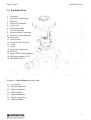
1.3 Exploded View
Diagram 5: Xgard Bright exploded view
1.3 Vue éclatée
1.3 Explosionsansicht
1.3 Vista en despiece
1.3 Vista esplosa
1.3 Opbouwtekening
1.3 Widok rozstrzelony
1.3 Vista explodida
1 Gas label
2 Enclosure lid assembly
3 M4 stud
4 Main PCB assembly
5 Grub screw
6 Certification label
7 Sensor assembly
8 Sensor chamber assembly
9 Enclosure base assembly
10 Wire guide
11 Sensor seals
12 Terminal PCB assembly
13 Ferrite
14 Circlip
15 M4x8 Pan head screw
16 M4 Stud
17 M20-1/2"NPT thread adaptor
18 M4 Spring washer ST-ST
19 M4 Washer ST-ST

Exploded view Xgard Bright
12
Français
1 Marquage du gaz
2 Couvercle du boîtier
3 Goujon M4
4 Carte principale
5 Vis sans tête
6 Etiquette Xgard Bright
7 Capteur
8 Chambre du capteur
9 Base du boîtier
10 Guide-fil
11 Joints de capteur
12 Carte bornier
13 Ferrite
14 Circlip
15 Vis à tête tronconique M4x8
16 Goujon M4
17 Adaptateur fileté M20-1/2"NPT
18 Rondelle élastique M4 inox.
19 Rondelle M4 inox.
Deutsch
1 Gaskennzeichnung
2 Baugruppe Gehäuseabdeckung
3 Bolzen M4
4 Baugruppe Hauptplatine
5 Stifttap
6 Xgard Bright - Etikett
7 Sensorbaugruppe
8 Sensorkammerbaugruppe
9 Baugruppe Gehäuseboden
10 Drahtführung
11 Sensordichtungen
12 Baugruppe Leiterplattenklemmen
13 Ferrit
14 Sicherungsring
15 Flachkopfschraube M4x8
16 Bolzen M4
17 Kreuzteil M20-1/2"NPT
18 M4 Federscheibe ST-ST
19 M4 Unterlegscheibe ST-ST
Español
1 Etiqueta de gas
2 Conjunto tapa de la caja
3 Espárrago M4
4 Conjunto placa de bornes principal
5 Tornillo de sujeción
6 Etiqueta Xgard Bright
7 Conjunto de sensor
8 Conjunto de cámara de sensor
9 Conjunto de la base de la caja
10 Guía de cables
11 Juntas de sensor
12 Conjunto placa de bornes de terminales
13 Ferrita
14 Anillo de ajuste
15 Tornillo de cabeza plana M4x8
16 Espárrago M4
17 Sub paso M20-1/2"NPT
18 Arandela elástica M4 ST-ST
19 Arandela M4 ST-ST
Italiano
1 Etichetta gas
2 Gruppo coperchio involucro
3 Perno M4
4 Gruppo PCB principale
5 Vite senza testa
6 Etichette Xgard Bright
7 Gruppo sensore
8 Gruppo camera sensore
9 Gruppo base involucro
10 Guida filo
11 Guarnizioni sensore
12 Gruppo PCB terminale
13 Ferrite
14 Anello di sicurezza
15 Vite a testa troncoconica M4x8
18 Perno M4
17 Sub crossover M20-1/2" NPT
18 Rondella elastica M4 ST-ST
19 Rondella M4 ST-ST

Xgard Bright Exploded view
13
Nederlands
1 Gaslabel
2 Montage deksel van behuizing
3 M4-bout
4 Montage hoofd-PCB
5 Stifttap
6 Label Xgard Bright
7 Montage sensor
8 Montage sensorkamer
9 Montage basis van behuizing
10 Draadgeleider
11 Sensorafdichtingen
12 Montage terminal-PCB
13 Ferriet
14 Circlip
15 M4x8 halfrondkopschroef
16 M4-bout
17 M20-1/2"NPT cross-over sub
18 M4-veerring ST-ST
19 M4-ring ST-ST
Polski
1 Etykieta gazu
2 Zespół pokrywy obudowy
3 Śruba dwustronna M4
4 Zespół głównej płytki drukowanej
5 Śruba dociskowa
6 Etykieta z certyfikatem
7 Zespół czujnika
8 Zespół komory czujnika
9 Zespół podstawy obudowy
10 Prowadnica drutu
11 Uszczelki czujnika
12 Zespół płytki drukowanej zacisków
13 Ferryt
14 Pierścień Segera
15 Śruba z łbem walcowym M4x8
16 Śruba dwustronna M4
17 Nakrętka przeplotu M20-1/2" NPT
18 M4 Podkładka sprężysta ST-ST
19 M4 Podkładka ST-ST
Português do Brasil
1 Placa de identificação do gás
2 Conjunto da tampa do corpo
3 Parafuso espaçador M4
4 Conj. placa de circuito impresso
principal
5 Parafuso sem cabeça
6 Rótulo de certificação
7 Conj. sensor
8 Conj. câmara do sensor
9 Conj. base do corpo
10 Guia de cabo
11 Anéis de vedação do sensor
12 Conj. placa de circuito impresso das
borneiras
13 Ferrita
14 Anel elástico
15 Parafuso cabeça abaulada M4x8
16 Parafuso espaçador M4
17 Adaptador M20-1/2"NPT
18 Arruela elástica inox M4
19 Arruela inox M4

English
14
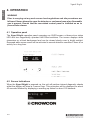
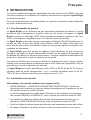
English
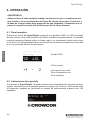
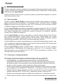
2. INTRODUCTION
This manual contains essential health and safety requirements (EHSRs) and instruc-
tions for the safe installation and operation of the Xgard Bright range of gas detectors.
If more information is required then please refer to the full manual available from https://
www.crowcon.com.
2.1 Product Overview
Xgard Bright is a versatile gas detector for monitoring a wide range of flammable and
toxic gases and oxygen levels. Xgard Bright incorporates a bright OLED (organic light
emitting diode) display and a magnetic wand for easy menu operation.
Xgard Bright provides analogue 4-20mA and RS-485 Modbus signals as standard, with
optional HART interface. Relays are also fitted for activating local alarms or sending
digital signals to control systems.
Xgard Bright may be fitted with electrochemical type toxic or oxygen sensors, pellistor-
type flammable gas sensors or infrared (IR) hydrocarbon or carbon dioxide gas sensors.
Please refer to the product identification label to determine the type of sensor fitted.
Pellistor sensors are designed to detect flammable gases and vapours in concentrations
not exceeding the Lower Explosive Limit (LEL) of the target gas for which the detector
is calibrated.
Xgard Bright is ATEX and IECEx Ex db IIC T6 Gb flameproof certified for use in Zone
1 or 2 hazardous gas areas and Ex tb IIIC T80°C Db for use in Zone 21 or 22 hazard-
ous dust areas.
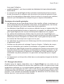
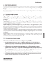
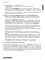
2.2 Safety Information
Safety information relevant to Ex requirements:
• WARNING – POTENTIAL ELECTROSTATIC CHARGING HAZARD. The painted
aluminium enclosure constitutes a potential electrostatic hazard and the equipment
must only be cleaned using a damp cloth.
• The cable gland must be installed before use and must comply with the requirements
of standards EN60019-0 and EN60079-1 with minimum IP66 ingress protection.
• Unused cable entries must be sealed using an ATEX/IECEx Exd certified stopping
plug with minimum IP66 ingress protection.
• Only cables of types specific in these instructions can be used.
• External earthing should be considered and installed according to these instructions
before use.
• WARNING – DO NOT OPEN WHEN AN EXPLOSIVE ATMOSPHERE IS PRESENT.

Xgard Bright
15
English
• The lid on Xgard Bright must be kept tightly closed until power to the detector is
isolated otherwise ignition of a flammable atmosphere can occur. Before removing
the cover for maintenance, ensure the surrounding atmosphere is free of flammable
gases or vapours.
General safety information
• Xgard Bright gas detectors must be installed, operated and maintained in strict
accordance with these instructions, warnings, label information, and within the
limitations stated.
• Xgard Bright detectors are designed to detect gases or vapours in air, and not
inert or oxygen deficient atmospheres. Xgard Bright oxygen detectors can mea-
sure in oxygen deficient atmospheres.
• Electrochemical cells used in toxic and oxygen versions of Xgard Bright contain
small volumes of corrosive electrolyte. Care should be observed when replacing
cells to ensure that the electrolyte does not come into contact with skin or eyes.
• Maintenance and calibration operations must only be performed by qualified ser-
vice personnel.
• Only genuine Crowcon replacement parts must be used, substitute components
may invalidate the certification and warranty of the detector.
• Xgard Bright detectors must be protected from extreme vibration, and direct sun-
light in hot environments as this may cause the temperature of the detector to rise
above its specified limits and cause premature failure. A sunshade is available for
Xgard Bright.
• This equipment must not be used in a Carbon Disulphide atmosphere.
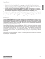
2.3 Storage instructions
Some types of sensor available with Xgard Bright have limited life when left un-
powered and/or may be adversely affected by temperature extremes or environmental
contamination. Ideal storage conditions are 20˚C and 60%RH. Do not expose sensors
to contaminants such as silicones, lead compounds and strong solvents such as isopro-
panol. It is strongly recommended detectors are installed and powered within 3 months
of purchase.

Xgard Bright
16
English
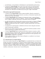
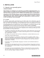
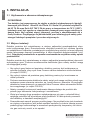
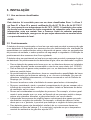
3. INSTALLATION
3.1 Hazardous Area Use
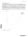
3.2 Location
The detector should be mounted where the gas to be detected is most likely to be
present. The placement of sensors should be determined following advice of experts
having specialist knowledge of gas dispersion, the plant processing equipment as well
as safety and engineering issues. The agreement reached on the locations of sen-
sors should be recorded.
The detector should be mounted where the gas to be detected is most likely to be pre-
sent. The following points should be noted when locating gas detectors:
• To detect gases which are lighter than air, detectors should be mounted at high
level and Crowcon recommend the use of a collector cone (Part No. C01051).
• To detect heavier than air gases, detectors should be mounted at low level.
• When locating detectors consider the possible damage caused by natural events
e.g. rain or flooding. For detectors mounted outdoors Crowcon recommend the use
of a Spray Deflector (Part No. C01052).
• Consider ease of access for functional testing and servicing.
• Consider how the escaping gas may behave due to natural or forced air currents.
Mount detectors in ventilation ducts if appropriate.
• Consider the process conditions. For example, butane is normally heavier than air,
but if released from a process which is at an elevated temperature and/or pres-
sure, the gas may rise rather than fall.
• Location of oxygen sensors requires knowledge of the gas that may displace the
oxygen. For example, carbon dioxide is denser than air and therefore is likely to
displace oxygen from low levels upwards.
• Sensors should be mounted at head height (1.5m nominally) to detect gases of a
similar density to air, assuming that ambient conditions and the temperature of the
target gas are nominally 20˚C.
WARNING
This detector is designed for use in Zone 1 and Zone 2 or Zone 21 and Zone
22 hazardous areas, and is certified Ex db IIC T6 Gb and Ex tb IIIC T80°C Db
for operation up to 70°C (158°F). Installation must be in accordance with the
recognized standards of the appropriate authority in the country concerned. For
further information please contact Crowcon. Prior to carrying out any installa-
tion work ensure local regulations and site procedures are followed.

Xgard Bright
17
English
The placement of sensors should be determined following advice of experts having
specialist knowledge of gas dispersion, the plant processing equipment as well as
safety and engineering issues. The agreement reached on the locations of sensors
should be recorded.
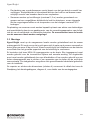
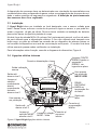
3.3 Mounting
Xgard Bright should be installed at the designated location with the sensor pointing
down. This ensures that dust or water will not collect on the sensor and stop gas enter-
ing the cell. Care should be taken when installing the detector to avoid damaging the
painted surface of the enclosure.
There are two M20x1.5 entry ports on the base. One entry port will be used for power
supply input during normal operation. Unused port will be blocked by blind plug, or can
be used to connect external alarm device or be used for connecting devices to the multi
drop communications. End user will only use certified cable gland for installation.
Refer to the dimension diagram, diagram 4, for mounting hole details.
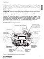
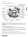
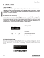
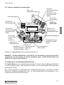
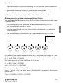
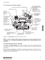
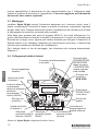
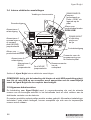
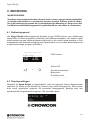
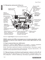
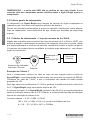
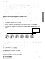
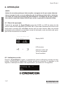
3.4 Internal Electrical Connections
Diagram 6: Xgard Bright internal electrical connections
B A B A
SINK
485
4-20mA LOOP
SIG
–
+
SOURCE
Fault
Level2
Level1
SOUNDER OUT
NO
NC
RT
NO
NC
NO
NC
Vmax=30V Wmax=3W
Xgard Bright Gas Detector
Sounder Out
Power and Loop Connector
Production
use only
Production use
only
NOT USB!
Alarm level 2
Relay Output
Alarm Level 1
Relay Output
Alarm Level 1
Normally Open
or Normally
Closed Jumper
Selection
SOURCE/SINK
Jumpers Fitted to
LHS = SINK, see
lengend on board
RS485 IN/OUT
or End of Line
Terminator
Alarm Level 2
NO/NC Jumper
Selection
Lower Board
Sensor
Connector
Lower Board
Programming
Connector
Fault NO/NC
Jumper Selection
Fault Relay
Output

Xgard Bright
18
English
NOTE: the mini USB socket is not intended for customer use, connecting this to a
computer is likely to damage both Xgard Bright and the computer.
3.5 General Cabling Requirement
Cabling to Xgard Bright must be in accordance with the recognised standards of the
appropriate authority in the country concerned and meet the electrical requirements of
the detector.
Suitable explosion proof glands must be used. Alternative cabling techniques, such as
steel conduit, may be acceptable provided appropriate standards are met.
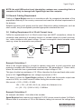
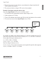
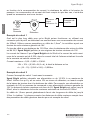
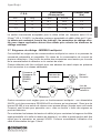
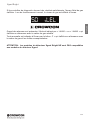
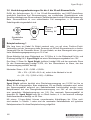
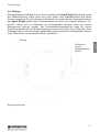
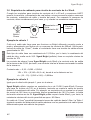
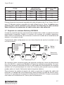
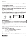
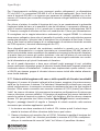
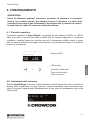
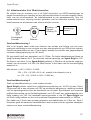
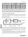
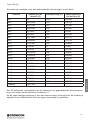
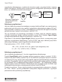
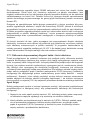
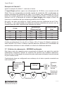
3.6 Cabling Requirement 4 to 20 mA Current Loop
Fulfils the requirements for 4 to 20mA current loop and HART connections, allows for
connection and powering of accessory beacon or sounder subject to current consump-
tion, cable resistance and panel voltage. Current consumption should consider worst
case e.g. when the accessories are powered.
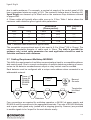
Example Calculation 1
What is the longest cable for a bright to operate using point to point connection and
powering a sounder with 250mA current consumption. Use parameters of 1.5mm
2
cable,
where the controller has a guaranteed minimum output voltage of 18V.
This type of cable has resistance of 12.1Ω/km, therefore the there and back cable resist-
ance is 24.2. Xgard Bright has min voltage requirement of 10V.
The alarm 2 current for Xgard Bright (pellistor) is 95mA and the sounder output max
current is 0.25A, so a total current in alarm driving the sounder output is:
Max current = 0.25 + 0.095 = 0.345A.
18V = 10V + (0.345 x 24.2 x d), where d is distance in km
d = (18 – 10) / (0.345 x 24.2) = 0.958km
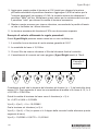
Example Calculation 2
As example calculation 1 but without the sounder.
Xgard Bright pellistor requires a dc supply of 10-30V, at max current in alarm 2 of 95mA.
Ensure there is a minimum of 10V at the detector, taking into account the voltage drop
Xgard Bright
Beacon/
Sounder
Power +V
Signal
Power 0V
Detector
Control
Panel
Strona się ładuje...
Strona się ładuje...
Strona się ładuje...
Strona się ładuje...
Strona się ładuje...
Strona się ładuje...
Strona się ładuje...
Strona się ładuje...
Strona się ładuje...
Strona się ładuje...
Strona się ładuje...
Strona się ładuje...
Strona się ładuje...
Strona się ładuje...
Strona się ładuje...
Strona się ładuje...
Strona się ładuje...
Strona się ładuje...
Strona się ładuje...
Strona się ładuje...
Strona się ładuje...
Strona się ładuje...
Strona się ładuje...
Strona się ładuje...
Strona się ładuje...
Strona się ładuje...
Strona się ładuje...
Strona się ładuje...
Strona się ładuje...
Strona się ładuje...
Strona się ładuje...
Strona się ładuje...
Strona się ładuje...
Strona się ładuje...
Strona się ładuje...
Strona się ładuje...
Strona się ładuje...
Strona się ładuje...
Strona się ładuje...
Strona się ładuje...
Strona się ładuje...
Strona się ładuje...
Strona się ładuje...
Strona się ładuje...
Strona się ładuje...
Strona się ładuje...
Strona się ładuje...
Strona się ładuje...
Strona się ładuje...
Strona się ładuje...
Strona się ładuje...
Strona się ładuje...
Strona się ładuje...
Strona się ładuje...
Strona się ładuje...
Strona się ładuje...
Strona się ładuje...
Strona się ładuje...
Strona się ładuje...
Strona się ładuje...
Strona się ładuje...
Strona się ładuje...
Strona się ładuje...
Strona się ładuje...
Strona się ładuje...
Strona się ładuje...
Strona się ładuje...
Strona się ładuje...
Strona się ładuje...
Strona się ładuje...
Strona się ładuje...
Strona się ładuje...
Strona się ładuje...
Strona się ładuje...
Strona się ładuje...
Strona się ładuje...
Strona się ładuje...
Strona się ładuje...
Strona się ładuje...
Strona się ładuje...
Strona się ładuje...
Strona się ładuje...
Strona się ładuje...
Strona się ładuje...
Strona się ładuje...
Strona się ładuje...
Strona się ładuje...
Strona się ładuje...
Strona się ładuje...
Strona się ładuje...
Strona się ładuje...
Strona się ładuje...
Strona się ładuje...
Strona się ładuje...
Strona się ładuje...
Strona się ładuje...
Strona się ładuje...
Strona się ładuje...
Strona się ładuje...
Strona się ładuje...
Strona się ładuje...
Strona się ładuje...
Strona się ładuje...
Strona się ładuje...
Strona się ładuje...
Strona się ładuje...
Strona się ładuje...
Strona się ładuje...
-
 1
1
-
 2
2
-
 3
3
-
 4
4
-
 5
5
-
 6
6
-
 7
7
-
 8
8
-
 9
9
-
 10
10
-
 11
11
-
 12
12
-
 13
13
-
 14
14
-
 15
15
-
 16
16
-
 17
17
-
 18
18
-
 19
19
-
 20
20
-
 21
21
-
 22
22
-
 23
23
-
 24
24
-
 25
25
-
 26
26
-
 27
27
-
 28
28
-
 29
29
-
 30
30
-
 31
31
-
 32
32
-
 33
33
-
 34
34
-
 35
35
-
 36
36
-
 37
37
-
 38
38
-
 39
39
-
 40
40
-
 41
41
-
 42
42
-
 43
43
-
 44
44
-
 45
45
-
 46
46
-
 47
47
-
 48
48
-
 49
49
-
 50
50
-
 51
51
-
 52
52
-
 53
53
-
 54
54
-
 55
55
-
 56
56
-
 57
57
-
 58
58
-
 59
59
-
 60
60
-
 61
61
-
 62
62
-
 63
63
-
 64
64
-
 65
65
-
 66
66
-
 67
67
-
 68
68
-
 69
69
-
 70
70
-
 71
71
-
 72
72
-
 73
73
-
 74
74
-
 75
75
-
 76
76
-
 77
77
-
 78
78
-
 79
79
-
 80
80
-
 81
81
-
 82
82
-
 83
83
-
 84
84
-
 85
85
-
 86
86
-
 87
87
-
 88
88
-
 89
89
-
 90
90
-
 91
91
-
 92
92
-
 93
93
-
 94
94
-
 95
95
-
 96
96
-
 97
97
-
 98
98
-
 99
99
-
 100
100
-
 101
101
-
 102
102
-
 103
103
-
 104
104
-
 105
105
-
 106
106
-
 107
107
-
 108
108
-
 109
109
-
 110
110
-
 111
111
-
 112
112
-
 113
113
-
 114
114
-
 115
115
-
 116
116
-
 117
117
-
 118
118
-
 119
119
-
 120
120
-
 121
121
-
 122
122
-
 123
123
-
 124
124
-
 125
125
-
 126
126
-
 127
127
-
 128
128


Crowcon Xgard Bright User's And Operator's Manual
- Typ
- User's And Operator's Manual
w innych językach
- español: Crowcon Xgard Bright
- italiano: Crowcon Xgard Bright
- Deutsch: Crowcon Xgard Bright
- português: Crowcon Xgard Bright
- français: Crowcon Xgard Bright
- English: Crowcon Xgard Bright
- Nederlands: Crowcon Xgard Bright
Powiązane artykuły
-
Crowcon Xgard Bright Instrukcja obsługi
-
-
-
Crowcon T4 Skrócona instrukcja obsługi
-
-
-
-
Crowcon XgardIQ Instrukcja obsługi
-
Crowcon Gasman Instrukcja obsługi
Inne dokumenty
-
LG PDRYCB500 Instrukcja obsługi
-
Niko 25466 Instrukcja obsługi
-
Smartwares FGA-13410 Instrukcja obsługi
-
Beta 1760/RSE Instrukcja obsługi
-
PNI GD-01 Gas Detector Instrukcja obsługi
-
Niko 25451 Instrukcja obsługi
-
Niko 3327 Instrukcja obsługi
-
Vanderbilt GM730 Instrukcja instalacji
-
Niko 25342 Instrukcja obsługi
-