
IMAGES P. 45
IMMAGINI PAG. 45
IMAGES PAGE 45
IMÁGENES PÁG. 45
ABBILDUNGEN S. 45
IMAGENS PÁG.45
ILUSTRACJE STR. 45
Instructions and warnings for installation and use
Istruzioni ed avvertenze per l’installazione e l’uso
Instructions et avertissements pour l’installation et l’usage
Anleitungen und Hinweise zu Installation und Einsatz
Instrucciones y advertencias para su instalación y uso
Instruções e advertências para a instalação e utilização
Instrukcje i zalecenia dotyczące instalacji i użytkowania
Garage door opener
Motoriduttore per porte da garage
Motoréducteur pour portes de garage
Motorreductor para puertas de garaje
Garagentorantrieb
Motorredutor para portões de garagem
Motoreduktor do bram garażowych
HALO

EN
2
LIST OF CONTENTS
1
2
3
4
5
6
Safety warnings
2.1
2.2
2.3
2.4
2.5
4.1
4.2
4.3
4.4
4.5
4.6
4.7
4.8
4.9
4.10
4.11
4.12
4.13
4.14
4.15
4.16
4.17
5.1
5.2
Product Introduction
Product description
Composition
Models and technical characteristics
Technical Specications
List of cables required
Preliminary checks
Product installation
Halo assembly and installation with LED rail
3-part rail assembly
Single rail assembly
Connection of the motor casing to the steel
rails
Installation with motor casing on spring
holder shaft or on cross beam
Traditional installation
Manual opening of the door
Fixing the LED rail opening limit stops
Fixing the steel rail opening limit stops
Electrical wiring
Radio controls programming
Learning of opening and closing values
Changing a control unit parameter
Control unit resetting
Hole for access control mechanism
Using the display programmer
KUBE PRO / KUBE wireless module connection
Testing and commissioning
Testing
Commissioning
CE Declaration of Conformity
page 3
page 5
page 5
page 5
page 5
page 6
page 6
page 7
page 7
page 7
page 8
page 8
page 8
page 8
page 8
page 8
page 8
page 8
page 8
page 9
page 10
page 11
page 11
page 11
page 12
page 12
page 13
page 13
page 13
page 95

3
EN
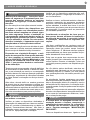
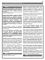
1 - SAFETY WARNINGS
ORIGINAL INSTRUCTIONS - important safety
instructions. Follow the instructions since
incorrect installation can lead to severe inquiry!
Save these instructions.
Read the instructions carefully before proceeding
with installation.
The design and manufacture of the devices
making up the product and the information in
this manual are compliant with current safety
standards. However, incorrect installation
or programming may cause serious injury
to those working on or using the system.
Compliance with the instructions provided
here when installing the product is therefore
extremely important.
If in any doubt regarding installation, do not proceed
and contact the Key Automation Technical Service
for clarications.
Under European legislation, an automatic
door or gate system must comply with the
standards envisaged in the Directive 2006/42/
EC (Machinery Directive) and in particular
standards EN 12453; EN 12635 and EN 13241-
1, which enable declaration of presumed
conformity of the automation system.
Therefore, nal connection of the automation
system to the electrical mains, system testing,
commissioning and routine maintenance must
be performed by skilled, qualied personnel, in
observance of the instructions in the “Testing and
commissioning the automation system” section.
The aforesaid personnel are also responsible for
the tests required to verify the solutions adopted
according to the risks present, and for ensuring
observance of all legal provisions, standards
and regulations, with particular reference to all
requirements of the EN 12453 standard which
establishes the test methods for testing door and
gate automation systems.
Before starting installation, perform the
following checks and assessments:
ensure that every device used to set up the
automation system is suited to the intended system
overall. For this purpose, pay special attention to
the data provided in the “Technical specications”
section. Do not proceed with installation if any one
of these devices is not suitable for its intended
purpose;
check that the devices purchased are sucient to
guarantee system safety and functionality;
perform a risk assessment, including a list of the
essential safety requirements as envisaged in
Annex I of the Machinery Directive, specifying
the solutions adopted. The risk assessment is
one of the documents included in the automation
system’s technical le. This must be compiled by a
professional installer.
Considering the risk situations that may
arise during installation phases and use of
the product, the automation system must
be installed in compliance with the following
safety precautions:
never make modications to any part of the
automation system other than those specied
in this manual. Operations of this type can only
lead to malfunctions. The manufacturer declines
all liability for damage caused by unauthorised
modications to products;
if the power cable is damaged, it must be replaced
by the manufacturer or its after-sales service, or in
all cases by a person with similar qualications, to
prevent all risks;
do not allow parts of the automation system to
be immersed in water or other liquids. During
installation ensure that no liquids are able to enter
the various devices; should this occur, disconnect
the power supply immediately and contact a Key
Automation Service Centre. Use of the automation
system in these conditions may cause hazards;
never place automation system components near
to sources of heat or expose them to naked lights.
This may damage system components and cause
malfunctions, re or hazards;
The drive shall be disconnected from its power
source during cleaning, maintenance and
when replacing parts. If the disconnect device
is not in a visible location, ax a notice stating:
“MAINTENANCE IN PROGRESS”:
connect all devices to an electric power line
equipped with an earthing system;
the product cannot be considered to provide
ATTENTION !
ATTENTION !
ATTENTION !

EN
4
eective protection against intrusion. If eective
protection is required, the automation system must
be combined with other devices;
the product may not be used until the automation
system “commissioning” procedure has been
performed as specied in the “Automation system
testing and commissioning” section;
the system power supply line must include a
circuit breaker device with a contact gap allowing
complete disconnection in the conditions specied
by class III overvoltage;
use unions with IP55 or higher protection when
connecting hoses, pipes or cable glands;
the electrical system upstream of the automation
system must comply with the relevant regulations
and be constructed to good workmanship
standards;
this appliance can be used by children aged from
8 years and above and persons with reduced
physical, sensory or mental capabilities or lack
of experience and knowledge if they have been
given supervision or instruction concerning use of
the appliance in a safe way and understand the
hazards involved;
before starting the automation system, ensure that
there is no-one in the immediate vicinity;
before proceeding with any cleaning or maintenance
work on the automation system, disconnect it from
the electrical mains;
special care must be taken to avoid crushing
between the part operated by the automation
system and any xed parts around it;
children must be supervised to ensure that they do
not play with the equipment;
drive is not to be used with doors having openings
exceeding 50mm in diameter or having edges or
protruding parts a person could grip or stand on;
that the drive cannot be used with a driven part
incorporating a wicket door unless the drive can
only be operated with the wicket door in the safe
position;
in the case of detection of an obstacle during its
closing travel, the garage door reverses its travel
direction, releasing the obstacle until it opens
completely;
install the actuating member for the manual
release at a height less than 1,8m. If removable,
the actuating member should be stored in direct
vicinity of the door;
install any xed control at a height of at least 1,5m
and within sight of the door but away from moving
parts;
permanently x the labels warning against
entrapment in a prominent place or near any xed
controls (Fig. 1 Pag. 54);
after installation, ensure that the mechanism is
properly adjusted and that the drive reverses or
the object can be freed when the door contacts a
50mm high object placed on the oor (for drives
incorporating an entrapment protection system
depending on contact with the bottom edge of the
door);
after installation, ensure that parts of the door do
not extend over public footpaths or roads;
when the appliance is provided with a separate stop
button, that stop button shall be unambiguously
identiable.
Frequently examine the installation for
imbalance where applicable and signs of wear
or damage to cables, springs and mounting.
Do not use if repair or adjustment is necessary.
Packaging components (cardboard, plastic,
etc.), duly separated, must be placed in the
appropriate bins. Device components such as
electronic boards, metal parts, batteries, etc.
must be separated and dierentiated. For the
methods of disposal, the rules in force in the
place of installation must be applied. DO NOT
DISPOSE IN THE ENVIRONMENT!
Key Automation reserves the right to amend
these instructions if necessary; they and/or
any more recent versions are available at www.
keyautomation.com
ATTENTION !
ATTENTION !

5
EN
2 - PRODUCT INTRODUCTION
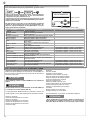
2.1 - Product description
2.2 - Composition
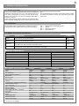
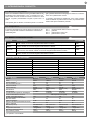
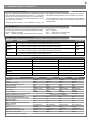
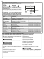
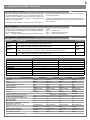
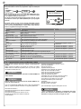
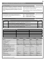
2.3 - Models and technical characteristics
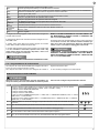
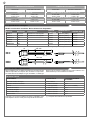
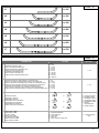
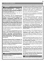
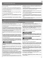
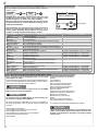
Halo is an irreversible electromechanical gearmotor suitable for
automating overhead doors up to 17m2 and sectional doors up to
19m2. Halo is equipped with an encoder, a control unit and an inte-
grated 4-channel receiver. The rail is pre-assembled with a belt, in
one piece or 3 pieces.
A special aluminium rail, powder coated and with integrated LEDs,
allows for garage lighting both during movement and at any other
The automation system for garage doors is contained in two boxes
forming the automation system’s and the rail system’s packaging:
time.
The special at design of the motor housing also makes it possible
to install it less invasively near the door cross beam or the spring
holder shaft.
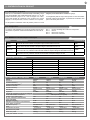
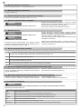
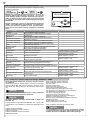
CODE DESCRIPTION POWER
900HA8 For sectional doors up to 11 sqm (with 3 m guide) or 12 sqm (with 4 m guide), a 24 Vdc motor and a
control unit with an integrated receiver 800N
900HA12 For sectional doors up to 16 sqm (with 3 m guide) or 19 sqm (with 4 m guide), a 24 Vdc motor and a
control unit with an integrated receiver 1200N
900HA12E For sectional doors up to 16 sqm (with 3 m guide) or 19 sqm (with 4 m guide), “Low Energy” with 24
Vdc motor and a control unit with an integrated receiver 1200N
900HA12L For sectional doors up to 16 sqm (with 3 m guide) or 19 sqm (with 4 m guide), a 24 Vdc motor and a
control unit with an integrated receiver and 120Vac power supply 1200N
HEAD/RAIL COMPATIBILITY
HA8 HA12 - HA12E - HA12L
900RAB31 X X
900RAB3X1P X X
900RAB41 X X
900RAB2X2P X X
900RAB61 X
900RAL31 X
900RAL41 X
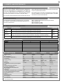
TECHNICAL SPECIFICATIONS 900HA8 900HA12 900HA12E 900HA12L
Speed 15 cm/s 15 cm/s 15 cm/s 15 cm/s
Force 800 N 1200 N 1200 N 1200 N
Max cycles/hour (1) 20 20 20 20
Max consecutive cycles/hour (1) 10 10 10 10
Rated power 80w 100w 100w 100w
Stand-by power 5,5 W 5,5 W <0,5 W 5,5 W
Power supply 230vac (±10%)
50hz 230vac (±10%)
50hz 230vac (±10%)
50hz 120vac (±10%)
50/60hz
Flashing 3 W Max 3 W Max 3 W Max 3 W Max
Courtesy light on rail with integrated LEDs - 40 W Max 40 W Max 40 W Max
Accessories power output 100mA (24 Vdc not regulated)
Fuse 1 power line 1AT 1AT 1AT 2AT
Max no. of transmitters that can be stored
ROLLING CODE 90 90 90 90
Degree of protection IP 20 IP 20 IP 20 IP 20
Use in highly acid, saline or explosive
atmosphere No No No No
Dimensions (L x D x H): 235-330-84 mm 235-330-84 mm 235-330-84 mm 235-330-84 mm
Weight 6,25 Kg 6,8 Kg 6,8 Kg 6,8 Kg
Working temperature -10°C/+45°C -10°C/+45°C -10°C/+45°C -10°C/+45°C
Maximum door size 12 m219 m219 m219 m2
Maximum door weight 120 Kg 200 Kg 200 Kg 200 Kg
(1) for door up to 2m in height
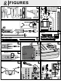
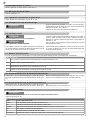
FIG. 1 head package contents with parts list
FIG. 2 LED rail
FIG. 3 single piece steel rail
FIG. 4 3-piece steel rail

EN
6
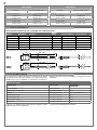
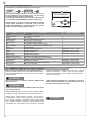
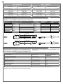
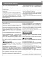
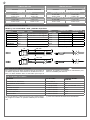
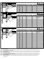
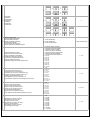
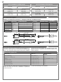
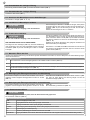
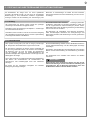
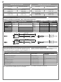
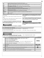
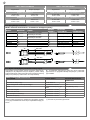
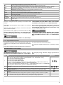
2.4 - Technical specications
The data shown may vary according to the sliding and balancing performance of the door and the type of rail used.
Recommended model and use - Available rails and dimensions
MODEL MATERIAL NOTES DRIVE
TYPE TOTAL LENGTH RAIL TRAVEL
900RAL31 Aluminium With integrated LED lighting Belt 3090 mm (1x3m) 2660 mm
900RAL41 Aluminium With integrated LED lighting Belt 4090 mm (1x4m) 3660 mm
900RAB3X1P Steel Belt 3100 mm (3x1.03m) 2670 mm
900RAB31 Steel Belt 3100 mm (1x3.1m) 2670 mm
900RAB41 Steel Belt 4100 mm (1x4.1m) 3670 mm
900RAB2X2P Steel Belt 4100 mm (2x2.05 m) 3670 mm
2.5 - List of cables required
In a typical plant, the cables necessary for connection of the various
devices are shown in the cable list table. The cables used must be
suitable for the type of installation, for example we recommend a
H03VV-F type cable for indoor installation or H07RN-F for outdoor
installation.
CABLE LIST TABLE
CONNECTION CABLE TYPE MAX LENGTH
PERMITTED
Power supply line Schuko CEE 7/4
Flashing light, courtesy light 1 x cable 3 x 0.5 mm220 m
Antenna 1 x RG58 type cable 20 m (recommended < 5 m)
Transmitter photocells 1 x cable 2 x 0.5 mm220 m
Receiver photocells 1 x cable 4 x 0.5 mm220 m
Radio sensitive edge (*) 1 x cable 4 x 0.5 mm2<2 m
Key selector 1 x cable 2 x 0.5 mm220 m
If there is not a suitable power outlet near the equipment, contact
qualied personnel for its installation.
(*): refer to the manufacturer’s instructions
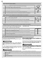
USE LIMITS
Sectional Up-and-over slide-away
900HA8 with 3 m rail
S max=11m²
H max = 2,6m
S max=10m²
H max = 3m
900HA8 with 4 m rail
S max=12m²
H max = 3,6m
S max=11m²
H max = 3,4m
USE LIMITS
Sectional Up-and-over slide-away
900HA12, 900HA12E, 900HA12L with 3 m rail
S max=16m²
H max = 2,6m
S max=16m²
H max = 3m
900HA12, 900HA12E, 900HA12L with 4 m rail
S max=19m²
H max = 3,6m
S max=17m²
H max = 3,4m
RAL31
RAL41
RAB31
RAB41
330 3065 / 4065
114
235
P MAX = 84 mm
330 3075 / 4075
70,5
235
P MAX = 84 mm

7
EN
3 - PRELIMINARY CHECKS
Before installing the product, check and verify the following points:
- Check that the door is suitable for automated control
- The weight and the size of the door must be within the limits of
use specied for the automation system in which the product is in-
tegrated
- Check that the mechanical safety stops required on the door are
solid and properly installed
- Check that the product xing area is not subject to ooding
- Heavy acidity or salinity conditions or proximity to sources of heat
may cause product malfunction
- In case of extreme weather conditions (for example snow, ice,
sudden temperature changes, high temperatures) friction could in-
crease and consequently, the force necessary for movement and
initial start-up could be higher than that required under standard
conditions
- Check that the manual movement of the door is smooth and free
from peak friction points and that there is no risk of the door going
o its rails
- Check that the door is well balanced and will not move notwith-
standing the position it is left in
- Check that the power line to which the product is to be connected
is equipped with an adequate safety earthing system and protected
by a magnetothermic circuit breaker and dierential cuto device
- Provide a disconnecting device in the system power supply net-
work with a contact opening gap that allows for complete discon-
nection in the conditions provided by the overvoltage category III.
- Check that all the material used for installation complies with the
regulations in force
4 - PRODUCT INSTALLATION
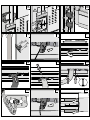
4.1 - Halo assembly and installation with LED rail
Before starting assembly operations, make sure to have all the nec-
essary tools available (FIG. 5).
Place the rail on a at surface, protecting it from any scratches. Re-
move the plastic cap and take out the contents.
Cause the transmission pulley to slide until the screw protrudes
more from the end of the rail, unscrew the nut, insert the tension-
ing spring and re-tighten the nut until belt tension is ensured (FIG.
6, 7). Bring the head close to the rail and place it on a at surface,
protecting the bottom cover from potential scratches. Remove the
rear cover by applying pressure to the two points indicated (FIG. 8).
Remove the white cover (FIG. 9), use a utility knife to cut the two
rectangles on the white cover and remove them (FIG.10).
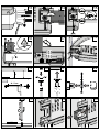
Open the indicated door by cutting the plastic material with a utility
knife and lifting it gently (FIG. 11), then insert the LED adjustment
board (contained in the rail package) with the cables already insert-
ed (FIG. 2, 12). Gently close back the cover. Place the cables in the
special slots, inserting the cable without connector into the indicated
hole (FIG. 12).
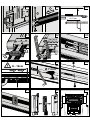
Insert the metal adapter inside the hole on the rail with the help of a
rubber mallet (FIG. 13) then insert the rail on the head, taking care to
match the adapter grooving to the motor pin’s (FIG. 14) and connect
the connector (FIG. 15).
Check that the cables are inside their provided seats before
positioning and tightening the upper plate (FIG. 16) to avoid
crushing them. Tighten the 4 cross-head screws.
Open the side door, remove the cable and connect the wires to the
control unit (FIG. 17). Close back the side door.
Place the motor on the spring holder shaft (FIG. 18), lift the rail until
parallel to the ground, measure the dimension A (distance between
the rail and ceiling) and then cut the threaded bar to a measure cor-
responding to A - 5 cm (FIG. 19). The threaded bar and the xing
components are included with the LED rail.
Assemble the components of the threaded bar (FIG. 20). Fix the
threaded bar to the ceiling using suitable screws or anchors (not
supplied) (FIG. 21). Assemble and insert the lower part of the brack-
et into the rail causing it to slide in the slots (FIG. 22) then insert the
plastic cap in the rail.
Connect the threaded bar to the hexagonal nut at the top of the rail,
turning the bar, until it goes in by about 1 cm, in order to have a per-
fectly horizontal rail. Then tighten the nuts in the indicated sequence
(FIG. 23).
Insert the long screws and turn them by hand, to allow the nuts to t
back inside their seats (FIG. 24). Allow the screws to protrude by a
few millimetres, so that the bracket can be inserted in the provided
slot. Use the slot to position the bracket on the cross beam and mark
the positions of the holes (FIG. 25).
Move the motor to the side and x the bracket using suitable screws
and anchors (not supplied) (FIG. 26).
Reposition the motor on the bracket.
Now turn the long side screws only slightly (FIG. 38). Do not
tighten hard so as not to damage the nut seats.
Tighten the lock nuts (FIG. 27) hard, while holding the screws in
place with a hexagonal wrench.
Do not turn the screws to avoid breaking the nut seats, turn
exclusively the lock nuts until tight.
Fix the lower jaws (FIG. 28).
Fix the bracket to the upper part of the door, in a central position
(FIG. 29) and exactly in the middle of the C-shaped bracket (FIG.
26). Measure the indicated dimensions (TAB. 1A) and put together
the connecting arm with the indicated parts (TAB. 2).
Release the slider by operating the release cord (FIG. 30).
Pull the slider clip, insert the curved arm and its pin inside it (FIG.
31, 32, 33, 34) and tighten the 2 countersunk-head screws to close
the clip. Also tighten the 2 countersunk head screws symmetrically
at the opposite end of the slider.
Connect the arm to the door (FIG. 35), then reset the slider by mov-
ing the release cord to allow the lever to retract and lock it, moving
the door manually until it engages (FIG. 36).
Remove the transparent stickers provided to protect the rail and
LED diuser proles (FIG 37).
After completing the programming (next paragraphs), x the safety
screw (FIG. 52) and place the white cover back (FIG. 53).
ATTENTION !
ATTENTION !
ATTENTION !

EN
8
For anything not indicated, please refer to paragraph 4.1
DO NOT REMOVE THE REAR COVER!
Fix the bracket to the cross beam (FIG. 26), then connect the steel
rail using one of the two long screws supplied (FIG. 39) and to follow
the instructions of TAB. 1C and TAB. 2.
Raise the rail until parallel to the ground, measure the dimension A
and then cut the two ceiling brackets as shown: dimension A + 3 cm
(FIG. 40). Insert the quick coupling plate, then connect it to the ceil-
ing brackets (FIG. 41, 42).
Fix the brackets to the ceiling using suitable screws and anchors
(not supplied).
Follow the instructions in section 4.1 from FIG. 29 to FIG. 35, by
inserting the arm in the slit of the slider previously cut open with a
utility knife (FIG. 43).
4.2 - 3-part rail assembly
4.3 - Single rail assembly
4.4 - Connection of the motor casing to the steel rails
4.5 - Installation with motor casing on cross beam
4.6 - Standard installation
Assemble the rail (FIG. 4) then pull the belt (FIG. 7)
Pull the belt (FIG. 7)
Follow the instructions in section 4.1 (FIG. 13, 14, 16)
For anything not indicated, please refer to paragraph 4.1
Follow the instructions in section 4.1 from FIG. 25; please be careful
not to connect the bracket to the slot, but to the single hole (FIG. 38)
and to follow the instructions of TAB. 1B and TAB. 2.
Then continue following the instructions in section 4.1
In the event of a power failure and if the optional buer battery is not available, to unlock the automation system:
4.7 - Manual opening of the door
PHASE DESCRIPTION
1 Pull the cord in order to bring the release lever to its vertical position (FIG. 30)
2 Lift or lower the door manually
3To reset the automation system, move the cord so as to allow the release lever to t fully back into the pulling slider (FIG. 36)
4 Lift or lower the door manually until it engages with the rail
4.8 - Fixing the LED rail opening limit stop
Unlock the slider, manually lift the door until it is in its maximum pos-
sible indicated opening position H - 10 cm (FIG. 44).
Mark the end position of the slider with a pencil (FIG. 45), then drill a
hole and x with the screw (FIG. 46).
4.9 - Fixing the steel rail opening limit stop
Unlock the slider, manually lift the door until it is in its maximum pos-
sible indicated opening position H - 10 cm (FIG. 44).
Firmly fasten the limit stops (FIG. 47).
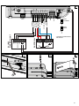
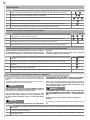
4.10 - Electrical wiring
Before connecting, check that the control unit is not powered
Follow the connection instructions (FIG. 48)
ATTENTION !
ATTENTION !
ATTENTION !
ATTENTION !
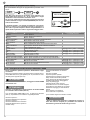
ELECTRICAL WIRING
COM FLASH, LED output common
FLASH Flashing output 24Vdc (not regulated), maximum 3W
LED Courtesy light output 24Vdc (not regulated), maximum 20W
PH-POW Photocell power positive output 24Vdc (not regulated), maximum 100mA
NEG Photocell power negative output
PH Photocells (closing) NC contact between PH and COM
EDGE/EDGE Sensitive edge input, NC contact, 8k2 resistive or 8k2 double resistive (parallel)

9
EN
The LED ashing light must be connected to the COM and FLASH
terminals.
The courtesy light must be connected to the COM and LED termi-
nals.
The SBS step by step contact must be connected to the COM and
SBS terminals (normally open NO contact).
The photocell contact must be connected to the COM and PH ter-
minals. To bypass the photocell, move the left-hand dip switch
upwards. After having activated the dip switch, the LEDs L1
and L2 start to ash at a fast rate.
CONFIRM INPUT PH DEACTIVATION BY PRESSING THE MENU
AND RADIO BUTTONS SIMULTANEOUSLY AND HOLDING
THEM DOWN UNTIL THE LEDs L1 AND L2 STOP FLASHING.
The inputs of the sensitive EDGE must be connected to the EDGE
and EDGE terminals. To bypass the sensitive edge, move the
right-hand dip switch upwards. After having activated the dip
switch, the LEDs L1 and L2 start to ash at a fast rate.
CONFIRM INPUT EDGE DEACTIVATION BY PRESSING THE
MENU AND RADIO BUTTONS SIMULTANEOUSLY AND HOLD-
ING THEM DOWN UNTIL THE LEDs L1 AND L2 STOP FLASH-
ING.
ATTENTION !
ATTENTION !
SBS STEP BY STEP NO contact control between SBS and COM
Open/Stop/Close/Stop control or control based on software selection
STOP NC contact STOP between STOP and COM. The contact can be activated at any time and will immediately lock the
automation system, disabling any function including automatic closing
COM SBS, STOP input common
L1 RED LED indicating programming of control panel parameters
MENU Key for programming control panel parameters
RADIO Key for programming integrated radio parameters
L2 GREEN LED indicating programming of radio parameters
KUBE/DYL DYL and KUBE connector
SBS SBS (STEP-BY-STEP) key for automation system control
DIP1/PH
DIP2/EDGE Dip switch for disabling safety devices (PH, EDGE) see FIG. 48
SHIELD Antenna - sheath -
ANT Antenna - signal -
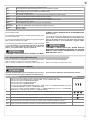
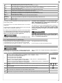
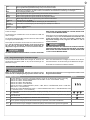
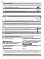
4.11 - Memorising a remote control
If you have a KUBE PRO wireless module, connect it to the control
unit (FIG. 49, 50) and follow the instructions on the screen.
If you have a DYL cable module, connect it to the control unit and
MEMORISING A REMOTE CONTROL
By activating the memorising phase any transmitter within the
range can be stored. To reduce the receiver range, disconnect
ATTENTION !
follow the instructions on the screen.
Otherwise proceed as described below:
the antenna temporarily.
PHASE DESCRIPTION EXAMPLE
1
Press and release the RADIO button for a number of times equal to the feature that you wish to activate:
1 time for the feature: SBS (STEP-BY-STEP or OPEN - STOP - CLOSE - STOP),
2 times for the feature: PARTIAL OPENING,
3 times for the feature: OPENING ONLY,
4 times for the feature: LIGHT ON/OFF,
5 times for the feature: PRE-SET (key 1 = SBS, key 2 = PARTIAL OPENING, key 3 = OPENING ONLY,
key 4 = LIGHT ON/OFF)
6 times for the feature: WALL BUTTON (key 1 = CLOSES/STOP, key 2 = OPENS/STOP,
key 3 = VENTILATION, key 4 = LIGHT ON/OFF)
+ +
2LED L2 ashes a number of times corresponding to the selected output at 1 second intervals 1s► 1s►
3Within 10 seconds, press and hold the button of the radio control that you wish to store for at least 2 seconds >2s
4If the memorisation has been successful, the LED L2 will emit a long ash >3s
5 To memorize another remote control on the same output, repeat point 3
Note After 10 seconds of inactivity, the receiver automatically exits the programming phase

EN
10
PHASE DESCRIPTION
1 Program a remote control if you do not have a remote control already stored or work the SBS button of the control unit
2 If the slider has never been moved by hand, the door, with the slider attached to the rail, must be in its partial opening position
3Press the SBS button of a stored remote control or the SBS button on the control unit or an external button connected to the SBS
input of the control unit
If you have a KUBE PRO wireless module, connect it to the control
unit (FIG. 49, 50) and follow the instructions on the screen.
If you have a DYL cable module, connect it to the control unit and
follow the instructions on the screen.
If you had previously connected the KUBE PRO module, KUBE
or the DYL programmer, power the device o for a few seconds
to be able to use the manual procedure.
The photocell contact must be connected to the COM and PH ter-
minals. To bypass the photocell, move the left-hand dip switch
upwards. After having activated the dip switch, the LEDs L1
and L2 start to ash at a fast rate.
CONFIRM INPUT PH DEACTIVATION BY PRESSING THE MENU
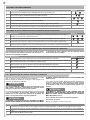
DELETING A REMOTE CONTROL
CLEARING THE ENTIRE RECEIVER MEMORY/RECEIVER RESET
REMOTE MEMORISATION OF A REMOTE CONTROL WITH A REMOTE CONTROL ALREADY MEMORISED
ATTENTION !
ATTENTION !
ATTENTION !
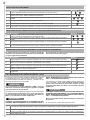
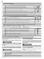
4.12 - Learning opening and closing values
A transmitter can be memorised without accessing the receiv-
er. The user needs to have a transmitter memorised previously,
after which the procedure is as described below. The remote
copy procedure must be carried out in the area served by the
receiver.
AND RADIO BUTTONS SIMULTANEOUSLY AND HOLDING
THEM DOWN UNTIL THE LEDs L1 AND L2 STOP FLASHING.
The inputs of the sensitive EDGE must be connected to the EDGE
and EDGE terminals. To bypass the sensitive edge, move the
right-hand dip switch upwards. After having activated the dip
switch, the LEDs L1 and L2 start to ash at a fast rate.
CONFIRM INPUT EDGE DEACTIVATION BY PRESSING THE
MENU AND RADIO BUTTONS SIMULTANEOUSLY AND HOLD-
ING THEM DOWN UNTIL THE LEDs L1 AND L2 STOP FLASH-
ING.
Note: Led intensity will descrease during movement of the door
Otherwise proceed as described below:
PHASE DESCRIPTION EXAMPLE
1 Press the RADIO button until the LED L2 lights up (about 3 seconds) >3s ►
2Within 10 seconds, press and hold a button of the remote control that you wish to delete until the LED L2 on
the receiver goes o. Release the remote control button ►
3After about 1 second from releasing the button the LED L2 on the receiver starts to ash 0,5s 0,5s
4Conrm deleting by pressing the RADIO button
5If deleting has been successful, the LED L2 will emit one long ash >3s
Note After 10 seconds of inactivity, the receiver automatically exits the deleting phase
PHASE DESCRIPTION EXAMPLE
1Press and hold the RADIO button until the LED L2 lights up (about 3 seconds) and then goes o (about 3
seconds). Release the button >3s ► >3s ►
2After about 1 second from releasing the button the LED L2 on the receiver starts to ash 1s ► 1s ►
3To delete all the memory, press the RADIO button upon the third ash
4If deleting/resetting has been successful the LED L2 will emit one long ash
PHASE DESCRIPTION EXAMPLE
1 Press and hold the button of the new radio control that you wish to store for at least 5 seconds >5s
2Press and hold the button of the old radio control to be copied for at least 3 seconds (if the previous phase
1 was successful, the automation system will not move) >3s
3 Press and hold the button of the new remote control that you wish to store for at least 3 seconds >3s
4Press and hold the button of the old remote control to be copied for at least 3 seconds to conrm and exit
the programming phase >3s
Note After 10 seconds of inactivity, the receiver automatically exits the programming phase

11
EN
PHASE DESCRIPTION
1 Press the MENU button a number of times corresponding to the parameter to be changed (TAB. 3 - P. 51)
2LED L1 emits quick ashes followed by a pause corresponding to the parameter to be changed
3 Press and hold down MENU for more than 3 seconds
4The LED L1 remains o
5 Release the MENU key
6The LED L1 will start emitting long ashes, the number of ashes matches the maximum settable parameter value. At the end of
the last ash the procedure ends without any parameter change
7Briey press the MENU button upon the ash corresponding to the desired parameter value
8If the procedure is successful, LED L1 will emit a long ash, otherwise it will ash repeatedly at a fast rate
PHASE DESCRIPTION
1Press and hold the MENU button until the LED L1 lights up and then goes o
2 Release the MENU key
3LED L1 will start emitting long ashes
4Press the MENU button again upon the 3rd ash
5If the procedure is successful, LED L1 will emit a long ash, otherwise it will ash repeatedly at a fast rate
4.13 - Changing a control unit parameter
4.14 - Control unit parameter resetting
4
The door must perform a slow-speed opening
If the door closes, press the button again to stop it then press it again to reverse the direction. This procedure can only
be successful if the rst operation is an opening stroke and it ends with the slider impacting the mechanical stop previ-
ously positioned
5The door reaches full opening position as the slider reaches its mechanical stop, stops for a second and then restarts in the closing
direction until the operation is complete
6 The values are stored
7Perform AT LEAST one second full opening operation and one second full closing operation from the limit stop point without
breaks, to allow the control unit to store the motor stress along the travel
8If the automation system fails to complete the operation, check that there are no mechanical jams along the travel, the balancing
of the door and possibly change and reduce the obstacle sensitivity parameter
9
To reset opening and closing values:
press and hold the MENU button until the LED L1 lights up and then goes o.
Release the MENU button. LED L1 emits long ashes.
Press the MENU button again upon the:
5th ash for the HALO 800 motor
6th ash for the HALO 1200 motor
If the procedure is successful, LED L1 will emit a long ash, otherwise it will ash repeatedly at a fast rate
Repeat the procedure from point 4 above
If you have a KUBE PRO wireless module, connect it to the control
unit (FIG. 49, 50) and follow the instructions on the screen.
If you have a DYL cable module, connect it to the control unit and
follow the instructions on the screen.
Otherwise proceed as described below:
ATTENTION !
4.15 - Hole for access control mechanism
Close the garage door (controlled by the motor); using a pencil,
mark the position of the slider on the opposite side with respect to
the door. Release the slider, then drill a 10 mm hole in the centre of
the rail where marked (FIG. 51).
Check the ecient operation of the mechanism by closing the door
manually, resetting the slider and trying to open the garage door
manually.

EN
12
courtesy light operation - operation after power failure - ashing
activation for maintenance - default - input lock with password -
receiver lock with password - stop contact.to change follow the in-
structions on the screen.
* After adjusting the parameter it is mandatory to control at
least two complete operations to allow the control unit to store
the motor stress throughout the stroke
4.17 - KUBE PRO / KUBE wireless module connection
Before carrying out any operation, power o the equipment.
Remove the plastic protection cover of the KUBE module connector.
Remove the plastic shells (FIG. 49) and insert the card in its special
input slot (FIG. 50).
Once removed from its container, handle the KUBE module
with extreme care.
Carefully check the position of the KUBE module on the control
unit connector (FIG. 50).
With the KUBE PRO and DYL programmers it is possible to change,
in addition to the parameters (TAB. 3), the following parameters:
opening speed* - slowing speed in opening* - closing speed* -
slowing speed in closing* - slowing extent in opening* - slowing ex-
tent in closing* - phototest - sensitive edge test - partial opening
extent - garage ventilation function extent - partial automatic closing
time - ventilation automatic closing time - ashing operation mode
- pre-ashing time - light intensity at end of movement - integrated
ATTENTION !
ATTENTION !
ATTENTION !
4.16 - Using the display programmer
To customise the programmer’s language, proceed as follows:
N.B.: When the display is turned on for the rst time, the user
will be prompted to select a language. Press ▲ or ▼ to select
the desired language and then conrm with V.
If no language is selected (press the X key), the control unit will
use the default language (ENGLISH) until the next power-on.
In normal mode, i.e. when the system is powered on normally
and the display programmer is connected, press X until the
wording “Key Automation” is displayed. In this way, you will
be able to view the following status messages:
OPTIONS
DISPLAY
LANGUAGE
SELECTION
CONFIRM
SCROLL UP
KEY AUTOMATION
SCROLL DOWN
CANCEL
EVENT DESCRIPTION FLASHING INDICATION AND
CONTROL UNIT CONTROL LEDS
opening Door opening
ventilation opening Door opening for ventilation
closing Door closing
automatic closing Open door with timed closing active
stop in closing Door stopped in closing phase
stop in opening Door stopped in opening phase
open Door fully open without automatic closing
open in ventilation Door open in ventilation without automatic closing
closed Door fully closed
programming During the programming phase 2 fast ashes + pause + 1 ash
obstacle Detected motor obstacle 4 fast ashes + pause 3 times
photo! Photocell operation 2 fast ashes + pause 3 times
sensitive edge! Sensitive edge operation 5 fast ashes + pause 3 times
partial opening Partial opening in progress
partial automatic closing Partial door opening with active timed closing
ventilation automatic closing Open door in ventilation with active timed closing
FLASH/LED error FLASH and LED output overload 6 fast ashes + pause 3 times
phototest error Phototest error detected 3 fast ashes + pause 3 times
limit switch error! Limit switch/mechanical stop error detected 8 fast ashes + pause 3 times
memory error Memory error detected 10 fast ashes + pause 3 times

13
EN
draw up the declaration of conformity, the instructions and
precautions for use for the end user and the system maintenance
plan and consign them to the end user;
ensure that the user has fully understood how to operate the system
in automatic, manual and emergency modes;
the end user must also be informed in writing about any risks and
hazards still present;
After detecting an obstacle, the gate or door stops du-
ring its opening travel and automatic closure is disabled; to
restart operation, the user must press the control button or use
the transmitter.
5 - TESTING AND COMMISSIONING THE AUTOMATION SYSTEM
The system must be tested by a qualied technician, who must
perform the tests required by the relevant standards in relation
to the risks present, to check that the installation complies with
the relevant regulatory requirements, especially the EN12453
standard which species the test methods for gate and door
automation systems.
WARNING!
5.2 - Commissioning
Once all (and not just some) of the system devices have passed the
testing procedure, the system can be commissioned;
the system’s technical dossier must be produced and kept for 10
years. It must contain the electrical wiring diagram, a drawing or
photograph of the system, the analysis of the risks and the solutions
adopted to deal with them, the manufacturer’s declaration of con-
formity for all connected devices, the operator’s manual for every
device and the system maintenance plan:
x a dataplate with the details of the automation, the name of
the person who commissioned it, the serial number and year of
construction and the CE marking on the gate or door:
also t a plate specifying the procedure for releasing the system by
hand:
5.1 - Testing
All system components must be tested following the procedures
described in their respective operator’s manuals
ensure that the recommendations in Chapter 1 - Safety Warnings -
have been complied with
check that the gate or door is able to move freely once the
automation system has been released and is well balanced,
meaning that it will remain stationary when released in any position;
check that all connected devices (photocells, sensitive edges, emer-
gency buttons, etc.) are operating correctly by performing gate or
door opening, closing and stop tests using the connected control
devices (transmitters, buttons or switches);
perform the impact measurements as required by the EN12453
standard, adjusting the control unit’s speed, motor force and
deceleration functions if the measurements do not give the required
results, until the correct setting is obtained.

14
IT
INDICE
1
2
3
4
5
6
Avvertenze per la sicurezza
2.1
2.2
2.3
2.4
2.5
4.1
4.2
4.3
4.4
4.5
4.6
4.7
4.8
4.9
4.10
4.11
4.12
4.13
4.14
4.15
4.16
4.17
5.1
5.2
Introduzione al prodotto
Descrizione del prodotto
Composizione
Modelli e caratteristiche tecniche
Speciche tecniche
Elenco cavi necessari
Veriche preliminari
Installazione del prodotto
Assemblaggio ed installazione Halo con guida
LED
Assemblaggio della guida in 3 parti
Assembraggio della guida unica
Collegamento del corpo motore alle guide in
acciaio
Installazione con corpo motore su albero
portamolle o su architrave
Installazione classica
Apertura manuale della porta
Fissaggio del necorsa di apertura della guida led
Fissaggio del necorsa di apertura della guida in
acciaio
Collegamenti elettrici
Programmazione dei radiocomandi
Apprendimento delle quote di apertura e chiusura
Modica di un parametro della centrale
Reset della centrale
Foro per meccanismo antintrusione
Utilizzo del programmatore display
Collegamento modulo wireless KUBE PRO /
KUBE
Collaudo e messa in servizio
Collaudo
Messa in servizio
Dichiarazione CE di conformità
pag. 15
pag. 17
pag. 17
pag. 17
pag. 17
pag. 18
pag. 18
pag. 19
pag. 19
pag. 19
pag. 20
pag. 20
pag. 20
pag. 20
pag. 20
pag. 20
pag. 20
pag. 20
pag. 20
pag. 21
pag. 22
pag. 23
pag. 23
pag. 23
pag. 24
pag. 24
pag. 25
pag. 25
pag. 25
pag. 95

15
IT
1 - AVVERTENZE PER LA SICUREZZA
ISTRUZIONI ORIGINALI – importanti istruzioni
di sicurezza. Seguire tutte le istruzioni perchè
una scorretta installazione può portare a lesio-
ni gravi! Conservare queste istruzioni.
Leggere attentamente le istruzioni prima di ese-
guire l’installazione.
La progettazione e la fabbricazione dei dispo-
sitivi che compongono il prodotto e le informa-
zioni contenute nel presente manuale rispet-
tano le normative vigenti sulla sicurezza. Ciò
nonostante un’installazione e una programma-
zione errata possono causare gravi ferite alle
persone che eseguono il lavoro e a quelle che
useranno l’impianto. Per questo motivo, du-
rante l’installazione, è importante seguire at-
tentamente tutte le istruzioni riportate in que-
sto manuale.
Non procedere con l’installazione se si hanno dub-
bi di qualunque natura e richiedere eventuali chia-
rimenti al Servizio Assistenza Key Automation.
Per la legislazione Europea la realizzazione di
una porta automatica o un cancello automatico
deve rispettare le norme previste dalla Diretti-
va 2006/42/CE (Direttiva Macchine) e in partico-
lare, le norme EN 12453; EN 12635 e EN 13241-
1, che consentono di dichiarare la conformità
dell’automazione.
In considerazione di ciò, il collegamento deniti-
vo dell’automatismo alla rete elettrica, il collaudo
dell’impianto, la sua messa in servizio e la manu-
tenzione periodica devono essere eseguiti da per-
sonale qualicato ed esperto, rispettando le istru-
zioni riportate nel riquadro “Collaudo e messa in
servizio dell’automazione”.
Inoltre, egli dovrà farsi carico di stabilire anche le
prove previste in funzione dei rischi presenti e do-
vrà vericare il rispetto di quanto previsto da leggi,
normative e regolamenti: in particolare, il rispetto
di tutti i requisiti della norma EN 12453 che stabili-
sce i metodi di prova per la verica degli automati-
smi per porte e cancelli.
Prima di iniziare l’installazione, eettuare le
seguenti analisi e veriche:
vericare che i singoli dispositivi destinati all’au-
tomazione siano adatti all’impianto da realizzare.
Al riguardo, controllare con particolare attenzione i
dati riportati nel capitolo “Caratteristiche tecniche”.
Non eettuare l’installazione se anche uno solo di
questi dispositivi non è adatto all’uso;
vericare se i dispositivi acquistati sono sucienti
a garantire la sicurezza dell’impianto e la sua fun-
zionalità;
eseguire l’analisi dei rischi che deve comprendere
anche l’elenco dei requisiti essenziali di sicurez-
za riportati nell’Allegato I della Direttiva Macchine,
indicando le soluzioni adottate. L’analisi dei rischi
è uno dei documenti che costituiscono il fascico-
lo tecnico dell’automazione. Questo dev’essere
compilato da un installatore professionista.
Considerando le situazioni di rischio che pos-
sono vericarsi durante le fasi di installazione
e di uso del prodotto è necessario installare
l’automazione osservando le seguenti avver-
tenze:
non eseguire modiche su nessuna parte dell’au-
tomatismo se non quelle previste nel presente
manuale. Operazioni di questo tipo possono solo
causare malfunzionamenti. Il costruttore declina
ogni responsabilità per danni derivanti da prodotti
modicati arbitrariamente;
evitare che le parti dei componenti dell’automazio-
ne possano venire immerse in acqua o in altre so-
stanze liquide. Durante l’installazione evitare che i
liquidi possano penetrare all’interno dei dispositivi
presenti;
se il cavo di alimentazione risulta danneggiato
esso deve essere sostituito dal costruttore o dal
suo servizio di assistenza tecnica o comunque da
una persona con qualica similare in modo da pre-
venire ogni rischio;
se sostanze liquide penetrano all’interno delle par-
ti dei componenti dell’automazione, scollegare im-
mediatamente l’alimentazione elettrica e rivolgersi
al Servizio Assistenza Key Automation. L’utilizzo
dell’automazione in tali condizioni può causare si-
tuazioni di pericolo;
non mettere i vari componenti dell’automazione
vicino a fonti di calore né esporli a amme libere.
Tali azioni possono danneggiarli ed essere causa
di malfunzionamenti, incendio o situazioni di peri-
colo;
L’unità deve essere scollegata dalla fonte di alimen-
tazione durante la pulizia, la manutenzione e la so-
stituzione di componenti. Se il dispositivo di scon-
nessione non è a vista, apporre un cartello con la
seguente dicitura: “MANUTENZIONE IN CORSO”:
ATTENZIONE !
ATTENZIONE !
ATTENZIONE !

16
IT
tutti i dispositivi devono essere collegati ad una li-
nea di alimentazione elettrica dotata di messa a
terra di sicurezza;
il prodotto non può essere considerato un ecace
sistema di protezione contro l’intrusione. Se de-
siderate proteggervi ecacemente, è necessario
integrare l’automazione con altri dispositivi;
il prodotto può essere utilizzato esclusivamente
dopo che è stata eettuata la “messa in servizio”
dell’automazione, come previsto nel paragrafo
“Collaudo e messa in servizio dell’automazione”;
prevedere nella rete di alimentazione dell’impianto
un dispositivo di disconnessione con una distanza
di apertura dei contatti che consenta la disconnes-
sione completa nelle condizioni dettate dalla cate-
goria di sovratensione III;
per la connessione di tubi rigidi e essibili o passa-
cavi utilizzare raccordi conformi al grado di prote-
zione IP55 o superiore;
l’impianto elettrico a monte dell’automazione deve
rispondere alle vigenti normative ed essere ese-
guito a regola d’arte;
l’apparecchio può essere utilizzato da bambini di
età non inferiore a 8 anni e da persone con ridot-
te capacità siche, sensoriali o mentali, o prive di
esperienza o della necessaria consapevolezza,
purché sotto sorveglianza oppure dopo che le
stesse abbiano ricevuto istruzioni relative all’uso
sicuro dell’apparecchio e alla comprensione dei
pericoli ad esso inerenti;
prima di avviare l’automazione assicurarsi che le
persone non siano nelle immediate vicinanze;
prima di procedere a qualsiasi operazione di puli-
zia e manutenzione dell’automazione eseguire la
disconnessione dalla rete elettrica;
fare particolare attenzione per evitare lo schiaccia-
mento tra la parte guidata ed eventuali elementi
ssi circostanti;
i bambini devono essere sorvegliati per sincerarsi
che non giochino con l’apparecchio;
il meccanismo di azionamento non deve essere
usato per porte aventi un raggio di apertura supe-
riore a 50 mm, oppure aventi bordi o sporgenze su
cui una persona potrebbe salire o ai quali aggrap-
parsi;
l’apparecchio non può essere utilizzato con una
porta guidata che incorpora una porta pedonale;
nel caso di rilevamento ostacolo durante la mano-
vra di chiusura, il portone inverte la corsa liberan-
do l’ostacolo no ad aprirsi completamente;
installare l’attuatore per il rilascio manuale a un’al-
tezza massima di 1,8m. Se removibile, l’attuatore
deve essere riposto nelle immediate vicinanze del-
la porta;
installare qualsiasi comando sso a un’altezza mi-
nima di 1,5m e in vista sulla porta, ma lontano da
parti in movimento;
applicare in modo permanente e in un punto chia-
ramente visibile, o vicino a qualsiasi comando s-
so, le targhette che mettono in guardia contro il
rischio di intrappolamento (Fig. 1 Pag. 54);
dopo l’installazione, accertarsi che il meccanismo
sia regolato correttamente e che l’azionamento in-
verta il senso di marcia, oppure che sia possibile
rimuovere dal pavimento un oggetto di 50 mm di
altezza, quando la porta entra a contatto con l’og-
getto (per meccanismi di azionamento con sistema
integrato di protezione anti-intrappolamento attiva-
to dal contatto con il bordo inferiore della porta);
dopo l’installazione, vericare che nessun punto
della porta sporga sul marciapiede o sulla via pub-
blica;
qualora il dispositivo sia dotato di pulsate separato
di arresto, tale pulsante dovrà essere chiaramente
identicabile.
Esaminare periodicamente l’impianto per ve-
ricare la presenza di sbilanciamenti e segni
di usura meccanica, danneggiamento di cavi,
molle, parti di sostegno.
Non utilizzare se è necessaria riparazione o re-
golazione.
Componenti dell’imballo (cartone, plastica,
ecc.), debitamente separati, devono essere
conferiti negli appositi cassonetti. I componen-
ti del dispositivo come schede elettroniche,
parti metalliche, batterie, ecc., vanno separati
e dierenziati. Per le modalità di smaltimen-
to devono essere applicate le regole vigenti
nel luogo d’installazione. NON DISPERDERE
NELL’AMBIENTE!
Key Automation si riserva il diritto di modi-
care le presenti istruzioni qualora necessario,
queste e/o versione superiore si possono tro-
vare sul sito www.keyautomation.com
ATTENZIONE !
ATTENZIONE !

IT
17
2 - INTRODUZIONE AL PRODOTTO
2.1 - Descrizione del prodotto
2.2 - Composizione
2.3 - Modelli e caratteristiche tecniche
Halo è un motoriduttore elettromeccanico irreversibile adatto ad au-
tomatizzare portoni basculanti no a 17m2 e sezionali no a 19m2.
Halo è dotato di encoder, centrale di comando e ricevitore a 4 canali
integrati. La guida è preassemblata a cinghia, in pezzo unico o 3
pezzi.
Una speciale guida in alluminio, verniciata a polveri e con led inte-
Il sistema di automazione per porte da garage è contenuto in due
scatole composte dalla confezione del sistema di automazione e
quella della guida:
grati, permette l’illuminazione del garage sia durante la movimenta-
zione che in qualsiasi altro momento.
La speciale conformazione appiattita del corpo motore permette
inoltre di installarlo in posizione meno invasiva, in prossimità dell’ar-
chitrave della porta e dell’albero portamolle.
CODICE DESCRIZIONE POTENZA
900HA8 Per porte sezionali no a 11 m2 (con guida da 3 m) o 12 m2 (con guida da 4 m), motore 24 Vdc, forza
800 N, centrale con ricevente integrata ed alimentazione a 230Vac 800N
900HA12 Per porte sezionali no a 16 m2 (con guida da 3 m) o 19 m2 (con guida da 4 m), motore 24 Vdc, forza
1200 N, centrale con ricevente integrata ed alimentazione a 230Vac 1200N
900HA12E Per porte sezionali no a 16 m2 (con guida da 3 m) o 19 m2 (con guida da 4 m), “Low Energy” con
motore 24 Vdc, forza 1200 N, centrale con ricevente integrata ed alimentazione a 230Vac 1200N
900HA12L Per porte sezionali no a 16 m2 (con guida da 3 m) o 19 m2 (con guida da 4 m), motore 24 Vdc, forza
1200 N, centrale con ricevente integrata e alimentazione 120 Vac 1200N
DATI TECNICI 900HA8 900HA12 900HA12E 900HA12L
Velocità 15 cm/s 15 cm/s 15 cm/s 15 cm/s
Forza 800 N 1200 N 1200 N 1200 N
Cicli/ora massimi (1) 20 20 20 20
Cicli consecutivi/ora max (1) 10 10 10 10
Potenza nominale 80w 100w 100w 100w
Potenza stand-by 5,5 W 5,5 W <0,5 W 5,5 W
Alimentazione 230vac (±10%)
50hz 230vac (±10%)
50hz 230vac (±10%)
50hz 120vac (±10%)
50/60hz
Lampeggiante 3 W Max 3 W Max 3 W Max 3 W Max
Luce di cortesia su guida con led integrati - 40 W Max 40 W Max 40 W Max
Uscita di alimentazione accessori 100mA (24 Vdc non regolati)
Fusibile 1 linea alimentazione 1AT 1AT 1AT 2AT
N° max trasmettitori memorizzabili
ROLLING CODE 90 90 90 90
Grado di protezione IP 20 IP 20 IP 20 IP 20
Utilizzo in atmosfera particolarmente acida,
salina o esplosiva No No No No
Dimensioni (L-P-H) 235-330-84 mm 235-330-84 mm 235-330-84 mm 235-330-84 mm
Peso 6,25 Kg 6,8 Kg 6,8 Kg 6,8 Kg
Temperatura di esercizio -10°C/+45°C -10°C/+45°C -10°C/+45°C -10°C/+45°C
Dimensione massima portone 12 m219 m219 m219 m2
Peso massimo portone 120 Kg 200 Kg 200 Kg 200 Kg
(1) per porta no a 2m di altezza
FIG. 1 contenuto imballo testa con elenco componenti
FIG. 2 guida led
FIG. 3 guida acciaio in pezzo unico
FIG. 4 guida acciaio in 3 pezzi
COMPATIBILITÁ TESTA/GUIDA
HA8 HA12 - HA12E - HA12L
900RAB31 X X
900RAB3X1P X X
900RAB41 X X
900RAB2X2P X X
900RAB61 X
900RAL31 X
900RAL41 X

18
IT
2.4 - Speciche tecniche
I dati indicati possono variare in base alla scorrevolezza e bilanciatura del portone e dal tipo di guida utilizzato.
Modello e uso consigliato - Guida e dimensioni disponibili
MODELLO MATERIALE NOTE TIPOLOGIA
TRAZIONE LUNGHEZZA
TOTALE CORSA DELLA
GUIDA
900RAL31 Alluminio Con illuminazione a led integrati Cinghia 3090 mm (1x3m) 2660 mm
900RAL41 Alluminio Con illuminazione a led integrati Cinghia 4090 mm (1x4m) 3660 mm
900RAB3X1P Acciaio Cinghia 3100 mm (3x1.03m) 2670 mm
900RAB31 Acciaio Cinghia 3100 mm (1x3.1m) 2670 mm
900RAB41 Acciaio Cinghia 4100 mm (1x4.1m) 3670 mm
900RAB2X2P Acciaio Cinghia 4100 mm (2x2.05 m) 3670 mm
2.5 - Elenco cavi necessari
Nell’impianto tipico i cavi necessari per i collegamenti dei vari dispo-
sitivi sono indicati nella tabella elenco cavi. I cavi utilizzati devono
essere adatti al tipo di installazione, ad esempio si consiglia un cavo
tipo H03VV-F per posa in ambienti interni oppure H07RN-F se po-
sato all’esterno.
TABELLA ELENCO CAVI
COLLEGAMENTO TIPO DI CAVO LUNGHEZZA MASSIMA
CONSENTITA
Linea elettrica di alimentazione Schuko CEE 7/4
Lampeggiante, luce cortesia 1 x cavo 3 x 0,5 mm220 m
Antenna 1 x cavo tipo RG58 20 m (consigliato < 5 m)
Fotocellule trasmettitore 1 x cavo 2 x 0,5 mm220 m
Fotocellule ricevitore 1 x cavo 4 x 0,5 mm220 m
Bordo sensibile radio (*) 1 x cavo 4 x 0,5 mm2<2 m
Selettore a chiave 1 x cavo 2 x 0,5 mm220 m
Se in prossimità dell'apparecchiatura non fosse presente una ade-
guata presa, per la sua installazione rivolgersi a personale qualica-
to.
(*): fare riferimento alle istruzione del produttore
LIMITI D’IMPIEGO
Sezionale Basculante debordante
900HA8 con guida da 3 m
S max=11m²
H max = 2,6m
S max=10m²
H max = 3m
900HA8 con guida da 4 m
S max=12m²
H max = 3,6m
S max=11m²
H max = 3,4m
LIMITI D’IMPIEGO
Sezionale Basculante debordante
900HA12, 900HA12E, 900HA12L con guida da 3 m
S max=16m²
H max = 2,6m
S max=16m²
H max = 3m
900HA12, 900HA12E, 900HA12L con guida da 4 m
S max=19m²
H max = 3,6m
S max=17m²
H max = 3,4m
RAL31
RAL41
RAB31
RAB41
330 3065 / 4065
114
235
P MAX = 84 mm
330 3075 / 4075
70,5
235
P MAX = 84 mm

19
IT
3 - VERIFICHE PRELIMINARI
Prima di installare il prodotto vericare e controllare i seguenti punti:
- Controllare che la porta sia adatta ad essere automatizzata
- Il peso e la dimensione della porta deve rientrare nei limiti d’im-
piego specicati per l’automazione su cui viene installato il prodotto
- Controllare la presenza e la solidità degli arresti meccanici di sicu-
rezza della porta
- Vericare che la zona di ssaggio del prodotto non sia soggetta
ad allagamenti
- Condizioni di elevata acidità o salinità o la vicinanza a fonti di calo-
re potrebbero causare malfunzionamenti del prodotto
- In caso di condizioni climatiche estreme (per esempio in presenza
di neve, ghiaccio, elevata escursione termica, temperature eleva-
te) gli attriti potrebbero aumentare e quindi la forza necessaria per
la movimentazione e lo spunto iniziale potrebbe essere superiori a
quella necessaria in condizioni normali
- Controllare che la movimentazione manuale della porta sia uida
e priva di zone di maggiore attrito o vi sia rischio di deragliamento
della stessa
- Controllare che la porta sia in equilibrio e rimanga quindi ferma se
lasciata in qualsiasi posizione
- Vericare che la linea elettrica a cui sarà collegato il prodotto sia
provvista di opportuna messa a terra di sicurezza e protetta da un
dispositivo magnetotermico e dierenziale
- Prevedere nella rete di alimentazione dell'impianto un dispositi-
vo di disconnessione con una distanza di apertura dei contatti che
consenta la disconnessione completa nelle condizioni dettate dalla
categoria di sovratensione III.
- Vericare che tutto il materiale utilizzato per l’installazione sia con-
forme alle normative vigenti
4 - INSTALLAZIONE DEL PRODOTTO
4.1 - Assemblaggio ed installazione Halo con guida LED
Prima di iniziare l’assemblaggio vericare di avere a disposizione
tutti gli attrezzi necessari (FIG. 5).
Posizionare la guida su una supercie piana, proteggendola da
eventuali graature. Togliere il tappo in plastica ed estrarne il con-
tenuto.
Far scorrere la puleggia di rinvio no a far sporgere maggiormente
la vite dall’estremità della guida, svitare il dado, inserire la molla di
tensionamento e serrare il dado no a tendere la cinghia (FIG. 6,
7). Avvicinare la testa alla guida e posarla su una supercie piana,
proteggendo il coperchio inferiore da potenziali graature. Rimuo-
vere il coperchio posteriore premendo sui due punti indicati (FIG. 8).
Togliere il coperchio bianco (FIG. 9), tagliare con un cutter i due
rettangoli sul coperchio bianco e rimuoverli (FIG. 10).
Aprire lo sportello indicato tagliando la plastica con un cutter e sol-
levandola con delicatezza (FIG. 11), quindi inserire la scheda di re-
golazione dei led (contenuta nella confezione della guida) con i cavi
già innestati (FIG. 2, 12). Richiudere con delicatezza il coperchio.
Posizionare i cavi nelle apposite feritoie, inserendo il cavo senza
connettore nel foro indicato (FIG. 12).
Inserire l’adattatore metallico all’interno del foro sulla guida aiutan-
dosi con un martello di gomma (FIG. 13) quindi inserire la guida
sulla testa, avendo cura di far combaciare i millerighe dell’adattatore
con quelli del perno motore (FIG. 14) e collegare il connettore (FIG.
15) .
Vericare che i cavi siano all’interno delle sedi predisposte pri-
ma di posizionare e serrare la piastra superiore (FIG. 16) per
evitare schiacciamenti degli stessi. Serrare le 4 viti a croce.
Aprire lo sportello laterale, slare il cavo e collegare i li alla centrale
(FIG. 17). Richiudere lo sportello.
Appoggiare il motore sull’albero portamolle (FIG. 18), sollevare la
guida portandola parallela al terreno, misurare la quota A (distanza
tra guida e sotto) e quindi tagliare la barra lettata della quota A
- 5 cm (FIG. 19). La barra lettata e i componenti di ssaggio sono
compresi nella guida a LED.
Assemblare i componenti della barra lettata (FIG. 20). Fissare la
barra lettata al sotto utilizzando adeguate viti o tasselli (non in
dotazione) (FIG. 21). Assemblare ed inserire la parte inferiore della
staa nella guida facendola scorrere nelle feritoie (FIG. 22) quindi
inserire il tappo in plastica nella guida.
Collegare la barra lettata al dado esagonale alto sulla guida, fa-
cendo girare la barra, no a farla entrare per circa 1 cm e avere
così la guida perfettamente orizzontale. Quindi serrare i dadi con la
sequenza indicata (FIG. 23).
Inserire le viti lunghe ed avvitarle a mano, per permettere ai dadi di
rientrare all’interno della sede (FIG. 24). Lasciare che le viti sporga-
no di pochi millimetri, in modo da poter inserire la staa sull’asola
predisposta. Utilizzare l’asola per posizionare la staa sull’architrave
e segnare le posizioni dei fori (FIG. 25).
Spostare il motore di lato e ssare la staa utilizzando adeguate viti
e tasselli (non in dotazione) (FIG. 26).
Riposizionare il motore sulla staa.
Avvitare ora le viti laterali lunghe solo no a sentirle puntate
(FIG. 38). Non serrare con forza per non rompere la sede dei
dadi.
Avvitare i contro-dadi (FIG. 27) e serrarli a fondo, tenendo ferme le
viti con una chiave esagonale.
Non girare le viti per evitare la rottura delle sedi dei dadi, girare
esclusivamente i contro-dadi per serrare.
Fissare le ganasce inferiori (FIG. 28).
Fissare la staa alla parte superiore della porta, in posizione cen-
trale (FIG. 29) ed esattamente al centro della staa a C (FIG. 26).
Prendere le misure indicate (TAB. 1A) e comporre il braccio di colle-
gamento con le parti indicate (TAB. 2).
Sbloccare il carrello agendo sul cordino di sblocco (FIG. 30).
Tirare il ponticello del carrello, inserire il braccio curvo e relativo per-
no all’interno (FIG. 31, 32, 33, 34) e avvitare le 2 viti a testa svasata
di chiusura del ponticello. Avvitare anche le 2 viti a testa svasata
simmetricamente all’altra estremità del carrello.
Collegare il braccio alla porta (FIG. 35), quindi riarmare il carrello
muovendo il cordino di sblocco per permettere alla leva di rientrare e
bloccarlo e muovere la porta manualmente no all’aggancio (FIG. 36).
Rimuovere gli adesivi trasparenti di protezione dei proli diusori dei
led e della guida (FIG. 37).
Dopo aver eseguito la programmazione (paragra successivi) ssa-
re la vite di sicurezza (FIG. 52) ed inserire il coperchio bianco (FIG.
53).
ATTENZIONE !
ATTENZIONE !
ATTENZIONE !

20
IT
Per quanto non indicato fare riferimento al paragrafo 4.1
NON SMONTARE IL COPERCHIO POSTERIORE!
Fissare la staa all’architrave (FIG. 26), quindi collegare la guida in
acciaio utilizzando una delle due viti lunghe in dotazione (FIG. 39) e
seguendo le indicazioni di TAB. 1C e TAB. 2.
Sollevare la guida portandola parallela al terreno, misurare la quota
A e quindi tagliare le due stae a sotto come indicato: quota A + 3
cm (FIG. 40). Inserire la piastra ad aggancio rapido, quindi collegar-
la alle stae a sotto (FIG. 41, 42).
Fissare le stae al sotto utilizzando adeguate viti e tasselli (non in
dotazione).
Seguire il paragrafo 4.1 dalla FIG. 29 alla FIG. 35, inserendo il brac-
cio sull’ asola del carrello precedentemente aperta tramite un cutter
(FIG. 43).
4.2 - Assemblaggio della guida in 3 parti
4.3 - Assemblaggio della guida unica
4.4 - Collegamento del corpo motore alle guide in acciaio
4.5 - Installazione con corpo motore su architrave
4.6 - Installazione classica
Assemblare la guida (FIG. 4) quindi tirare la cinghia (FIG. 7)
Tirare la cinghia (FIG. 7)
Seguire il paragrafo 4.1 (FIG. 13, 14, 16)
Per quanto non indicato fare riferimento al paragrafo 4.1
In caso di interruzione di corrente e se non fosse presente la batteria tampone opzionale, per sbloccare l’automazione:
4.7 - Apertura manuale della porta
FASE DESCRIZIONE
1 Tirare il cordino portando la leva di sblocco in posizione verticale (FIG. 30)
2 Sollevare o abbassare la porta manualmente
3Per riarmare l’automazione muovere il cordino in modo da permettere alla leva di sblocco di rientrare completamente all’interno
del carrello di trascinamento (FIG. 36)
4Alzare o abbassare manualmente la porta no ad agganciarla alla guida
Seguire le indicazioni del paragrafo 4.1 da FIG. 25, collegando però
la staa non sull’asola ma sul foro singolo (FIG. 38) e seguendo le
indicazioni di TAB. 1B e TAB. 2.
Proseguire poi seguendo le indicazioni del paragrafo 4.1
4.8 - Fissaggio del necorsa di apertura della guida LED
Sbloccare il carrello, sollevare manualmente la porta no a portarla
nella posizione di massima apertura possibile indicata H - 10 cm
(FIG. 44).
Segnare la posizione di ne del carrello con una matita (FIG. 45),
quindi praticare un foro con un trapano e ssare con la vite (FIG. 46).
4.9 - Fissaggio del necorsa di apertura della guida in acciaio
Sbloccare il carrello, sollevare manualmente la porta no a portarla
nella posizione di massima apertura possibile indicata H - 10 cm
(FIG. 44).
Fissare saldamente il necorsa (FIG. 47).
4.10 - Collegamenti elettrici
Prima di eettuare i collegamenti vericare che la centrale non sia alimentata
Seguire i collegamenti (FIG. 48)
ATTENZIONE !
ATTENZIONE !
ATTENZIONE !
ATTENZIONE !
COLLEGAMENTI ELETTRICI
COM Comune uscite FLASH, LED
FLASH Uscita lampeggiante 24Vdc (non regolato), massimo 3W
LED Uscita luce di cortesia 24Vdc (non regolato), massimo 20W
PH-POW Uscita positivo alimentazione fotocellule, 24Vdc (non regolato) massimo 100mA
NEG Uscita negativo alimentazione fotocellule
PH Fotocellule (chiusura) contatto NC tra PH e COM
EDGE/EDGE Ingresso bordo sensibile, contatto NC, resistivo 8k2 o resistivo doppio 8k2 (parallelo)
Strona się ładuje...
Strona się ładuje...
Strona się ładuje...
Strona się ładuje...
Strona się ładuje...
Strona się ładuje...
Strona się ładuje...
Strona się ładuje...
Strona się ładuje...
Strona się ładuje...
Strona się ładuje...
Strona się ładuje...
Strona się ładuje...
Strona się ładuje...
Strona się ładuje...
Strona się ładuje...
Strona się ładuje...
Strona się ładuje...
Strona się ładuje...
Strona się ładuje...
Strona się ładuje...
Strona się ładuje...
Strona się ładuje...
Strona się ładuje...
Strona się ładuje...
Strona się ładuje...
Strona się ładuje...
Strona się ładuje...
Strona się ładuje...
Strona się ładuje...
Strona się ładuje...
Strona się ładuje...
Strona się ładuje...
Strona się ładuje...
Strona się ładuje...
Strona się ładuje...
Strona się ładuje...
Strona się ładuje...
Strona się ładuje...
Strona się ładuje...
Strona się ładuje...
Strona się ładuje...
Strona się ładuje...
Strona się ładuje...
Strona się ładuje...
Strona się ładuje...
Strona się ładuje...
Strona się ładuje...
Strona się ładuje...
Strona się ładuje...
Strona się ładuje...
Strona się ładuje...
Strona się ładuje...
Strona się ładuje...
Strona się ładuje...
Strona się ładuje...
Strona się ładuje...
Strona się ładuje...
Strona się ładuje...
Strona się ładuje...
Strona się ładuje...
Strona się ładuje...
Strona się ładuje...
Strona się ładuje...
Strona się ładuje...
Strona się ładuje...
Strona się ładuje...
Strona się ładuje...
Strona się ładuje...
Strona się ładuje...
Strona się ładuje...
Strona się ładuje...
Strona się ładuje...
Strona się ładuje...
Strona się ładuje...
Strona się ładuje...
-
 1
1
-
 2
2
-
 3
3
-
 4
4
-
 5
5
-
 6
6
-
 7
7
-
 8
8
-
 9
9
-
 10
10
-
 11
11
-
 12
12
-
 13
13
-
 14
14
-
 15
15
-
 16
16
-
 17
17
-
 18
18
-
 19
19
-
 20
20
-
 21
21
-
 22
22
-
 23
23
-
 24
24
-
 25
25
-
 26
26
-
 27
27
-
 28
28
-
 29
29
-
 30
30
-
 31
31
-
 32
32
-
 33
33
-
 34
34
-
 35
35
-
 36
36
-
 37
37
-
 38
38
-
 39
39
-
 40
40
-
 41
41
-
 42
42
-
 43
43
-
 44
44
-
 45
45
-
 46
46
-
 47
47
-
 48
48
-
 49
49
-
 50
50
-
 51
51
-
 52
52
-
 53
53
-
 54
54
-
 55
55
-
 56
56
-
 57
57
-
 58
58
-
 59
59
-
 60
60
-
 61
61
-
 62
62
-
 63
63
-
 64
64
-
 65
65
-
 66
66
-
 67
67
-
 68
68
-
 69
69
-
 70
70
-
 71
71
-
 72
72
-
 73
73
-
 74
74
-
 75
75
-
 76
76
-
 77
77
-
 78
78
-
 79
79
-
 80
80
-
 81
81
-
 82
82
-
 83
83
-
 84
84
-
 85
85
-
 86
86
-
 87
87
-
 88
88
-
 89
89
-
 90
90
-
 91
91
-
 92
92
-
 93
93
-
 94
94
-
 95
95
-
 96
96


w innych językach
- español: Key Automation 580HALO Manual de usuario
- italiano: Key Automation 580HALO Manuale utente
- Deutsch: Key Automation 580HALO Benutzerhandbuch
- português: Key Automation 580HALO Manual do usuário
- français: Key Automation 580HALO Manuel utilisateur
Powiązane artykuły
-
 Key Automation 580RX4Z Instrukcja obsługi
-
 Key Automation 580RX4K Instrukcja obsługi
-
Key Gates VIPER LED VIP10 instrukcja
-
 Key Automation 580ISSC-30 Instrukcja obsługi
-
 Key Automation 580RXME Instrukcja obsługi
-
-
 Key Automation 580ISSC-400 Instrukcja obsługi
-
 Key Automation 580VIP1 Instrukcja obsługi
-
 Key Automation 580BOXLED Instrukcja obsługi


Inne dokumenty
-
-
 Moovo TS4 Instrukcja obsługi
-
 Beninca JM3Pro instrukcja
-
Nice Automation Spin and Spinbus Instrukcja obsługi
-
Nice Spin11KCE Instrukcja obsługi
-
Marantec PA4 Instrukcja obsługi
-
 Beninca KEN3/KEN4 instrukcja
-
DEA TEO 700 Instrukcja obsługi
-
STARLINK Pipe Adapter Instrukcja obsługi


