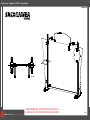
Classic Exhibits VK-1291 Setup Instructions
- Typ
- Setup Instructions

www.classicexhibits.com
Step 1
Page 1 of 2
866.652.2100
© 2010
WHEN DISASSEMBLING ALUMINUM EXTRUSION, TIGHTEN ALL
SETSCREWS AND LOCKS TO PREVENT LOSS DURING SHIPPING
Order #xxxxx - Sacagawea - VK-1291 - General Layout
Top View

www.classicexhibits.com
Step 2
Page 2 of 2
866.652.2100
© 2010
WHEN DISASSEMBLING ALUMINUM EXTRUSION, TIGHTEN ALL
SETSCREWS AND LOCKS TO PREVENT LOSS DURING SHIPPING
Order #xxxxx - Sacagawea - General Information
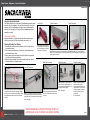
Using You Set-up Instructions:
The Visionary Designs Set-up Instructions for Sacagawea displays are created
specifically for your configuration. They are laid out sequentially, including an
exploded view of the entire display and a logical series of detailed steps for
assembly. We encourage you to study the instructions before attempting to
assemble your exhibit.
THIS IS VERY IMPORTANT!
Each page reminds you to tighten the setscrews after disassembling your
exhibit to prevent loss of the locks and setscrews (see below in red).
Cleaning & Packing Your Display:
1) Use care when cleaning aluminum extrusions or acrylic inserts. Use only
non-abrasive cleaners.
2) When cleaning laminate inserts or counter tops, use mild cleansers and
a soft material such as cotton.
3) Keep all display components away from extreme heat and long exposure
to sunlight to avoid warping and fading.
4) Retain all packing materials. It will make re-packing much easier and will
reduce the likelihood of shipping damage.
Hex Key Tool Typical Connection Typical Connection
Most visionary design exhibits can
be assembled with the supplied Hex
Key Tool. Occasionally, a flat head
screwdriver may be required. Detail A: Most horizontal extrusion connections have a patented expandable lock. This lock inserts into
the groove of an opposing extrusion. Tightening the lock with the Hex Key Tool expands the lock and creates
a strong positive connection.
Numbered
Label
Detail B: Each extrusion contains a numbered label that
corresponds to set-up instructions. The label is located
within a groove of the extrusion (when possible). Visionary
Design labels contain Black numbers unless otherwise
specified.
Horizontal Connection
Detail C: A rectangular connection bar with plastic
T Knobs is inserted between two horizontal extrusions
joined end-to-end. Turn the knobs clockwise to tighten.
Base Plate Connection Vertical Connection Corner Connection
Detail D: Attach vertical extrusions to base
plates with supplied bolts inserted through
the hole in the plate. Be careful not to strip
the thread.
Detail E: A square connection bar with
plastic T Knobs is inserted between two
vertical extrusions joined end-to-end. Turn
the knobs clockwise to tighten.
Detail F: Plastic Star Knobs are
used to tighten locks where
horizontal extrusions connect with
vertical extrusions. Turn the knobs
clockwise to tighten. Turn counter-
clockwise to loosen, but do not
remove knob.
Do Not Overtighten.
Do Not Overtighten.
Do Not Overtighten.

www.classicexhibits.com
Step 1
Page 1 of 2
866.652.2100
© 2010
WHEN DISASSEMBLING ALUMINUM EXTRUSION, TIGHTEN ALL
SETSCREWS AND LOCKS TO PREVENT LOSS DURING SHIPPING
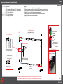
Order #xxxxx - Sacagawea - Backwall Assembly
Set upper horizontal bars
[5a/5b] to be flush with
top of vertical extrusions.
Horizontal Placement
2
5a
Item
1
2
3
4a/4b
5a/5b
6/6a
Description
Base Plate
42”h Square Vertical Extrusion w/ A10 Clamps Attached
42”h Square Vertical Extrusion w/ A10 Clamps Attached
27.5”w Horizontal Extrusion
27.5”w Horizontal Extrusion
2.5”h Angle-Cut Vertical
Qty.
2
1
1
1/1
1/1
1/1
Steps:
1) Attach vertical extrusions [2 and 3] to base plates [1].
2) Connect horizontal extrusions [4a to 4b and 5a to 5b] together using connection bars.
3) Attach horizontal assemblies [4a/4b and 5a/5b] between vertical extrusions as shown.
4) Attach A10 clamp to vertical extrusion [2] where indicated.
5) Attach angle-cut verticals to top of assembled backwall where indicated.
6) Apply graphic to back of assembled backwall.
1
1
Graphic Attachment
Apply graphic to back
of assembled backwall.
Connection
Bar w/ knobs
3
6a
Tighten setscrew
to secure
2.5” Vertical Attachment
Back View of Unit
5b
Insert connect into
groove of extrusion [3].
Tighten setscrew
to secure.
GREEN STAR indicates
location of connection
lock with knob.
2
3
4a 4b
5a 5b
6
6a
When desired location
is found, tighten
set screw to secure.
Tighten knob to
secure shelf in place.
Slide connector on back
of A10 clamp into groove
of extrusion.
A10 Clamp Attachment
*
**
*

www.classicexhibits.com
Step 2
Page 2 of 2
866.652.2100
© 2010
WHEN DISASSEMBLING ALUMINUM EXTRUSION, TIGHTEN ALL
SETSCREWS AND LOCKS TO PREVENT LOSS DURING SHIPPING
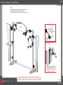
Order #xxxxx - Sacagawea - Accessory Attachment
W
i
n
g
W
i
n
g
Graphic
Cap
Standoff
Barrel
Slide connector on back of standoff
barrels into groove of extrusion
and twist to secure in place. Secure graphic
to standoffs using screw caps.
Graphic Attachment
Light Connection
Attach Lights to
Backwall where
desired and tighten
in place.
Header
Steps:
1) Attach header to upper horizontal bars using screwcaps.
2) Attach wing panels and plex shelf to A10 clamps.
3) Attach round sign to vertical where indicated using stand-offs.
Screwcap
Screwcap
Shelf

www.classicexhibits.com
866.652.2100
© 2010
WHEN DISASSEMBLING ALUMINUM EXTRUSION, TIGHTEN ALL
SETSCREWS AND LOCKS TO PREVENT LOSS DURING SHIPPING
Order #xxxxx - Case Packing Instruction
Base Plates
Horizontal bars #4a and 4b
Horizontal bars #5a and 5b
Header, wing panels and round sign
Vertical Extrusions 2 and 3
Plex Shelf
#6 and 6a
Lights
and
Setup Hardware
Level 1 (Bottom) Level 2 Level 3
Top View of each Level
Connection
Bars
-
 1
1
-
 2
2
-
 3
3
-
 4
4
-
 5
5


Classic Exhibits VK-1291 Setup Instructions
- Typ
- Setup Instructions
w innych językach
- English: Classic Exhibits VK-1291
Powiązane artykuły
-
Classic Exhibits VK-2964 Setup Instructions
-
-
-
-
-
-
-
-
-