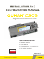
OUMAN C203 Deployment Manual
- Kategoria
- Pomiary, testowanie
- Typ
- Deployment Manual

www.ouman.
O1 Krzywa grzewczae
Types of heating systems:
• Radiator heating
• Floor heating
• Preregulation of air conditioning
• Hot water regulation
Regulation for three circuits
INSTALLATION AND
CONFIGURATION MANUAL
www.ouman. www.ouman.
Saving energy, creating comfort
XM1410B: Version 1.5.3->

2
Ouman C203 overview
This is the installation and configuration for C203. It describes configuration and set-up of the regulator,
customer-specific configuration as well as value settings.
The C203 is a heat regulator for three circuits that can be used to control two heating circuits and one hot
water circuit. Regulator can show in the display various usage modes depending on the connections and
configuration. You can navigate between functions by turning the C203’s selection knob. When you press the
selection knob (OK), you can view the details of specific functions.
Turn the control knob
to navigate in the menu.
Navigating between favourite views or returning to basic view
• The regulator has the Basic view for H1 circuit as default
• Users can save their views if they want.
Press the control button to
enter the menu.
Control knob and OK
Cancel button
Holding the key down for an extended
period of time returns the regulator to
its basic mode. The display shows the
basic view, the monitor dims and the
keyboard locks if the locking function
is in use.
OK OK
Pomiary
O1 Woda zasilająca
O2 Woda zasilająca
C.W.U. Sterowanie
>
>
>
>
Menu główne
How to acknowledge alarms: Press OK
and the alarm sound will stop. If the
reason for the alarm has not been corrected,
the exclamation point in the top right will
continue to blink.
Ouman C203 can generate alarms for several dierent reasons. In the
event of an alarm, an alarm window pops up showing detailed alarm
information and a beeping alarm signal goes on.
If there are several unacknowledged alarms, the latest activated
alarm is always shown in the display. As soon as all active alarms
have been acknowledged, the alarm window disappears and the
alarm signal goes o.
Alarm signal of all active alarms may also be muted by pressing Esc
button. When you press Esc, the alarm signal stops and the last alarm
windows disappear from the display.
You may look into the alarms later by going to ”Alarms” > ”Active
alarms”. If an alarm has not been acknowledged, an exclamation mark
will appear in the beginning of the row.
Alarm notice
O1 Alarm przegrzania
PR 1 GRUPA 1
O1 Woda zasilająca =10.2 °C
Odebrane: 08.11.2018 02:27
Naciśnij OK, aby potwierdzić alarm

3
Content
1 Connection instructions ......................................................................................................................................................4
2 Start up wizard (Uruchomienie kreatora) ..................................................................................................................... 7
3 Service(Serwis) ....................................................................................................................................................................... 8
3.1 Connections and configuration (Połączenia i konfiguracja ................................................................................................ 9
3.2 Service setting values (Ustawienia dla obiegu grzewczego) ...........................................................................................12
3.3 Restore factory settings, do backup and update device .....................................................................................................18
4 Favourite views ......................................................................................................................................................................19
Remote control option ................................................................................................................................................................21
Index ............................................................................................................................................................................................ 23
Technical information .............................................................................................................................................................. 24

4
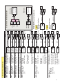
1 Connection instructions
*)
*)
*)
*)
*)
*)
4x0,8
4x0,8
24 VAC
24 VAC
24 VAC
0-10V
0-10V
4x0,8 24 VAC
0-10V
4x0,8
2x0,8
0-10V
11
22
33
44
55
66
77
88
99
10 10
11 11
12 12
13 13
14 14
15 15
16 16
17 17
18
41
30
42
43
44
45
46
47
48
49
50
51
52
53
54
55
56
18
VDC_Out
15V
5V
1
24 VAC IN
12 VDC IN
AO 6
AO 5
24 VAC
AO4
24 VAC
24 VAC
DI 2
UI 16
DI 1
UI 15
UI 14
UI 13
UI 12
UI 11
UI 10
UI 9
UI 8
UI 7
UI 6
UI 5
UI 4
UI 3
UI 2
UI 1
AO3
15 VDC (OUT)
C203
L
N
BG
A1
B1
TR1 (DO)
TR2 (DO)
AO1
24 VAC
AO2
Rele1 NC
Rele2 NC
C
C
NO
NO
Triac 1
Triac 2
230 V
50 Hz
125 mA
T
24 VAC
0-10 V ctrl
2x1.5
4x0.8
2x0,8
2x0,8
2x0,8
2x0,8
2x0,8
2x0,8
2x0,8
2x0,8
2x0,8
2x0,8
2x0,8
2x0,8
2x0,8
2x0,8
2x0,8
2x0,8
2x0,8
2x0,8
TMO
TMW/TMS
TMW/TMS
TMW/TMS
TMW/TMS
NO/NC or
pulse
Pulse
TMW/TMS
TMW/TMS
TMW/TMS
TMW/TMS
TMW/TMS
TMW/TMS
NO/NC
NO/NC
NO/NC
NO/NC
2
79
80
N
L
-
+
24 VAC
0-10 V ctrl
4x0.8
24
21
25
22
26
28
71
74
27
29
72
75
77
30
73
76
78
23
KL-LED
24VAC
24VAC
29
GSM modem data connection (RJ-45-2)
UI 1:Outdoor temperature sensor
UI 10: DH Supply water sensor or free meas.
UI 3: H1 Return water sensor
UI 2: H1 Supply water sensor
UI 11: DH Return water sensor or free meas.
UI 5: H2 Supply water sensor
UI 4: H1 DH Return water sensor
UI 12: H1 Pressure switch
UI 15: P2 Alarm (H1)
UI 16: Pump alarm, Pump indication
UI 6: H2 Return water sensor
UI 7: H2 DH Return water sensor
UI 13: H2 Pressure switch
UI 14: General compenstion or H/A switch
UI 9: HW Circulation/anticipate sensor
UI 8: HW Supply water sensor (Dom. hot w.)
DI 1: Pump alarm, Pump indication, General
alarm, Water ow meas. or Energy measurement
DI 2: Pump alarm, Pump indication, Water ow
meas. or Energy measurement
H2 Valve actuator 0 (2)...10 V
HW Valve actuator 0 (2)...10 V
cascade :
H2 Valve actuator 2
0 (2)...10 V
cascade:
HW Valve actuator 2
0 (2)...10 V
Bl
Red GSM-modem GSMMOD
power supply
Power
supply
Alternative connections are
shown on the next page.
Actuator’s combined
output power max. 15 VA
MicroSD memory card connection
External display connection
P3 Control (H2)
P2 Control (H1)
H1 Valve actuator
0 (2)...10 V
cascade:
H1 Valve actuator 2
0 (2)...10 V
NO = normal open (default)
NC = normal closed
Power supply
230VAC/125 mA
= Quick connection
front fuse max 10A
The sum alarm from the controller. Connect the external
power supply (12VAC - 230 VAC) to the indication lamp.
Below is an example of the connection.
Int. 24 VAC
ON
OFF
1
2
Use the slide switch to select either 15 Vdc (factory
setting) or 5 Vdc for the regulator’s output 52.
If an external power source is used with C203, move the
jumper from ON to OFF position (INT24Vax).
Pump connection (ver. 1.5.3->): If dual pump function is used, at least one pump must be connected NO type.

5
GSM modem data connection (RJ-45-2)
H1 Valve actuator
3-point controlled
H2 Valve actuator
3-point controlled
3-point controlled actuator
H2 Room temperature
sensor, TMR (more
information p.9)
H1 Room temperature
sensor, TMR (more
information p.9)
Primary connection Alternative connection
Home/Away-switch
H1 Pressure
transmitter,
0-20 mA or 0...10 V
H1 Pressure switch,
2-wire connection
H1 Pressure
transmitter,
2-wire connection
H2 Pressure
transmitter,
0-20 mA or 0...10 V
General compensation,
transmitter measure
General compensation,
Transmitter measure-
ment from separate
control unit.
H1 Pressure switch
(more information
p. 10)
H2 Pressure switch
(more information
p. 10)
General
compensation
(can be labelled,
more information
p. 10) 24 VAC, e.g strip
conn. 44
24 VAC, e.g strip
conn. 44
24 VAC e.g strip
conn. 44
strip
connector 52
strip connector 52
H2 Heat exchanger
DH Return water
sensor
H1 Heat exchanger
DH Return water
sensor
NO = normal open (default)
H1 Pressure transducer,
PX2.10B
cable 3m
cable 3m
H2 Pressure transducer,
PX2.10B
PX2.10B Pressure transducer
Black
Black
Blue
Blue
Brown
Brown
52
12
53
UI 12
UI 7
UI 10
UI 11
UI 4
2x0,8
2x0,8
C203
79
80
78
77
29
26
25
TR2 (DO)
TRS 2
TRS 1
Closed (24 VAC)
Closed (24 VAC)
Open (24 VAC)
Open (24 VAC)
4x0.8
4x0.8
4
7
7
7
4
7
UI 12
UI 13
UI 14
4x0,8
2x0,8
2x0,8
2x0,8
2x0,8
0-20mA/0-10V
0-20mA
15 VDC
24 VAC
12
12
12
10
11
12
12
13
13
14
14
14
4x0,8
2x0,8
0-20mA/0-10V
0-20mA
15 VDC
24 VAC
2x0,8
General measurement
Freely labelled
13
13
13
14
14
14
2x0,8
2x0,8
4x0,8
NO/NC
0-10V
0-10V
24 VAC
10
11
0.25-10.25V
0.25-10.25V
15-30 Vdc
15-30 Vdc
13
52
53
UI 13
24
TR1 (DO)
28
24 VAC
General measurement
Freely labelled
Alternative connections
General measurement
Freely labelled
DH Return water sensor
Freely labelled
General measurement
Freely labelled
DH Supply water sen-
sor (Freely labelled)
NTC10/ NTC1.8/
NTC2.2/NTC20/
NI1000/NI1000DIN/
PT1000 or 0-10 V
transmitter
NTC10/ NTC1.8/
NTC2.2/NTC20/
NI1000/NI1000DIN/
PT1000 or 0-10 V
transmitter
NTC10/ NTC1.8/
NTC2.2/NTC20/
NI1000/NI1000DIN/
PT1000
NTC10/ NTC1.8/
NTC2.2/NTC20/
NI1000/NI1000DIN/
PT1000
NTC10/ NTC1.8/
NTC2.2/NTC20/
NI1000/NI1000DIN/
PT1000
NTC10/ NTC1.8/
NTC2.2/NTC20/
NI1000/NI1000DIN/
PT1000

6
2x0,8
2x0,8
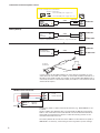
Twisted pair cable is used to connect RTU devices, e.g. DATAJAMAK 2 x (2 +
1) x 0.24.
The bus cable’s fault detector (FE) is connected to the BG connector of the
C203. In the master device the fault detector can be left disconnected or be
connected to a potential free contact. A 120 Ω terminating resistor is con-
nected to both ends of the bus.
The factory default for the device’s slave address is 10 and the bus speed is
9600 bauds. If necessary, make changes to the regulator’s system settings.
120 Ω
120 Ω
2x0,8
max. 5 A
24 VAC IN
12 VDC IN
12 VDC IN
BG
A1
A2
15 VDC OUT
15 VDC OUT
Battery backup:
GSM-modem connection:
Modbus RTU connection:
24 VAC ~
12 VDC -
-
-
+
+
+
52
52
23
55
53
53
22
56
54
54
21
OUMAN
GSMMOD
Bl
Red
C203
RJ45-2
GSMMOD
current feed
Master-
device
C203
Slave-device
BC
A1
B1
Data
Data
Requires separate 12 VDC UPS device, e.g. Ouman AP 1.
Int. 24 VAC
ON
OFF
38
37
Ouman
AP 1
Current supply for the GSM modem can come from the network via a net-
work device or from C203. The modem is connected to C203’s RJ45 Port 2. If
M-LINK is connected to C203, the modem is connected to M-LINK device’s C-
connector.(If Oulink is connected to C203, the modem is connected to Oulink
device’s RJ45-2 port.)
If an external power source is used with C203, move the jumper
from ON to OFF position (INT24Vax).
Connection of external power source:
Internal 24 VAC power supply in use
Internal 24 VAC power supply not in use
Explanation
Jumper
ON
OFF

7
Temp. zewnętrzna
O1 Woda zasilająca
O2 Woda zasilająca
C.W.U. Woda zasilająca
Automatyczny
Automatyczny
Automatyczny
19.4°C
19.2°C
19.8°C
58.0°C
13:51 12.04.2019 2
Wybór
Data
Pt 12.04.2019
dd.mm.yyyy
Wprowadź dzień
Czas
19:44
hh:mm
Wprowadź godzinę
Start-up wizard allows you to specify the regulator’s basic
settings. Accept the selection by pressing the selection knob
(OK). Change the selection by rotating the selection knob.
Set the date and press OK (the day of the week is updated automati-
cally).
Set the month and accept by pressing OK.
As final point set the year and accept by pressing OK.
When the circuit is taken into use, you must also select a heating met-
hod. Regulation curves and settings for various heating methods have
been pre-set at the factory and usually do not need to be changed.
Select a circuit-specific heating method:
Ogrzewanie podłogowe (Floor heating) is intended for normal floor
heating
Ogrzewanie grzejnikowe (Radiator heating): suited for a number
of new radiator-heated locations such as passive or energy ecient
houses.
Select the type of actuator.
H2 circuit configuration follows the same steps as H1 circuit configu-
ration.
If you select ”Yes”, the regulator will display the start-up sequence
when it is powered on. If you select ”No”, the regulator will display the
basic view when it is powered on. The heating method can then be set
in the circuit settings and service mode settings. Time and language
settings are found under system settings.
Czas (Time)
Data (Date)
H1 Circuit configuration
H2 Circuit configuration
Perform start-up sequence again?
Regulator basic mode
Next, set the time. Hours and minutes can be set separately.
Set hours and press OK to accept.
Set minutes and press OK to accept.
NOTE! If you later want to implement controlled start-up
again, select in the service mode ”Activate startup wizard.”
O1 Tryb ogrzewania
Wybór języka
Ogrzewanie podłogowe
Ogrzewanie grzejnikowe
Suomi/ Finnish
English
Svenska/Swedish
Eesti keel/ Estonian
Latvijas
Polish
Uruchomienie kreatora >
Zastosuj wybrane opcje, naciśnij OK
O1 Układ sterowania
O2 Układ sterowania
C.W.U. Układ sterowania
W użyciu English
Nieużywany
W użyciu
Nieużywany
W użyciu English
Nieużywany
When you take the circuit into use, you can select a voltage-controlled
motor type.
DHW Circuit configuration
Heating control of the main factors has been gathered to the home
screen of the controller. When the device is in sleep mode (button
has not been pressed for 10 minutes), the display shows the basic
display.
• A blinking exclamation mark indicates that the device is active
alarms.
• This number shows the number of active alarms.
Alarm notice
2 Start up wizard (Uruchomienie kreatora) OK

8
3 Service (Serwis)
Here is the C203 controller menu
structure. Press the control button
(OK) to enter the menu.
Service mode can be accessed with a
service code.
Enter the service code
and press OK.
Service mode shows the regulator’s
connections and is used to service
functions.
Regulator tuning is also done in ser-
vice mode and it includes all of the
regulator’s value settings.
Serwis
Połączenia i konguracja
Ustawienia dla obiegu grzewczego
Spadki temperatur
Funkcja opóźnienia ogrzewania grzejni-
kowego
Prognozowanie ogrzewania podłogowego
Tryb letni
Proces jesiennego osuszania
Kompensacja temperatury pokojowej
Pompad
Kompensacja temperatury powrotu wody
SC Kompensacja temperatury powrotu
wody
Ogólna kompensacja
Kompensacja magistrali
Pomiary magistrali
Ustawienie alarmu
Dostrajanie wartości
Przywróć ustawienia fabryczne
Przywracanie z kopii zapasowej
Utwórz kopię zapasową
Aktywacja kreatora uruchamiania
>
>
>
>
>
>
>
>
>
>
>
>
>
>
>
>
>
>
>
>
>
>
Turn the control knob to navigate in
the menu.
Press OK at the “Service” row.
Pomiary
Temperatura zewnętrzna -18.2 °C
----------------------------------------------------
O1 Woda zasilająca 35.1 °C
O1 Powrót wody 22.0 °C
>
>
>
>
O1 Układ sterowania
O2 Układ sterowania
Woda zasilająca
Informacja o temperaturze pokojowej
Pomiary
O1 Krzywa grzewcza
Ustawienie wartości
Tryb sterowania
Programy czasowe
Woda zasilająca
Informacja o temperaturze pokojowej
Pomiary
O2 Krzywa grzewcza
Ustawienie wartości
Tryb sterowania
Programy czasowe
>
>
>
>
>
Automatyczny
>
>
>
>
>
>
>
Automatyczny
>
>
C.W.U. Sterowanie
Ustawienie wartości
Tryb sterowania Automatyczny
Pomiary
Programy czasowe
>
>
>
>
Alarmy
Aktywne alarmy
Historia alarmów
Potwierdź wszystkie alarmy
Usuń historię alarmów
Harmonogram tygodniowy
Odbiorcy alarmów
>
>
>
>
>
>
2
Ustawienia systemowe
Czas 17:01
Data 12.04.2019
Czas letni W użyciu
Wybór języka
Polski
Ustawienia SMS
Ustawienia sieci
U s t a w i e n i a w y ś w i e t l a n i a
R o d z aj in f o r m a cj i
Kod blokady Nieużywany
>
>
>
>
>
>
>
>
>
Menu główne
Pomiary
O1 Układ sterowania
O2 Układ sterowania
C.W.U. Sterowanie
Alarmy
Ustawienia systemowe
Serwis

9
Check the functions on the screen that have been initialised.
X
Connection
place Alternative measurement options
W użyciu Note! Outdoor temperature can also read from bus.
W użyciu
W użyciu
Pomiar temperatury
O1 Pomiar temp. pokojowej
O1 Pomiar temp. pokojowej 0-10 V
O1 SC Powrót
W użyciu
W użyciu
Pomiar temperatury
O2 Pomiar temp. pokojowej
O2 Pomiar temp. pokojowej 0-10 V
O2 SC Powrót
W użyciu
W użyciu
Temperatura zewnętrzna
A1 Wody zasilającej
O1 Wody powrotnej
Pomiar 4
Temp. wody zasilającej
O2 Wody powrotnej
Pomiar 7
C.W.U. Ciepła woda użytkowa
C.W.U Cyrkulacja wody
Measurement More info
If the sensor is defective, the measurement value shown will be -50 or 130 °C.
Skalowanie wiadomości (Pomiar temp. pokojowej)
Min temperatura ____(0.0 °C)
Max temperature ____(50.0 °C)
Skalowanie wiadomości (Pomiar temp. pokojowej)
Min temperatura ____(0.0 °C)
Max temperature ____(50.0 °C)
Normalnie otwarty (NO)
Normalnie zamknięty (NC)
Normalnie otwarty (NO)
Normalnie zamknięty (NC)
Rodzaj wejść cyfrowych:
Rodzaj wejść cyfrowych:
General measurement settings
UI 10 Opóźnienie wejścia alarmowego ___(60 s)
UI 10 Priorytet alarmu ___ ((1 = Awaria (Emergency))
UI 10 Dolny próg alarmu ____(-51 °C)
UI 10 Górny próg alarmu ____(131 °C)
Switch alarm setting:
UI 10 Opóźnienie wejścia alarmowego ___(30 s)
UI 10 Priorytet alarmu ___ ((1 = Awaria (Emergency))
Switch alarm setting:
UI 11 Opóźnienie wejścia alarmowego ___(30 s)
UI 11 Priorytet alarmu ___ (1 = Awaria (Emergency))
General measurement settings
UI 11 Opóźnienie wejścia alarmowego ___(60 s)
UI 11 Priorytet alarmu ___ (1 = Awaria (Emergency))
UI 11 Dolny próg alarmu ____(-51 °C)
UI 11 Górny próg alarmu ____(131 °C)
Pomiar temperatury
Pomiar temperatury
Przełącznik alarmowy
Przełącznik alarmowy
→ Name: SC Temperatura wody zasilającej, other specify ______________
→ Name: SC Temperatura wody powrotnej, other specify ______________
→ Nazwa alarmu: Przełącznik alarmowy (UI10), other specify __________
→ Nazwa alarmu: Przełącznik alarmowy (UI10), other specify _________
Pomiar 10
Pomiar 11
UI1
UI 2
UI 3
UI 4
UI 5
UI 6
UI 7
UI 8
UI 9
UI 10
UI 11
3.1 Connections and configuration (Połączenia i konfiguracja)
Połączenia i konguracjaUI
UI1:Temperatura zewnętrzna
U I 2 : A 1 W o d y z a s i l a j ą c e j
UI3: O1 Wody powrotnej
UI 4: Pomiar 4
W użyciu >
>
Nieużywany >
Not in use >
If for example the measurement reads 0.5°C too much, set the
temperature correction to -0.5°C.
you can select type of temperature sensor NTC10,NTC1.8,
NTC2.2, NTC20, NI1000LG, NI1000DIN or PT1000
UI 1 : Temperatura zewnętrzna
Tryb pomiaru
Temp. zewnętrzna
Obraz trendu
Włącz dziennik trendu
Dziennik trendu – interwał próbkowania
Zapis dziennika trendu
Auto. zapis dziennika trendu
Ręczny
Wartość sterowania ręcznego
Regulacja pomiaru
Typ czujnika
W użyciu >
-2.4 °C >
>
Nie >
60 s >
>
Nieużywany>
Nie >
-50.0 °C>
0.0 °C>
NTC1 0 >
Usage connections are grouped according to connection points and
functions. When you press OK, a menu will open by the measurement/
connection point that you can use to:
read measurement information
You can take inputs/outputs into use
inspect connection point trends
change trend log settings
- The trend log can hold 2,000 measurement samples.
(if the sample interval is 60 seconds → log for 33 hours)
- The regulator produces a separate trend log for each measurement.
- The trend log is saved in a file (for example UI1.csv).
rename some of the connection points, see page 11.
operate a connection point manually
Obraz trendu 28.01 08:26:19 [ 34.7 °C ] (s )
38
28
Note! H1 Room temperature can also read from bus.
Note! H2 Room temperature can also read from bus.

10
ALARMS, INDICATIONS AND PULSE MEASUREMENTS
UI 15
UI 16
DI 1
DI 2
Alarm/
Wskazanie 15
Alarm/
Wskazanie 16
Wejście cyfrowe17
Wejście cyfrowe 18
Wskazanie→
Nazwa: P2.1 Pompy
P2 Alarm →
Priorytet alarmu ___ (1 = Awaria)
P3 Wskazanie →
Nazwa: P3 Pompy
P3 Alarm →
Priorytet alarmu ___ (1 = Awaria)
P1 Alarm→
Name: Pump 1 alarm
Alarm ogólny →
General alarm status
Priorytet alarmu ___ (1 = Awaria)
Pomiar przepływu wody
Pomiar energii
Pomiar przepływu wody
Pomiar energii
Skalowanie wejścia impulsowego:
Początkowy stan licznika
Nazwa pomiaru.:
Skalowanie wejścia impulsowego
Początkowy stan licznika
Nazwa pomiaru.:
_____ 10 l/pulse (1...100l/pulse)
______0.0 m3
DI1(2) Water flow measurement
_____ 10 kWh/pulse
(1...100 kWh/pulse)
______0.0 MWh
DI1(2) Pomiar energii
Normalnie otwarty
Normalnie zamknięty
Normalnie otwarty
Normalnie zamknięty
Normalnie otwarty
Normalnie zamknięty
Pomiar przepływu wody
Pulse measurement settings:
Pomiar energii
UI14 Pomiar 14 Ogólna kompensacja, 0-10 V
Ogólna kompensacja, 0-20 mA
Sterownie lokalne/zdalne
Pump indication can be selected when pump
control is also connected. The regulator emits a
conflict alarm if the regulator switches the pump
on but it does not activate. The alarm has a 5 s
delay.
Pump alarm: Pump indication data is supplied
by the frequency converter unit. The regulator
emits a pump alarm when a conflict state occurs.
When the counter initial value is set, go to the line “Za-
pisz wartość początkową licznika (Set initial value into the
counter)” and click “OK”.
Rodzaj wejścia cyfrowego:
Rodzaj wejścia cyfrowego:
Rodzaj wejścia cyfrowego:
Nazwa _________________
Nazwa _________________
Nazwa _________________
Nazwa _________________
Ogólna kompensacja (General compensation): In cir-
cuit-specific value settings you can specify the measurement
message range in which compensation is used, as well as the
maximum correction to supply water temperature that can be
made using compensation. You can assign names to general
compensation (e.g. solar compensation, wind compensation or
pressure compensation).
Przełączanie sterowania lokalnego/zdalnego (Home/ Away
control):
The control will be taken separately into use (see Service
mode→ Temperature drops). You can also do Home/Away control
in “Measurements”-menu or by SMS message (”Home”/”Away”), if a
GSM-modem is connected to the controller.
UI 13
UI12
Pomiar 13
Pomiar 12
Pomiar temperatury
Wyłącznik ciśnieniowy
Przetwornik ciśnienia V
Przetwornik ciśnienia mA
Pomiar temperatury
Wyłącznik ciśnieniowy
Przetwornik ciśnienia V
Przetwornik ciśnienia mA
Pressure transmitter measurement:
Pomiar ciśnienia: Automatyczny/Ręczny
Zakres pomiarowy ___(7.0 bar, setting range 0.0...25.0)
Nazwa pomiaru: (Pomiar ciśnienia 2) , other,
_________________________________,
Regulacja pomiaru:___0.00V, (-5.00...5.00)
Pomiar ciśnienia:
Ciśnienie 2 min limit _____ (0.5 bar (0.0...20.0)
Ciśnienie 2 max limit _____ (15.0 bar (0.0...20.0)
Pressure transmitter measurement:
Pomiar ciśnienia: Automatyczny/ Ręczny
Zakres pomiarowy ___(16.0 bar, setting range 0.0...25.0)
Nazwa pomiaru: (Pomiar ciśnienia 1) , other,
_________________________________,
Regulacja pomiaru:___0.00V, (-5.00...5.00)
Pomiar ciśnienia:
Ciśnienie 1 min limit _____ (0.5 bar (0.0...20.0)
Ciśnienie 1 max limit _____ (15.0 bar (0.0...20.0)
Wyłącznik ciśnieniowy:
Wyłącznik ciśnieniowy:
Normalnie otwarty
Normalnie zamknięty
Normalnie otwarty
Normalnie zamknięty
Rodzaj wejścia cyfrowego:
Rodzaj wejścia cyfrowego:
→Name: Meas. UI13; other _______________________________________
→ Name: Meas. UI12; other ______________________________________
Note
Alternative selectionsName
Input
P2.2 Wskazanie →
P2.2 Alarm →
P2.2 Wskazanie →
P2.2 Alarm →
P3.2 Wskazanie →
P3.2 Alarm →
P2.2 Wskazanie →
P2.2 Alarm →
P3.2 Wskazanie →
P3.2 Alarm →

11
Note
Alternative selectionsName
Input
AO1
AO1
TR1, TR2
AO3
AO3
TRS 1, TRS2
AO5
AO5
AO2
AO2
AO4
AO4
AO6
AO6
0-10 V / 2-10 V /
10-0 V / 10-2 V
3-punkty
0-10 V / 2-10 V /
10-0 V / 10-2 V
3-punkty
0-10 V / 2-10 V
10-0 V / 10-2 V
0-10 V / 2-10 V
10-0 V / 10-2 V
0-10 V / 2-10 V
10-0 V / 10-2 V
0-10 V / 2-10 V/
10-0 V / 10-2 V
AcSiłownik sterujący
O1 Siłownik sterujący
________________________
O2 Siłownik sterujący
________________________
C.W.U Siłownik sterujący
________________________
O1 Siłownik sterujący 2 (cascade)
________________________
O2 Siłownik sterujący 2 (cascade)
________________________
C.W.U Siłownik sterujący 2 (cascade)
________________________
Czas otwarcia siłownika ____ 150 s (10...500 s)
Czas zamknięcia siłownika ____ 150 s (10...500 s)
Czas otwarcia siłownika ____ 150 s (10...500 s)
Czas zamknięcia siłownika ____ 150 s (10...500 s)
Czas działania siłownika____ 15 s (10...500 s)
Czas działania siłownika ____ 150 s (10...500 s)
Czas działania siłownika ____ 150 s (10...500 s)
Czas działania siłownika ____ 15 s (10...500 s)
Nazwa
Potwierdź: Przytrzymaj OK
Anuluj: Przytrzymaj ESC
Ogól n a ko m sp ae cn
Renaming: Navigate to ”Measurement name” and press OK. A naming dialogue box will
open. Turn the selection knob and accept a letter by pressing OK.
Continue to the next screen by pressing OK.
Return to the previous screen by pressing ESC.
Accept the name by pressing OK for an extended period of time.
PUMP CONTROLS
Name Output Control mode Manual control
P2.1 Sterowanie
pompą (O1)
(72,73) zamknięte -> WŁĄCZONE/
(72,71) zamknięte -> WŁĄCZONE
Automatyczny
Ręczny →
Wył.
Wł.
P3.1Sterowanie pompą
(O2)
(75,76) zamknięte -> WŁĄCZONE/
(75,74) zamknięte -> WŁĄCZONE
Automatyczny
Ręczny →
Wył.
Wł.
P2.2 Sterowanie
pompą (O1)
(75,76) zamknięte -> WŁĄCZONE/
(75,74) zamknięte -> WŁĄCZONE/
TR1/ TR2/ TRS1 TRS2/
AO2/ AO4 / AO6
Automatyczny
Ręczny →
Wył.
Wł.
Funkcja podwójnej pompy::
Pompa rezerwowa
Pompa przemienna
P3.2 Sterowanie
pompą (O2)
(72,73) zamknięte -> WŁĄCZONE/
(72,71) zamknięte -> WŁĄCZONE/
TR1/ TR2/ TRS1 TRS2/
AO2/ AO4 / AO6
Automatyczny
Ręczny →
Wył.
Wł.
Funkcja podwójnej pompy:
Pompa rezerwowa
Pompa przemienna
SUM ALARM
TR 2
(connectors 79-80)
Sum alarm
(TRS 2)
Note! If a 3-point actuator
is in use in H2 control cir-
cuit, the sum alarm is not
in use.
1-kategoria
2-kategoria
1- lub 2-kategoria
An aggregate alarm is emitted if
an alarm in a selected alarm class
(priority) is activated.
Pompa rezerwowa, Backup pump/ Automatic: Backup pump/ Automatic: If pump 1 goes into a malfun-
ction the controller automatically switches on the backup pump (pump 2) and gives an alarm from pump 1.
Backup pump interval use: The controller drives the main pump (PX.1) once a week, on Mondays at 8.00-8.01 and the
backup pump (PX.2) 8.01-8.02. Backup pump function from version1.5.3.
Pompa przemienna , Alternate pump/ Automatic: Pumps 1 and 2 are controlled by the controller to function on al-
ternate time periods as a main pump. The other pump then functions as a backup pump. If pump goes into a malfun-
ction the controller automatically switches on the backup pump and gives an alarm from main pump. The pumps are
used alternatively so they both get the same amount of wear and thus have a longer lifespan.
The operation of the pumps is measured by a running time counter. The pump and the alternate pump vary by run
time and the pump change can be adjusted by the user (default 7 days, setting range 0...365 days). An alternative
pump function can be found from the version 1.53.
Interval operation also works in the alternating pump case. During interval operation, the co-pump is stopped, so only
one pump runs at a time.

12
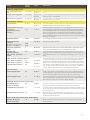
3.2 Heating curve settings (Ustawienia dla obiegu grzewczego)
Service mode includes all value settings for the regulator. Some of the value settings can also be found in the cir-
cuit’s “Value settings” menu. Value settings preceded by a -symbol are found only in service mode.
Changing a value setting: Select the desired value setting by turning the selection knob. Press OK. A new window
will open where changes can be made. Accept the changes by pressing OK. Exit change mode by pressing ESC.
The regulator shows H1 circuit regulation curve settings rst and then H2 circuit settings.
Both circuits have the same factory settings and setting ranges.
Ustawienia dla obiegu grzewczego
Setting Factory setting Range Explanation
Układ sterowania W użyciu Nieużywany/
W użyciu
Control circuits are already taken into use in start-up wizard. If you
want to have the control disabled, select “ Nieużywany (Not in use)”.
Tryb ogrzewania Ogrzewanie
grzejnikowe
Ogrzewanie
podłogowe/
Ogrzewanie
grzejnikowe
In the controller there are preset the typical heating curves for floor
heating and radiator heating. Also the factory settings are determined
by the heating type. If the radiator heating is selected, the controller
uses the outdoor temperature delay in supply water control (see
Radiator heating delay). If the floor heating is selected, the controller
uses outdoor temperature anticipate (see Floor heating anticipate).
Typ krzywej 5-punktowa
krzywa
3-punktowa
krzywa/
5-punktowa
krzywa
20 0 -20 °C
outd. t.
supply water
3
2
1
5
4
2
20 0 -20 °C
3
1
outd. t.
supply water
With the 3-point curve you can
change supply water tempera-
tures with the outdoor tempe-
rature values -20°C, 0°C and
+20°C.
With the 5-point curve you can
change the supply water set-
tings at fixed outdoor tempe-
rature -20°C and +20°C and at
three adjustable outdoor tem-
peratures (between -20 and
+20). To change the adjustable
outdoor temperatures press
OK for a long period of time.
Przesunięcie
równoległe
0.0 -15 ... +15 °C If room temperature is continuously above or below the setting
value despite the outdoor temperature, you can add a permanent
compensation value to the supply water setting value.
Tłumienie
przesunięcia równ.
7.0 -20 ... +20 °C Outdoor temperature set by the user at which the eect of
parallel shift begins to dampen. When the outdoor tempe-
rature reaches +20°C, the eect of parallel shift has already
completely stopped. The factory default setting for the dam-
ping point is 7°C. At a value setting of more than 17°C pa-
rallel shift damping is not enabled (the function is not avai-
lable if room temperature measurement is connected).
+ 60
+ 80
+ 40
+ 20
Parallel shift
Damping
point
Supply water °C
Outdoor t. -20 +20 0
Min.limit 18.0 °C 0 ... 99 °C The low limit for supply water. For comfort reasons, the higher low
limit is used in bath rooms than e.g. in rooms with parquet floor.
This also removes the moisture from path rooms at summer time.
Max.limit
Ogrzewanie
grzejnikowe/
Ogrzewanie
podłogowe
70 °C
45 °C
0 ... 99 °C High limit of supply water. With high limit settings it’s prevented
that there will not be too hot water in the circulation which might
damages the floor material of the heating pipes.
Kalibracja
siłownika
W użyciu Nieużywany/
W użyciu
The controller automatically calibrates the valve once a week on
(Monday at 09 am). The controller first completely closes the val-
ve and then opens to the position determined by the controller.

13
13
Setting Factory
setting Range Explanation
C.W.U. Układ sterowania Nieużywany W użyciu/
Nieużywany
The control circuits will be taken into use already in start up wizard.
If you want to have the control disabled, select “ Not in use”.
C.W.U. Nastawa temp. 58.0 °C 20 ... 90 °C DHW Supply water temperature setting.
C.W.U. Program czasowy Nieużywany W użyciu/
Nieużywany
Domestic hot water increases and drops can be made by DHW time
program. The change of temperature setting value is made either by
the week calendar or exception calendar.
C.W.U. Zmniejszenie tem-
peratury
10.0 °C 0 ... 30 °C The amount of drop in domestic hot water drop/increase time programs.
C.W.U. Zwiększenie tem-
peratury
10.0 °C 0 ... 30 °C The amount of increase in domestic hot water drop/increase time
programs.
Kalibracja siłownika W użyciu Nieużywany/
W użyciu
The controller automatically calibrates the valve once a week on
(Monday at 09 am). The controller first completely closes the valve
and then opens to the position determined by the controller.
Spadki temperatur
Spadek temperatury
Woda zasilająca, Ogrzewa-
nie grzejnikowe
Woda zasilająca, Ogrzewa-
nie podłogowe
Temperatura pokojowa
3.0
1.5
3.0
0... 40 °C Temperature drop of supply water, which be triggered from time pro-
gram or a Home/Away text message command or when selecting
continous temperature drop as circuit’s control mode. If room tempe-
rature measurement has been taken into use, the temperature drop
is given as a room temperature drop.
Duży spadek temperatury
Woda zasilająca, Ogrzewa-
nie grzejnikowe
Woda zasilająca, Ogrzewa-
nie podłogowe
Temperatura pokojowa
5.0
2.0
5.0
0... 40 °C A big temperature drop of supply water, which be triggered from time
program or a Home/Away text message command or when selec-
ting continous big temperature drop as circuit’s control mode. If room
temperature measurement has been taken into use, the temperature
drop is given as a room temperature drop.
Przegrzanie wody po
spadku
Ogrzewanie grzejnikowe/
Ogrzewanie podłogowe
Przegrzanie wody po
spadku
4.0
1.5
W użyciu
0... 25 °C
Nieużywany/
W użyciu
The amount of the automatic supply water pre-increase occurring
at the end of the temperature drop (time program) The pre-increase
helps raise the room temperature more quickly back to a nominal
room temperature after a temperature drop.
Room temperature can be increased to normal more quickly after
temperature drop by using the preliminary increase function.
Normal
temperature
Normal temperature
Pre-increase
Room temp.
°C
Time
Temperature drop period
Wstępne zwiększenie
czasu
1 0... 10 h The pre-increase time defines the time, when the pre-increase is
started. If pre-increase time is one hour, the pre-increase will start
one hour before the time program ends the temperature drop (retur-
ning to normal temperature).
Sterownie lokalne/zdalne W użyciu W użyciu/
Nieużywany
The Home/Away mode makes transitions between temperatu-
re levels. If transmission measurement is connected to the regula-
tor for general compensation, you cannot connect the Home/Away
switch but you can use the Home/Away mode via SMS or from the
regulator’s ”Measurements” menu.
Tryb wakacyjny Spadek temp. Spadek temp./
Duży spadek
temp.
If the Home/Away mode is in use, you can select the desired tempera-
ture in the ”Away” mode. The selections are temperature drop or big
temperature drop. The default is temperature drop.
Funkcja opóźnienia ogrz. grzejnikowego
Opóźnienie wpływu spad-
ku temp. zew.
Ogrzewanie grzejnikowe
2.0
0... 15 h Outdoor temperature delay is in use, if the radiator heating is se-
lected as a heating mode in the control circuit settings.
The amount of the outdoor temperature delay is defined with ”Outd.
temp.delay on temp.drop” setting. The delayed outdoor temperature is
used for regulating the supply water temperature. The typical outdoor
temperature delay for radiator heating is 2 hours. If the room tempe-
rature rises too much when temperatures lowers, increase the ”Outd.
temp.delay on temp.drop” If the opposite occurs, lower the delay time.
Opóźnienie wpływu wz-
rostu temp. zew.
Ogrzewanie grzejnikowe
2.0
0... 15 h Typically 2 hours delay time is used in radiator heating. If room tem-
perature decreases too much when outdoor temperatures increase
below the freezing point, increase the setting value ”Outd.temp.delay
on temp.increase.”

14
Setting Factory
setting Range Explanation
Prognozowanie ogrzewania podłogowego
Funkcja przewidywania spad-
ku temp.
Ogrzewanie podłogowe
2.0 0... 15 h The anticipation drop of floor heating is in use, if the the floor heating
is selected as a heating mode in the control circuit settings. Typically 2
hours delay time is used in floor heating. If room temperature falls too
much when freezing temperatures fall further, increase anticipation. If
the opposite occurs, lower anticipation.
Funkcja przewidywania wz-
rostu temp.
Ogrzewanie podłogowe
2.0 0... 15 h Anticipation of floor heating is used for stabilizing room temperature
when outdoor temperature changes. In floor heating, the concrete
mass of the floor slows transmission of heat from floor to room air tem-
perature. If room temperature rises too much when temperatures rises
in winter, increase anticipation.
Tryb letni
Pompa obiegowa W użyciu W użyciu/
Nieużywany
If C203 controls also the pump, the pump can be stopped while the
summer function mode is active.
Letni przestój 19.0 10 ... 35 °C Summer function outdoor temperature limit. When the measured or fore-
cast outdoor temperature exceeds the outdoor temperature limit of the
summer function, the regulation valve closes and the circulation water
pump stops as selected.
Czułość funkcji 6.0 -10...20 The summer function is turned o immediately if the real-time outdoor
temperature falls to the ”Summer function prevention limit.” The summer
function is also turned o if room temperature falls at least 0.5°C below
the value setting or when the regulator restarts.
Max. opóźnienie wył. funk-
cji lato
Wsp. opóźnienia wył. fun. lato
10
2.0
0...20h
0.5...3.0
The summer function switch o delay determines the starting time
for heating. This helps avoid unnecessary heating during summer in
case the outdoor temperature falls momentarily. The switch o delay
is calculated as follows: [the duration of the summer function] x [sum-
mer function o delayfactor] (limited to the set max delay value). The
switch o delay is reset if the room sensor is active and the room tem-
perature drops more than 0.5 °C below the set value, or in the event of
a power cut.
Prognozowanie temp. zew. Nieużywany W użyciu/
Nieużywany
In addition to measured outdoor temperature, temperature forecasts
from Foreca can be used with the summer function (requires Ounet
connectivity). If the regulator has not received outdoor temperature
forecasts via the data channel for 2 hours, the forecast is not used in
the summer function.
Wył. zaworu miesz. latem W użyciu W użyciu/
Nieużywany
The value setting is used to select whether or not the regulation valve
is closed when the summer function is in use.
Płukanie zaw. miesz. latem W użyciu W użyciu/
Nieużywany
The flushing operation is done in connection with inspection of the
valve’s position when the regulator is in summer function mode. During
the flushing operation the controller opens the valve to 20% and then
closes it. If the controller has stopped the pump, the controller runs the
pump during flushing of the valve. Valve flushing is done at 8:00 a.m.
on Mondays.
Proces jesiennego osuszania
Osuszanie jesienne W użyciu W użyciu/
Nieużywany
In autumn dry mode, supply water temperature is automatically raised
for 20 days. The function is turned on automatically when the avera-
ge daytime temperature has been more than 7°C for a minimum of 20
days and then falls below +7°C. The function remains on for the follo-
wing 20 days if the outdoor temperature is below 7°C (10 hour time
constant for measurement).
°C
v
at least 20 days
continuous period of more than +7 °C
7°C
Time /
24 hours
v
days with medium heat
Autumn dry function is active
(a total of 20 days)
Temperature limit of Autumn
dry activation
Wpływ na temp. wody zas.
Woda zasilająca, Ogrzewanie
grzejnikowe
Woda zasilająca, Ogrzewanie
podłogowe
Wpływ na temp. wew.
4.0
1.5
1.0
0... 25 °C
0 ... 15 °C
0.0... 1.5 °C
The value setting shows how much the autumn dry function raises
supply water temperature. If room temperature regulation is in use, the
user sets how much the room temperature is raised.

15
Setting Factory
setting Range Explanation
Kompensacja temperatury wewnętrznej
Kompensacja temp. wew. W użyciu W użyciu/
Nieużywany
It can defined whether room temperature aects to the con-
trol of supply water. If the measured room temperature dif-
fers from its setting
value, room compensation corrects the temperature of the
supply water.
Temperatura wewnętrzna 21.5 5... 50 °C Basic room temperature setting for the controller set by the
user. This setting value is not visible unless room compensa-
tion is in use.
Opóźnienie pomiaru temp.
wew.
2.0 0...2 h Amount of room temperature measurement delay (time cons-
tant). Dierent buildings react to temperature changes at
dierent rates. This setting value can reduce the eect of
the building on room regulation.
Współczynnik komp. temp.
wew.
Ogrzewanie grzejnikowe/
Ogrzewanie podłogowe
1.5
4.0
0...7 Coecient used in applying the dierence between room
measurement and the room setting value to the supply wa-
ter setting value. For example, if room temperature in ra-
diator heating is one degree below the setting value, supply
water is raised by four degrees.
O1 Max. wpływ komp. na
zasilanie
Ogrzewanie grzejnikowe/
Ogrzewanie podłogowe
5.0
16.0
0...25 °C Room compensation’s maximum eect on the supply water.
Kompensacja temp. wew.
Ogrzewanie grzejnikowe/
Ogrzewanie podłogowe
1.0
2.5
0.5 ... 7 h Time correction improves the room compensation function (I-
regulation). In massive houses or houses where floor heating
has been installed on a concrete floor, longer room compen-
sation correction times are used.
O1 Max. wpływ reg. na
wodę zasilającą
Ogrzewanie grzejnikowe/
Ogrzewanie podłogowe
3.0
2.0
0 ... 15 °C Room compensation time correction can change supply wa-
ter temperature to no more than this setting value. If room
temperature continuously fluctuates, check whether the
problem is resolved by lowering the setting value.
Pompad
Funkcja podwójnej pompy Pompa
rezer-
wowa
Pompa
przemienna/
Pompa
rezerwowa
The other pump can function either as an alternate pump or as a
backup pump. If you choose an alternate pump use, the pump
operates alternately as a main pump and a s a backup pump. The
backup pump starts when the main pump fails.
Okres czasu pracy pompy 7 dni 1...365 dni In alternate pump use the pumps 1 and 2 are controlled by the
controller to function on alternate time periods as a main pump and
a backup pump. The alternate use is aimed at constant pump wear
and a longer lifetime. The operation of the pumps is measured by a
run time counter.
Czas pracy pompy Information to be read from the pump running time counter.
Zresetuj licznik czasu pracy
pompy
Nie Nie/Tak It is good to reset the run time counter when replacing the old pump
with a new one.
Sterowanie pompą Automa-
tyczny
Automatyczny/
Ręczny
Pump control status: on / off. If necessary, you can force the pump
to manual control and select whether the pump is in on mode or in
off mode. If the control is set to manual, the palm image will appear
at the beginning of the line.
Kompensacja temperatury powrotu wody
Kompensacja temp. powrotu 2.0 0 ... 7.0 If return water temperature falls below the setting value for
danger of return water freezing, supply water temperature
is raised by the value: amount of the deficit multiplied by the
compensation ratio.

16
Setting Factory
setting
Range Explanation
SC Kompensacja temperatury powrotu wody
O1 (O2) SC Komp. temp.
wody pow.
W użyciu W użyciu/
Nieużywany
The function, which drops the setting value of heating circuit supply wa-
ter, if the DH return water temperature from the heat exchanger exceeds
the value of the compensation curve which is proportional to outdoor
temperature.
O1 (O2) SC Max. komp.
temp. wody pow.
20 0 ... 50 °C The value by which DH Return compensation can aect in maximum to
supply water setting.
O1 (O2) SC Komp. krzywej
temp. wody pow.
Enabled a 5-point curve, which can be edited.
H1 DH return temp. comp.
-20 = 65 °C
0 = 47 °C
+20 = 42 °C
Min.limit: 42 Max.limit: 65 +20 -200°C
20
40
60
80
-10 = 59 °C
+10 = 42 °C
Min. limit 42 20... 60 °C When DH return water temperature from heating exhanger is smaller
than min. limit, the eect of DH retur water compensation is zero.
Max.limit 65 50... 70 °C When DH return water temperature from heating exhanger is higher
than max limit, the eect of DH retur water compensation aects always.
O1 (O2) SC Nastawa pro-
porcjonalna P
200 2... 500 °C P-area of DH ret. water comp. in PI-control.
O1 (O2) SC Nastawa
całkująca I
180 0 ... 300 s I-time of DH ret. water comp. in PI-control.
Ogólna kompensacja
General compensation can increase or decrease the temperature of sup-
ply water. Transmitter measurement allows to utilize wind or solar mea-
surement or pressure dierential measurement over the heating network.
Przesunięcie równoległe
Kompensacja temp. powrotu
wody
0
100
0 ...100 %
0 ...100 %
Setting limit values for a compensation area. Set the transmitter mea-
surement message value at which compensation begins and the value at
which it reaches its maximum level. The amount of compensation is linear
between the limit values. (The transmitter is taken in use and setting val-
ues for the measurement area defined in the configuration of the particu-
lar measurement channel.)
Wpływ min. kompensacji 0-20 ... 20 °C Minimum compensation defines how much the supply water temperature
is changed when compensation begins.
Wpływ max. kompensacji 0-20 ... 20 °C Maximum compensation defines the maximum amount that compensa-
tion can raise or lower supply water temperature. If wind measurement is
used in transmitter measurement the setting value is positive, i.e. supply
water temperature is raised due to the wind. If solar measurement is used
in transmitter measurement the setting value is negative, i.e. supply wa-
ter temperature is lowered due to solar radiation.
°C
7
6
5
4
3
2
1
0
0 25 50 75 100
Compensation begins when the measurement message reaches 30%
Compensation is at its maximum when the
measurement message reaches 70%
Measurement message %
Maximum compensation
Raising supply water
temperature
Filtr kompensujący 5 0...300 s Output signal filtering. The filtering attenuates the eect of rapid chang-
es.
Kompensacja magistrali
In channel compensation the need for compensation can be specified by
an external device that relays the need for a supply water temperature
exception to the C203 through a communication channel (e.g. Ounet
S-compensation).
Max.wzrost temp.wody
zasilającej
00 ... 30.0 °C Channel compensation cannot increase supply water temperature more
than allowed by the setting value.
Max. spadek temp. wody zas. 00 ... 30.0 °C Channel compensation cannot drop supply water temperature more than
allowed by the setting value.

17
Setting Factory
setting
Range Explanation
Pomiary magistrali
Temp. zewnętrzna z magis-
trali
Nieużywany Nieużywany/
W użyciu
A outdoor temperature measurement can be read either from bus or through
UI1.
O1 Temp. wew. z magistrali Nieużywany Nieużywany/
W użyciu
A room temperature measurement specific to H1 control circuit can be read
either from bus or through UI4.
O2 Temp. wew. z magistrali Nieużywany Nieużywany/
W użyciu
A room temperature measurement specific to H2 control circuit can be read
either from bus or through UI7.
Ustawienie alarmu
Sygnał alarmowy W użyciu Nieużywany/
W użyciu
The alarm sound can choose to mute. The alarm is displayed in the active alarms
and forwarded even if the alarm sound is turned o.
O1 (O2) Ustawienia progów
alarmowych
Odchyłka alarmu wody
zasilającej
10.0
1...50 °C
Amount of dierence between measured supply water temperature and
the supply water temperature set by the regulator that causes an alarm
when the deviation has continued for the return delay time. A deviation
alarm is not allowed when heating has been turned o for the summer,
when the regulator is not on automatic or when outdoor temperature is
more than 10°C and supply water temperature is less than 35°C. The alarm
allows for a 5 s delay.
Opóźnienie alarmu 60min 0...120 min The alarm goes o if the deviation has lasted for the set time.
Alarm poziomu wody
zasilającej
Ogrzewanie grzejnikowe/
Ogrzewanie podłogowe
80.0
70.0
40...100 °C Supply water high limit alarm
Górny próg opóźnienia
alarmu
5 0...120 min A deviation alarm occurs when the value defined as the upper limit for supply
water alarm is exceeded for more than the delay time specified.
Nastawa temp.
antyzamrożeniowej
Powrót wody – opóźnienie
alarmu
8.0
5
5...25 °C
1...120 min
The return water freezing risk alarm is activated when return water
temperature has remained below the freezing risk limit for longer than
the allowed delay time. The exit delay for freezing risk alarm is 5 sec-
onds.
C.W.U. Kontrola: ustawienia alarmu:The controller gives a domestic hot water alarm when the temperature
of domestic hot water exceeds the preset overheating alarm limit or
falls below the low limit alarm limit and the excess/drop has lasted the
delay time of overheating/ low limit alarm. The exit delay of the alarms
is 5 minutes. If either DHW increase or drop is in use, the alarm limits
will change so that in increase/drop mode the alarm limit is always at
least 5 degrees above/below the current DHW setting value.
C.W.U. Górny próg alarmu
C.W.U. Dolny próg alarmu
C.W.U. Opóźnienie alarmu
68
40.0
10
65...120 °C
20...70 °C
0 ... 15 min
Pomiar ciśnienia
Ciśnienie 1(2) min limit 0.5 0...20 bar A lower limit alarm is activated when the pressure measurement de-
creases below the lower limit of the pressure measurement set value.
Alarm is deactivated when the pressure is 0.1 bar over the limit.
Ciśnienie 1(2) max limit 15 0 ... 20 bar The controller gives the upper limit alarm when the pressure measure-
ment is greater than the upper limit of the pressure set value. Alarm
goes o when the pressure is 0.1 bar below the limit.
UI 10 (UI11) Opóźnienie wejścia alarmowego
UI 10 (11) Opóźnienie
wejścia alarmowego
60 0...300 s An alarm is activated, when the measured temperature has been under
defined low limit or over high limit for longer than entry delay.
UI 10 (11) Dolny próg alarmu -51 -51...131 °C Low limit alarm is activated, when the temperature drops below the de-
fined low limit. The alarm is deactivated, when the temperature is 1.0 °C
over the lower limit.
UI 10 (11) Górny próg alarmu 131 -51...131 °C High limit alarm is activated, when the temperature increases above
the defined high limit. The alarm is deactivated when the temperature
is 1.0°C below the high limit.
Contact alarm of free measurements UI 10 and UI11
UI 10 (11) Opóźnienie
wejścia alarmowego
30 0...300 s Contact alarm is activated, when the entry delay has passed after an
alarm activation.

18
Dostrajanie wartości
O1 i O2 Dostrajanie wartości:
Nastawa P 200 2...600 °C Supply water temperature change at which the actuator runs the valve at
100%. E. g. If the supply water temperature changes 10 °C and the P area
is 200 °C the position of the actuator changes 5 % (10/200 x 100 % = 5 %).
Nastawa I 50 5 ... 300 s The deviation in the supply water temperature
from the set value is corrected by P amount in I time. For example, if deviation
is 10°C, P-range is 200°C and I time is 50 s, the actuator will be run at 5 %
for 50 seconds.
Nastawa D 00 ... 10 s Regulation reaction speed up in the event of a temperature change.
Beware of constant waver!
Max. szybkość zmian 4.0 0.5... 5°C/min The maximum speed at which the supply water can be raised when switching
from a temperature drop to a nominal temperature. If the radiators knock,
slow down the change rate (set the setting smaller).
Siłownik otwarty – czas pracy 150 10 ... 500 s The running time indicates how many seconds go by when the actuator
runs a valve nonstop from a closed position to an open position.
Siłownik zamkniety – czas
pracy
150 10 ... 500 s The running time indicates how many seconds go by when the actuator
runs a valve nonstop from a open position to an close position.
C.W.U. Dostrajanie wartości
Nastawa P 70 2 ... 500 °C Supply water temperature change at which the actuator runs the valve
at 100%.
Nastawa I 14 5 ... 300 s The deviation in the supply water temperature from the set value is
corrected by P amount in I time.
Nastawa D 0 0 ... 100 s Regulation reaction speed up in the event of a temperature change.
Beware of constant waver!
C.W.U. Prognozowanie 120 1....250 °C Uses anticipation sensor measurement information to speed up regula-
tion when DHW consumption changes. Increase the anticipation value
to decrease reaction to changes in consumption.
C.W.U. Szybkie uruchomienie 60 0 ... 100 % Functions during consumption changes. Decrease this value to de-
crease reaction to quick temperature changes.
Siłownik otwarty – czas pracy 15 10 ... 500 s The running time indicates how many seconds go by when the actuator
runs a valve nonstop from a closed position to an open position.
Siłownik zamkniety – czas pracy 15 10 ... 500 s The running time indicates how many seconds go by when the actuator
runs a valve nonstop from an open position to a close position.

19
Serwis
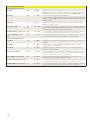
Przywróć ustawienia fabryczne >
Przywracanie z ko pii zapasowej >
Utwórz k opię zapas ową >
Aktywacja kreatora uruchamiania >
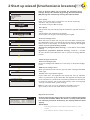
3.3 Restore factory settings and updates
Restore factory settings (Przywróć ustawienia fabryczne)
When you reset the system to factory default settings, the regulator will
revert to controlled start-up mode.
Create backup (Utwórz kopię zapasową)
Create a backup, when C203 has been configured and the device-
specific settings have been set.
If desired, also the factory settings can be restored to the device.
All the parameters which are saved in the non-volatile memory will
be included in the backup. Such parameters are e.g. all the setting
values and time programs. The backup can be saved to the internal
memory or to micro SD memory card. Memory card backups can be
copied from one device to another.
Technical requirements to microSD memory card:
• Standard: micro SDHC, UHS
• Capacity: 512 MB...32 GB,
• File system: FAT 32
• Class: 4...10+
Restore backup (Przywracanie z kopii zapasowej)
Przywracanie z kopii zapasowej
Z pamięci wewnętrznej >
Z karty pamięci >
If you created a backup, you can restore the backup by pressing OK.
You can restore the backup from the memory card or from the internal
memory.
Software updates
C203
memory card
t is recommended to create a backup of the system before software up-
date. The software update is done with following steps:
Insert microSD memory card which includes new software to controller
C203 asks: ”Would you like to restart device?”
Select: ”Yes”
C203 reboot to start the update of the new software. The updating of
the software takes few minutes.
Update external display firmware (Aktualizacja oprogramowania zewnętrznego)
C203
memory card
Insert the memory card containing the new firmware for the external dis-
play in the controller. Press OK.
Press OK- and ESC –buttons of the external display and connect the dis-
play to C203. The software update is started (the display flashes). The
update process takes few minutes.
Activate startup wizard (Aktywacja kreatora uruchamiania)
Start-up wizard allows you to specify the regulator’s basic settings. Ac-
cept the selection by pressing the selection knob (OK) (see page 7).

20
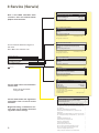
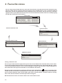
4 Favourite views
You can easily navigate from the basic view to the desired menu using the favourite view function. By tap-
ping the button you can navigate from one favourite view to another. There can be a maximum of five of
these views. The pre-installed favourite views show the circuits’ main menus. You can also save a particular
regulator view as your own favourite view. You can return from favourite views to the basic view by tapping
the ESC key until the basic view appears.
Get to set your own favorite displays when you exit the service mode of the controller back to basic mode.
If you want to immediately go from the service mode to the basic mode, press and hold the ESC key as long
as the control displays the main screen and the backlight is dimmed. (The controller automatically goes to
base mode, where the keys of the controller is not touched for 10 minutes.)
Navigate to the view you want to add to your favourite views. Hold down the key for an extended period
of time until the ”Save view in memory location:” menu opens. Use the dial to select the position where you
want to add the favourite view and press OK. If you select a location where a favourite view has already
been saved, the new favourite view will replace the existing one.
Note! Favorite the screens can not be stored in the service mode screens.
Setting a favourite view
Temp. zewnętrzna
O1 Woda zasilająca
O2 Woda zasilająca
C.W.U. Woda zasilająca
Automatyczny
Automatyczny
Automatyczny
19.4°C
19.2°C
19.8°C
58.0°C
13:51 29.06.2018 2
Wybór
Basic view
H2 Circuit menu
H1 Circuit menu
DHW Circuit menu
Your own favourite view
Your own favourite view
Historia alarmów
02.12.2016 10:11:42 Błąd czujnika O1: Woda z
05.12.2016 11:22:40 Błąd czujnika O1: Woda po
>
>
2
O1 Układ sterowania
O2 Układ sterowania
Woda zasilająca
Informacja o temperaturze pokojowej
Pomiary
O1 Krzywa grzewcza
Woda zasilająca
Informacja o temperaturze pokojowej
Pomiary
O2 Krzywa grzewcza
>
>
>
>
>
>
>
>
C.W.U. Sterowanie
Ustawienie wartości
Tryb sterowania Automatyczny
Pomiary
Programy czasowe
>
>
>
>
C.W.U. Sterowanie
Strona się ładuje...
Strona się ładuje...
Strona się ładuje...
Strona się ładuje...
-
 1
1
-
 2
2
-
 3
3
-
 4
4
-
 5
5
-
 6
6
-
 7
7
-
 8
8
-
 9
9
-
 10
10
-
 11
11
-
 12
12
-
 13
13
-
 14
14
-
 15
15
-
 16
16
-
 17
17
-
 18
18
-
 19
19
-
 20
20
-
 21
21
-
 22
22
-
 23
23
-
 24
24


OUMAN C203 Deployment Manual
- Kategoria
- Pomiary, testowanie
- Typ
- Deployment Manual
w innych językach
- English: OUMAN C203
Powiązane artykuły
Inne dokumenty
-
Grundfos IO 111 Installation And Operating Instructions Manual
-
 Hach POLYMETRON 8810 ISE Basic User Manual
-
 Hach POLYMETRON 8810 ISE Basic User Manual
-
 Hach Polymetron 9523sc pH Basic User Manual
-
 Hach POLYMETRON 8810 ORP Basic User Manual
-
-
Grundfos Conex DIA-1 Installation And Operating Instructions Manual
-
 Hach ORBISPHERE 510 Basic User Manual
-
Mettler Toledo 4000TOCe Sensor Instrukcja obsługi
-
 Hach ORBISPHERE 410 Basic User Manual


