
Voimatie 6 Tel. +358 424 8401
OUMAN OY FIN-90440 KEMPELE Fax +358 8 815 5060
www.ouman.fi FINLAND E-mail: ouman@ouman.fi
1/18
Modbus Connection for EH-100 Controllers
Configuration Guide
(Ver. 1.30, 24.01.2007)
Contents
1
2
3
3.1
3.2
3.3
3.4
Installation of the Modbus-100 communication card…………………………………………..2
Installation of Modbus 100-DIN unit to the EH-105
Modbus-100 card and Modbus-100-DIN adapter’s DIP switches configuration …….……2
MODBUS-100 device address (DIP 5-12) …..…..…………………………………………….2
MODBUS-100-DIN device address (DIP 5-12) .………………………………………….….2
Setting up biasing resistors (DIP 1-2) ….………………………………………………………3
Communication speed ……………………………………………………….…………….….…3
4
4.1
4.2
5
6
7
7.1
7.2
8
9
10
Modbus network cabling ……………………………………………………………………..…..3
MODBUS 100 Modbus network cabling …………………………………………………….....4
MODBUS 100-DIN, Modbus network cabling ……………………………………..………….4
EH-100 Modbus registers………………………………………………………………………...4
Special registers……………………………………………………………………………....…..5
Special registers…………………………………………………………………………………..5
Window registers………………………………………………………………………………….5
Mirrow registers ……………………………………………………………………………….…..5
Appendix 1: Individual addresses of the Modbus registers ………………………...………..7
Appendix 2: Alarm index………………………………………………………………………..17
Appendix 3: Index numbers for measurements and switches for Modbus registers
304-312 ………………………………………………………………………………………..…18

Voimatie 6 Tel. +358 424 8401
OUMAN OY FIN-90440 KEMPELE Fax +358 8 815 5060
www.ouman.fi FINLAND E-mail: ouman@ouman.fi
2/18
1 Installation of the Modbus communication card
Switch the power off before installing the Modbus card. Remove the plugs covering the screws on the controller enclosure.
Detach the covers from the enclosure, first the cover for the screw terminals (top) and then the larger cover (bottom).
Carefully rotate the lower cover 90 degrees so that the PCB at the bottom of the enclosure is visible. The controller display
unit fitted to the bottom cover is connected by flat cable to the PCB. Do not leave the bottom cover to hang from the flat
cable.
There is a microcircuit on a socket on close to the right edge of the PCB. The microcircuit code (N16 – EH-105 controller), is
printed on the PCB next to the microcircuit. Carefully detach the microcircuit from the socket.
Install the two plastic stand-offs that come with the Modbus card into the holes on the PCB. Align the Modbus card so that
the double row pin connector goes to the empty socket N16 and the plastic stand-offs on the main PCB fit into the holes in
the Modbus card. Press the Modbus card carefully into the place so that the pins go into the socket and the stand-offs will be
locked.
To use the Modbus interface, the DIP switches on the Modbus card must be configured correctly. The DIP switches can be
configured during the installation when the bottom cover is unattached or later with the covers in place. The display unit must
be detached from the bottom cover in order to configure DIP switches after refitting the bottom cover. The DIP switches are
then visible through the display unit opening and their position can be changed.
General communication parameters:
- Databits: 8
- Stop-bits: 1
- Paritity: No paritity
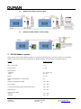
2 Installation of Modbus 100-DIN unit to the EH-105
Modbus-100-DIN must be installed to the
DIN rail next the EH-105. See the wiring
instructions page 4.
3 MODBUS-100 card and MODBUS-100-DIN DIP switches configuration
The DIP switch allows to configure the Modbus Device Address (1-247), the communication speed (4800, 960, 19200 or
38400 bits/s) and the biasing resistors for the bus.
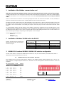
3.1 MODBUS-100 card, device address (DIP 5-12)
Each Modbus Device must have unique Device Address in the Modbus network. Allowed addresses are 1 to 247. The
Device Address is configured by DIP switches 5-12. DIP switch 5 is the least significant bit and DIP switch 12 is the most
significant.
DIP switch position, 1 = ON Address
DIP 5 DIP 12
1 0 0 0 0 0 0 0 = 1
0 1 0 0 0 0 0 0 = 2
1 1 0 0 0 0 0 0 = 3
0 0 1 0 0 0 0 0 = 4
1 0 1 0 0 0 0 0 = 5
0 1 1 0 0 0 0 0 = 6
1 1 1 0 0 0 0 0 = 7
………………………………………
1 1 1 0 1 1 1 1 = 247
Modbus-100-DIN
strip connector
Description
EH-105 connection
┴
24 VAC GND and signal gnd
Strip connector ┴
~
24 VAC ~
Strip connector 41
A
RS-232 RX
Strip connector A
C
RS-232 TX
Strip connector C
Biasing
resistors
Comm
unicati
on
speed
Device address

Voimatie 6 Tel. +358 424 8401
OUMAN OY FIN-90440 KEMPELE Fax +358 8 815 5060
www.ouman.fi FINLAND E-mail: ouman@ouman.fi
3/18
3.2 MODBUS-100-DIN, device address (5-9)
Each Modbus Device must have unique Device Address in the Modbus network. Allowed addresses are 1 to 31. The Device
Address is configured by DIP switches 5-9. DIP switch 5 is the least significant bit and DIP switch 9 is the most significant.
DIP switch position, 1 = ON Address
DIP 5 DIP 9
1 0 0 0 0 = 1
0 1 0 0 0 = 2
1 1 0 0 0 = 3
0 0 1 0 0 = 4
1 0 1 0 0 = 5
…………………
1 1 1 1 1 = 31
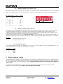
3.3 Setting up biasing resistors (DIP 1-2)
The Modbus-100 card and Modbus-100-DIN uses galvanically isolated RS-485 driver. Only one device at a time can write
into the network, while other devices are listening. For this reason there are situations when no device writes into the
network but all of them are listening. The biasing resistors ensure that the network reamains stable in this situation. This is
especially important if the network is long and if there is external interference.
Biasing resistor must be taken into use in two (and only two) devices per network, one at each end of the network. The
biasing resistors are taken into use using the Modbus-100 card’s or Modbus-100-DIN adapters DIP switches 1-2 as follows:
DIP1 DIP2
0 0 Biasing resistors are not in use
1 1 Biasing resistors are in use
3.4 Communication speed
The communication speed must be configured to be same for all of the devices on the same Modbus bus. The
communications speed is configured via bit switches 3-4 as follows:
:DIP4 DIP3 Speed
0 0 4800
0 1 9600
1 0 19200
1 1 38400
4 Modbus network cabling
A shielded twisted pair cabling is used for networking e.g. Belden 8762 or Datajamak 2x(2+1)x0.24. The network must be
wired as a daisy-chain, the cable going from one device to the next and there must not be any stubs (max. length of stub 0.5
m). The maximum length of the whole network is 1200m. 120 Ohm terminating resistors are connected to the both ends
of the network.
The protective shield of the twisted pair cable can be connected if needed in to protective earth in order to eliminate
interference. The connection is made only on one end of the protective shield.
Biasing
resistors
Bus
speed
Device address

Voimatie 6 Tel. +358 424 8401
OUMAN OY FIN-90440 KEMPELE Fax +358 8 815 5060
www.ouman.fi FINLAND E-mail: ouman@ouman.fi
4/18
4.1 MODBUS-100 Modbus network cabling
4.2 MODBUS-100-DIN Modbus network cabling
5 EH-100 Modbus registers
Data in the EH-100 controllers Modbus registers is arranged so that information in the same context is in consecutive
registers. This makes it easier to read data from the Modbus network. The information is arranged as follows:
Context Modbus registers
Time 0 – 3
AHU control mode 4 – 5
Time programs 6 – 48
Measurements
- analogue 51 – 79, 82 – 87
- digital 80 – 81
Alarms 90 – 97
Alarm acknowledgement, category bits 98
reset
Network measurements writing 100 – 105
User settings 111 – 133
Control loops operating mode and manual control 138 – 139
Supply air info 140 – 167
Service level settings
- general 170 – 196
- damper 197 – 215

Voimatie 6 Tel. +358 424 8401
OUMAN OY FIN-90440 KEMPELE Fax +358 8 815 5060
www.ouman.fi FINLAND E-mail: ouman@ouman.fi
5/18
- heat recovery 216 – 234
- heating 235 – 252
- cooling 253 – 271
- AHU operation 272 – 298
- alarms 299
- temperature control 300
- 24Vac on/off outputs 301 – 303
- measurements and digital inputs 304 – 318
- transmitter ranges 319 – 332
- transmitter types 333 – 338
Controller text fields, read/write 339 – 354
Controller operating code 355 – 369
Individual register addresses and corresponding controller information are available in Appendix 1.
6 Using Modbus registers
When the controller starts up the Modbus card updates the contents of its registers from the controller so it does not answer
questions. Updating of the registers takes about 13 seconds. EH-105 controllers have as a standard a local user interface
from which settings can be adjusted. For this reason, there is a risk that the data in monitoring program (PC) is not up-to-
date with the actual controller data.
To prevent this from occurring, registers that contain the controller's setting type variables are divided into categories N1-N7.
If a setting is changed locally, this information is sent to register 81, bits 9-15. By monitoring bits 9-15 in register 81, the
monitoring program knows if the settings have been changed locally and can update the settings on the PC end. The
register's categories are listed in appendix 1. After updating, the front-end can reset register 81's bits 9-15 by writing the
value OxFE in register 98. Register 400 shows whether updating between the controller and Modbus card of
registers belonging to categories N1-N7 is occuring. If the value of register 400 is 0xFF, updating is occuring and an
application with a Modbus interface should not read category N1-N7 registers but waits for the value of register 400 to return
to zero.
When controllers time programs are manipulated from the local user interface (changed or just checked) and after that when
the user exits, the controller rearranges the time programs. For this reason the time programs states may no longer be in the
same Modbus registers that they originally were in. Nevertheless the controller always sets category bit N1 (time programs),
so the PC must always read the time programs again when this bit has been set. Empty spaces cannot be left in the time
program registers, but they must be filled in order.
Alarms are coded as bit data in registers 90-95. Alarm index is listed in Appendix 2. Bit data is saved during power failures
so it is always up-to-date. The alarm is acknowledged by writing active alarm index number to the register 98. This will
silence the alarm buzzer, but the alarm is still displayed in registers 90-95 until the alarm situation is normalized.
7 Special registers
7.1 Window registers
The EH-100 controller Modbus interface makes it possible to inspect and change the entire register space in 16 register
packages. This means that only 17 registers are needed to manage one controller, e.g., in a monitor application. To do this
use registers 500 – 516. Enter the address of the first register of the window you want to examine into register 500. Then
this address and the following 15 register values can be read from registers 501 – 516.
Example: Read registers 111 – 126 using window registers.
1. Enter number 111 into (register 1. of the window register) register 500.
2. After this register 111-126 values can be processed through registers 501 – 516.
7.2 Mirrow registers
The EH-100 controller modbus interface has setting registers whose upper and lower bits have different settings. For
example, when changing a lower bit setting, you must be careful that you do not accidently change the upper bit setting. In
addition, the above mentioned procedure may cause problems with some monitoring programs.
To minimize this problem, MODBUS – 100 the interface have so called mirror registers. The same Modbus operations (read
and write) that are carried out with the standard registers can be carried out with the mirror registers. Their register
addresses and content are as follows:
- 2000 – 2354: register’s upper bits 0 – 354 (MSB)
- 4000 – 4354: register’s lower bits 0 – 354 (LSB)
- 6000 – 6709: the original register is divided into MSB:s and LSB:s as follows:
o 6000 = 0 MSB, 6001 = 0 LSB, 6002 = 1 MSB, 6003 = 2 LSB…6708=354 MSB, 6709 = 354 LSB

Voimatie 6 Tel. +358 424 8401
OUMAN OY FIN-90440 KEMPELE Fax +358 8 815 5060
www.ouman.fi FINLAND E-mail: ouman@ouman.fi
6/18
Example:
Register 113 MSB: Maximum supply air temperature.
Register 113 LSB: Minimum supply air temperature.
Read and change only the “Max supply air temperature.” value by processing register 2113
Read and change only the “Maximum supply air temperature.” value by processing register 4113
Or
Read and change only the “Maximum supply air temperature.” value by processing register 6226
Read and change only the “Minimum supply air temperature.” value by processing register 6227

Voimatie 6 Tel. +358 424 8401
OUMAN OY FIN-90440 KEMPELE Fax +358 8 815 5060
www.ouman.fi FINLAND E-mail: ouman@ouman.fi
7/18
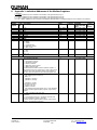
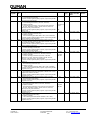
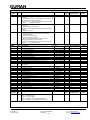
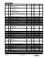
8 Appendix 1: Individual Addresses of the Modbus Registers
Categories:
P1 = data is updated from the controller to the Modbus Card approximately every 7s
P2 = data is updated from the controller to the Modbus Card approximately every 30s
P3 = data is updated from the controller to the Modbus Card approximately every 60s
N1 – N7 = data is updated from the controller to the Modbus card whenever it is changed locally from the controller’s user interface
Time:
Modbus
register
Byte/
Bit
Description
Limits
Category
Supperted
Modbus Function
Codes
Control-
ler
Version
0
Year
2000…2099
P3
03 (r), 06(w), 16(w)
1
MSB
Month
1…12
P3
03 (r), 06(w), 16(w)
1
LSB
Day
1…31
P3
03 (r), 06(w), 16(w)
2
MSB
Hour
0…23
P3
03 (r), 06(w), 16(w)
2
LSB
Minute
0…59
P3
03 (r), 06(w), 16(w)
3
MSB
Second
0…59
P3
03 (r), 06(w), 16(w)
3
LSB
Weekday, 0= Sunday
0…6
N5
03 (r), 06(w), 16(w)
AHU Control Mode :
4
MSB
AHU Control Mode
0 = AUTO
1 = TIMED
2 = CONTINUOUS
3 = SERVICE (STOP)
4 = BUS (STOP)
0…4
P1
03 (r), 06(w), 16(w)
1.21 ->
4
LSB
AHU Output Speed:
0 = OFF
50 = 1/2
100 = 1/1
0,50,100
P1
03 (r), 06(w), 16(w)
1.21 ->
5
Countdown Timer
0…599
P1
03 (r), 06(w), 16(w)
1.21 ->
Time Programs:
6
Time Program Selection:
0 = Week Program
1 = Special Day Program
2 = Exception Calendar
3 = B-alarms Enable
4 = Night drop Time Program
5 = Night Cooling Enable
NOTE! When the Modbus interface updates registers 7-
48 from the device, this register has a value of 0xFF. Wait
until the value 0xFF disappears before using registers 7-
48. The same information can be read from register 400.
0…5
-
03 (r), 06(w), 16(w)
7
Week Program:
First switching point week days
Bits 0…8:
00000001 = monday
00000010 = tuesday
…
01000000 = sunday
Special Day Program:
register not in use
Exception Calendar:
First switching point date (MSB = DAY, LSB = MONTH)
B alarms enable, night drop time program, night cooling
enable:
”ON”- switching point week days
0…0x7F
N1
03 (r), 06(w), 16(w)
8
MSB
Week Program, Special Day Program,Exception
Calendar:
First switching point hours. (Exception calendar does
not use register if its status is 246-253).
B alarms enable, night drop time program, night cooling
enable: ON switching point hours
0…23
N1
03 (r), 06(w), 16(w)

Voimatie 6 Tel. +358 424 8401
OUMAN OY FIN-90440 KEMPELE Fax +358 8 815 5060
www.ouman.fi FINLAND E-mail: ouman@ouman.fi
8/18
Time Programs cont…
Modbus
Register
Byte/
Bit
Description
Limits
Cate
gory
Supported
Modbus Function
Codes
Controller
Version
8
LSB
Week Program, Special Day Program,Exception Calendar:
First switching point minutes.
B alarms enable, night drop time program, night cooling enable:
ON switching point minutes.
0…59
N1
03 (r), 06(w), 16(w)
9
Week Program, Special Day Program:
First switching point status (0, 50=min, 100=max)
Exception Calendar:
First switching point status (0,50=min,100=max,246=mon,
247=tue, 248=wed, 249=thu, 250=fri, 251=sat, 252=sun,
253=special day, 254=automatic)
B alarms enable, night drop time program, night cooling enable:
Always 100
0,50,100
0,50,100,24
6-254
100
N1
03 (r), 06(w), 16(w)
10
Week Program:
Second switching point week days
Exception Calendar
Second switching point date (MSB = DAY, LSB = MONTH)
B alarms enable, night drop time program, night cooling enable:
”OFF” switching point week days
0…0x7F
N1
03 (r), 06(w), 16(w)
11
MSB
Week Program, Special Day Program,Exception Calendar:
Second switching point hours (Exception calendar does not
use register if its status is 246-253).
B alarms enable, night drop time program, night cooling enable:
”OFF” switching point hours
0…23
N1
03 (r), 06(w), 16(w)
11
LSB
Week Program, Special Day Program,Exception Calendar:
Second switching point minutes
B alarms enable, night drop time program, night cooling enable:
”OFF” switching point minutes
0…59
N1
03 (r), 06(w), 16(w)
12
Week Program, Special Day Program:
Second switching point status (0, 50=min, 100=max)
Exception Calendar:
Second switching point status (0,50=min, 100=max,
246=mon, 247=tue, 248=wed, 249=thu, 250=fri, 251=sat,
252=sun, 253=special day, 254=automatic)
B alarms enable, night drop time program, night cooling enable:
Always 0
0,50,100
0,50,100,
246-254
0
N1
03 (r), 06(w), 16(w)
13
Week Program:
Third switching point week days
Exception Calendar
Third switching point date (MSB = DAY, LSB = MONTH)
B alarms enable, night drop time program, night cooling enable:
Register not in use
0…0x7F
N1
03 (r), 06(w), 16(w)
14
MSB
Week Program, Special Day Program,Exception Calendar:
Third switching point hours (Exception calendar does not use
register if its status is 246-253).
B alarms enable, night drop time program, night cooling enable:
Register not in use
0…23
N1
03 (r), 06(w), 16(w)
14
LSB
Week Program, Special Day Program,Exception Calendar:
Third switching point minutes
B alarms enable, night drop time program, night cooling enable:
Register not in use
0…59
N1
03 (r), 06(w), 16(w)
15
Week Program, Special Day Program:
Third switching point status (0, 50=min, 100=max)
Exception Calendar:
Third switching point status (0,50=min,100=max,246=mon,
247=tue, 248=wed, 249=thu, 250=fri, 251=sat, 252=sun,
253=special day,254=automatic)
B alarms enable, night drop time program, night cooling enable:
Register not in use
0,50,100
0,50,100,
246-254
N1
03 (r), 06(w), 16(w)
46
Week Program:
Last switching point week days
Exception Calendar:
Last switching point date (MSB = MONTH, LSB = DAY)
B alarms enable, night drop time program, night cooling enable:
Register not in use
N1
03 (r), 06(w), 16(w)

Voimatie 6 Tel. +358 424 8401
OUMAN OY FIN-90440 KEMPELE Fax +358 8 815 5060
www.ouman.fi FINLAND E-mail: ouman@ouman.fi
9/18
Time Programs cont…
Modbus
Register
Byte/
Bit
Description
Limits
Cate-
gory
Supperted Modbus
Function Codes
Controller
Version
47
MSB
Week Program, Special Day Program,Exception
Calendar:
Last switching point hours (Exception calendar does not
use register if its status is 246-253).
B alarms enable, night drop time program, night cooling
enable: Register not in use
0…23
N1
03 (r), 06(w), 16(w)
47
LSB
Week Program, Special Day Program,Exception
Calendar:
Last switching point minutes
B alarms enable, night drop time program, night cooling
enable:
Register not in use
0…59
N1
03 (r), 06(w), 16(w)
48
Week Program, Special Day Program:
Last switching point status (0, 50=min, 100=max)
Exception Calendar:
Last switching point status
(0,50=min,100=max,246=mon,
247=tue, 248=wed, 249=thu, 250=fri, 251=sat,
252=sun, 253=special day,254=auto)
B alarms enable, night drop time program, night cooling
enable: Register not in use
0,50,100
N1
03 (r), 06(w), 16(w)
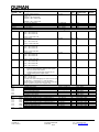
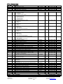
Measurements:
Modbus
Register
Byte/
Bit
Description
Limits
Cate-
gory
Supported Modbus
Function Codes
Controller
Version
51
Room air humidity
0…100 [%]
P3
03 (r)
52
Supply air temperature
-30.00…100.00 [°C]
P2
03 (r)
53
Exhaust air temperature
-30.00…100.00 [°C]
P3
03 (r)
54
Heating coil return water temperature
-30.00…100.00 [°C]
P2
03 (r)
55
Room temperature 2
-30.00…100.00 [°C]
P2
03 (r)
56
Outdoor temperature
-50.00…100.00 [°C]
P3
03 (r)
57
Supply air temperature 2
-30.00…100.00 [°C]
P2
03 (r)
58
Room temperature
-30.00…100.00 [°C]
P3
03 (r)
59
HRU Frost Protection Temperature
-30.00…100.00 [°C]
P3
03 (r)
60
Supply air temperature after heat recovery unit
-30.00…100.00 [°C]
P3
03 (r)
61
External setpoint potentiometer
-5.00…4.00 [°C]
P3
03 (r)
62
Free temperature measurement channel (user defined
description)
-30.00…100.00 [°C]
P3
03 (r)
63
Supply air pressure
0…999 [Pa]
P2
03 (r)
64
Exhaust air pressure
0…999 [Pa]
P2
03 (r)
65
CO2 content
0…2000 [ppm]
P3
03 (r)
66
Supply air flow
0.0…10.0 [m/s]
P2
03 (r)
67
Exhaust air flow
0.0…10.0 [m/s]
P2
03 (r)
68
Supply air filter differential pressure
0…999 [Pa]
P3
03 (r)
69
Exhaust air filter differential pressure
0…999 [Pa]
P3
03 (r)
70
HRU differential pressure
0…999 [Pa]
P3
03 (r)
71
HRU efficiency
0…100 [%]
P3
03 (r)
72
Damper output
0…100 [%]
P2
03 (r)
73
Heat Recovery Unit output
0…100 [%]
P2
03 (r)
74
Heating output
0…100 [%]
P2
03 (r)
75
Cooling output
0…100 [%]
P2
03 (r)
76
AHU control
0…100 [%]
P2
03 (r)
77
Supply fan speed
0…100 [%]
P2
03 (r)
78
Exhaust fan speed
0…100 [%]
P2
03 (r)
79
AHU running hours
0…999 [h]
P3
03 (r)
I/O Status:
Modbus
Register
Byte/
Bit
Description
Limits
Cate-
gory
Supperted Modbus
Function Codes
Controller
Version
80
Bit 0…6: Digital inputs
Bit 7…9: Relay outputs
Bit 10…12: 24V outputs
Bit 13: AHU 230V running information status
Bit 14: Controller`s run command for AHU status
0…FFh
P1
03 (r)

Voimatie 6 Tel. +358 424 8401
OUMAN OY FIN-90440 KEMPELE Fax +358 8 815 5060
www.ouman.fi FINLAND E-mail: ouman@ouman.fi
10/18
Category Polling Requests:
Modbus
Register
Byte/
Bit
Description
Limits
Cate-
gory
Supported Modbus
Function Codes
Controller
Version
81
Category polling requests
Bits 9…15
0000001 = N1-request ON
0000010 = N2 - request ON
…
1000000 = N7 - request ON
0…FFh
P1
03 (r)
82
SF pressure difference
0…5000 [Pa]
P3
03 (r)
83
EF pressure difference
0…5000 [Pa]
P3
03 (r)
84 ja 85
SF air volume
0.0… [m3/s]
P3
03 (r)
86 ja 87
EF air volume
0.0… [m3/s]
P3
03 (r)
Alarms: Note! Look relevant alarm index information from appendix 2.
90
Alarm Status
Bit 0 = alarm index 117
Bit 1 = alarm index 118
…
Bit 15 = alarm index 132
0…FFh
N2
03 (r)
91
Alarm Status
Bit 0 = alarm index 101
Bit 1 = alarm index 102
…
Bit 15 = alarm index 116
0…FFh
N2
03(r)
92
Alarm Status
Bit 0 = alarm index 149
Bit 1 = alarm index 150
…
Bit 15 = alarm index 164
0…FFh
N2
03(r)
93
Alarm Status
Bit 0 = alarm index 133
Bit 1 = alarm index 134
…
Bit 15 = alarm index 148
0…FFh
N2
03(r)
95
Alarm Status
Bit 0 = alarm index 165
Bit 1 = alarm index 166
…
Bit 6 = alarm index 171
0…FFh
N2
03(r)
98
Alarm Acknowledgement
- Alarm is acknowledged by writing to this register
the active alarm index number
- Category polling request flags (register 81) are
reset by writing to this register 0xFE
0…FFh
-
03 (r), 06(w)
99
Sum alarm
Bit 0 = A-sum alarm
Bit 1 = B-sum alarm
Function: If an alarm belonging to an alarm class is active
the bit state is 1, otherwise it is 0. If the bit state is
already 1 when a new alarm occurs, it goes to 0 for about
20 sec. and then it returns to its original state.
03 (r)
Bus measurement inputs:
100
Outdoor temperature
-50.00…100.00 [°C]
-
06(w), 16(w)
101
Room temperature
-30.00…100.00 [°C]
-
06(w), 16(w)
102
CO2-content
0…2000 [ppm]
-
06(w), 16(w)
103
Main pump running status
-
06(w), 16(w)
104
Heating network`s water pressure switch
-
06(w), 16(w)
105
Emergency stop, supply
-
06(w), 16(w)
User level settings:
111
MSB
Outdoor temp./Supply air temp -> Outdoor temp 1
-30…30 [°C]
N3
03 (r), 06(w), 16(w)
111
LSB
Outdoor temp./Supply air temp -> Supply air temp 1
5…45 [°C]
N3
03 (r), 06(w), 16(w)
112
MSB
Outdoor temp./Supply air temp -> Outdoor temp 2
-30…30 [°C]
N3
03 (r), 06(w), 16(w)
112
LSB
Outdoor temp./Supply air temp -> Supply air temp 2
5…45 [°C]
N3
03 (r), 06(w), 16(w)
113
MSB
Supply air temperature max.
5…90 [°C]
N3
03 (r), 06(w), 16(w)
113
LSB
Supply air temperature min.
0…45 [°C]
N3
03 (r), 06(w), 16(w)
114
MSB
Supply air temperature. Min. cooling
5…45 [°C]
N3
03 (r), 06(w), 16(w)

Voimatie 6 Tel. +358 424 8401
OUMAN OY FIN-90440 KEMPELE Fax +358 8 815 5060
www.ouman.fi FINLAND E-mail: ouman@ouman.fi
11/18
User level settings cont…
Modbus
Register
Byte/
Bit
Description
Limits
Cate
gory
SUpperted
Modbus Function
Codes
Controller
Version
114
LSB
Outdoor temp. at which AHU output speed changes
-50…50 [°C]
N3
03 (r), 06(w), 16(w)
115
MSB
Fresh air damper minimum position
0…100 [%]
N3
03 (r), 06(w), 16(w)
115
LSB
Fresh air damper minimum (cooling)
0…100 [%]
N3
03 (r), 06(w), 16(w)
116
MSB
Fresh air damper maximum position
0…100 [%]
N3
03 (r), 06(w), 16(w)
116
LSB
Fresh air damper constant mixing ratio
0…100 [%]
N3
03 (r), 06(w), 16(w)
117
MSB
AHU post running time (CO2)
0…99 [min]
N3
03 (r), 06(w), 16(w)
120
Supply air temperature setpoint
5.0…45.0 [°C]
N3
03 (r), 06(w), 16(w)
121
Room/exhaust air temperature setpoint
5.0…45.0 [°C]
N3
03 (r), 06(w), 16(w)
122
Temperature 2 setpoint
5.0…45.0 [°C]
N3
03 (r), 06(w), 16(w)
123
Room temperature night setpoint
5.0…45.0 [°C]
N3
03 (r), 06(w), 16(w)
124
Maintenance interval
0…9900 [h]
N3
03 (r), 06(w), 16(w)
125
AHU speed / CO2 maximum
700…2000 [ppm]
N3
03 (r), 06(w), 16(w)
126
AHU speed / CO2 minimum
500…1800 [ppm]
N3
03 (r), 06(w), 16(w)
127
Damper / CO2 maximum
700…2000 [ppm]
N3
03 (r), 06(w), 16(w)
128
Damper / CO2 minimum
500…1800 [ppm]
N3
03 (r), 06(w), 16(w)
Control stage commands:
138
Actuator manual operation
MSB
0 = Damper, 1 = HRU, 2 = Heating, 3 = Cooling
LSB
Increment% / Decrement% to the stage selected in the
upper byte
0…3
-100…100 [%]
-
03 (r), 06(w), 16(w)
139
Control stages operating modes
0x0001 = Damper manual
0x0010 = HRU manual
0x0100 = Heating manual
0x1000 = Cooling manual
0x0000 = All automatic
N5
03 (r), 06(w), 16(w)
Supply air info:
140
Room temperature
[°C]
P3
03(r)
141
Exhaust air temperature
[°C]
P3
03(r)
142
Room / exhaust air temperature setpoint
[°C]
P3
03(r)
143
Supply air temperature
[°C]
P3
03(r)
144
Supply air temperature setpoint
[°C]
P3
03(r)
145
Temperature 2
[°C]
P3
03(r)
146
External setpoint potentiometer influence
[°C]
P3
03(r)
147
Room / exhaust air compensation influence
[°C]
P3
03(r)
148
Influence of maximum temperature difference for heating
[°C]
P3
03(r)
149
Influence of maximum temperature difference for cooling
[°C]
P3
03(r)
150
Maximum limit influence
[°C]
P3
03(r)
151
Minimum limit influence
[°C]
P3
03(r)
152
Start-up phase boost
[°C]
P3
03(r)
153
Frost protection anticipate influence %
[%]
P3
03(r)
154
Cooling start
[°C]
P3
03(r)
155
Cooling demand
[°C]
P3
03(r)
156
P-room/exhaust control %
[%]
P3
03(r)
157
I-room/ exhaust control %
[%]
P3
03(r)
158
Minimum limit influence %
[%]
P3
03(r)
159
Controller cooling level request %
[%]
P3
03(r)
160
Room/ exhaust air compensation influence
[°C]
P3
03(r)
161
I-room/ exhaust control
[°C]
P3
03(r)
162
Minimum limit influence
[°C]
P3
03(r)
163
Heating radiator return water setpoint
[°C]
P3
03(r)
164
Heating radiator return water temperature
[°C]
P3
03(r)
165
Room temperature night setpoint
[°C]
P3
03(r)
166
Room temperature (delayed)
[°C]
P3
03(r)
167
Supply air temperature determined by the controller
[°C]
P3
03(r)
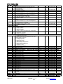
Service Level General Settings:
170
MSB
Room compensation ratio
0…8 [°C]
N3
03 (r), 06(w), 16(w)
170
LSB
Room Control I-time
10…120 [min]
N3
03 (r), 06(w), 16(w)
171
MSB
Room Control I-maximum influence
0…9 [°C]
N3
03 (r), 06(w), 16(w)
171
LSB
Room temperature delay time
0.0…2.0 [h]
N3
03 (r), 06(w), 16(w)
172
MSB
Fire alarm limit
0…90 [°C]
N3
03 (r), 06(w), 16(w)
172
LSB
Frost alarm limit
5…50 [°C]
N6
03 (r), 06(w), 16(w)
173
MSB
Frost protection anticipate temperature
1…12 [°C]
N6
03 (r), 06(w), 16(w)
173
LSB
Startup Increase
0…9 [°C]
N3
03 (r), 06(w), 16(w)

Voimatie 6 Tel. +358 424 8401
OUMAN OY FIN-90440 KEMPELE Fax +358 8 815 5060
www.ouman.fi FINLAND E-mail: ouman@ouman.fi
12/18
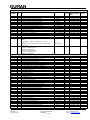
Service Level General Settings cont…
Modbus
Register
Byte/
Bit
Description
Limits
Cate-
gory
Supported
Modbus Function
Codes
Controller
Version
174
MSB
Startup Time (control sequences locked)
0…9 [min]
N3
03 (r), 06(w), 16(w)
174
LSB
Delay between control sequences
0…9 [min]
N3
03 (r), 06(w), 16(w)
175
MSB
Night cooling temperature differential
0.5…5.0 [°C]
N3
03 (r), 06(w), 16(w)
175
LSB
Night cooling inhibit
5…50 [°C]
N3
03 (r), 06(w), 16(w)
176
MSB
Night heating temperature differential
0.5…5.0 [°C]
N3
03 (r), 06(w), 16(w)
176
LSB
Cooling maximum influence °C
1…30 [°C]
N3
03 (r), 06(w), 16(w)
177
MSB
Heating maximum influence °C
1…30 [°C]
N3
03 (r), 06(w), 16(w)
177
LSB
Preheating time
0…8 [h]
N3
03 (r), 06(w), 16(w)
178
MSB
Room temperature deviation alarm limit
1…75 [°C]
N3
03 (r), 06(w), 16(w)
178
LSB
Supply air temperature deviation alarm limit
1…75 [°C]
N3
03 (r), 06(w), 16(w)
179
MSB
Deviation alarm delay time
0…90 [min]
N3
03 (r), 06(w), 16(w)
179
LSB
Supply air flow alarm limit
0.1…9.9 [m/s]
N3
03 (r), 06(w), 16(w)
180
MSB
Exhaust air flow alarm limit
0.1…9.9 [m/s]
N3
03 (r), 06(w), 16(w)
180
LSB
Supply air filter minimum pressure
0…99 [Pa]
N3
03 (r), 06(w), 16(w)
181
MSB
Exhaust air filter minimum pressure
0…99 [Pa]
N3
03 (r), 06(w), 16(w)
181
LSB
Danger of fire from the exhaust temperature
0…90 [°C]
N3
03 (r), 06(w), 16(w)
182
MSB
The exhaust unit is turned off during night heating,
Yes/No
N3
03 (r), 06(w), 16(w)
184
Heating coil return water temperature setpoint
10…40 [°C]
N6
03 (r), 06(w), 16(w)
185
Alarm delay time
0…500 [s]
N3
03 (r), 06(w), 16(w)
186
Supply air filter 1/1-speed pressure alarm limit Pa (filter
alarm)
50…500 [Pa]
N3
03 (r), 06(w), 16(w)
187
Supply air filter 1/2-speed pressure alarm limit Pa (filter
alarm)
50…500 [Pa]
N3
03 (r), 06(w), 16(w)
188
Exhaust air filter 1/1-speed pressure alarm limit Pa (filter
alarm)
50…500 [Pa]
N3
03 (r), 06(w), 16(w)
189
Exhaust air filter 1/2-speed pressure alarm limit Pa (filter
alarm)
50…500 [Pa]
N3
03 (r), 06(w), 16(w)
190
1/1-switch post running time
0…599 [min]
N3
03 (r), 06(w), 16(w)
191
1/2- switch post running time
0…599 [min]
N3
03 (r), 06(w), 16(w)
192
SF fan PDE alarm limit
0…500 [Pa]
N3
03 (r), 06(w), 16(w)
193
EF fan PDE alarm limit
0…500 [Pa]
N3
03 (r), 06(w), 16(w)
194
SF K- value (calculates volume of air )
0…9999
N3
03 (r), 06(w), 16(w)
195
EF K- value (calculates volume of air)
0…9999
N3
03 (r), 06(w), 16(w)
Damper settings:
197
MSB
Damper operation:
0 = Not in use
1 = On/Off
2 = Cascade control
3 = CO2-control
4 = Constant position
5 = Based on outdoor temperature
1…6
N6
03 (r), 06(w), 16(w)
197
LSB
Summertime reverse operation:
0 = Not reverse
1 = Reverse
0…1
N6
03 (r), 06(w), 16(w)
198
MSB
Damper actuator:
1 = 0-10 V
2 = 2-10 V
3 = 10-0 V
1…3
N6
03 (r), 06(w), 16(w)
198
LSB
Damper preopening %
0…100 [%]
N6
03 (r), 06(w), 16(w)
199
MSB
Damper constant mixing ratio
0…100 [%]
N3
03 (r), 06(w), 16(w)
199
LSB
Damper minimum setting %
0…100 [%]
N3
03 (r), 06(w), 16(w)
200
MSB
Damper maximum setting %
0…100 [%]
N3
03 (r), 06(w), 16(w)
200
LSB
Position/Outdoor temperature -> Outdoor temp for
minimum damper position
-30…30 [°C]
N6
03 (r), 06(w), 16(w)
201
MSB
Position/Outdoor temperature -> Outdoor temp for
maximum damper position
-30…30 [°C]
N6
03 (r), 06(w), 16(w)
201
LSB
Fresh air damper night heating position %
0…100 [%]
N6
03 (r), 06(w), 16(w)
202
MSB
Fresh air damper cooling time minimum position %
0…100 [%]
N3
03 (r), 06(w), 16(w)
205
Corresponding to minimum position
500…1800 [ppm]
N3
03 (r), 06(w), 16(w)
206
Corresponding to maximum position
700…2000[ppm]
N3
03 (r), 06(w), 16(w)
207
Damper P-area, °C
5…100 [°C]
N6
03 (r), 06(w), 16(w)
208
Damper I-time
10…500 [s]
N6
03 (r), 06(w), 16(w)
209
Damper D-time
0.0…5.0 [s]
N6
03 (r), 06(w), 16(w)
210
Damper actuator running time
5…150 [s]
N6
03 (r), 06(w), 16(w)
HRU settings:

Voimatie 6 Tel. +358 424 8401
OUMAN OY FIN-90440 KEMPELE Fax +358 8 815 5060
www.ouman.fi FINLAND E-mail: ouman@ouman.fi
13/18
Modbus
Register
Byte/
Bit
Description
Limits
Cate-
gory
Supported Modb.
Function Codes
Controll.
Version
216
MSB
HRU operation:
0 = Not in use
1 = Normal operation
2 = Reverse summer operation
0…2
N6
03 (r), 06(w), 16(w)
216
LSB
HRU frost protection:
0 = Temperature
1 = Pressure switch
2 = Pressure switch 1/1-1/2
3 = Pressure transmitter
0…3
N6
03 (r), 06(w), 16(w)
217
MSB
AHU speed during defrost:
0 = AHU at minimum speed
1 = AHU speed does not change
2 = Supply fan AC freq. converter to minimum position
0…2
N6
03 (r), 06(w), 16(w)
217
LSB
HRU actuator:
1 = 0-10 V
2 = 2-10 V
3 = 10-0 V
1…3
N6
03 (r), 06(w), 16(w)
218
MSB
Frost protection temperature limit
-30…30 [°C]
N6
03 (r), 06(w), 16(w)
218
LSB
HRU defrost pressure hysteresis Pa
0…100 [Pa]
N6
03 (r), 06(w), 16(w)
219
MSB
HRU defrost output %
0..100 [%]
N6
03 (r), 06(w), 16(w)
219
LSB
HRU stand-by position output %
0…100 [%]
N6
03 (r), 06(w), 16(w)
220
MSB
HRU efficiency alarm limit %
0…100 [%]
N6
03 (r), 06(w), 16(w)
223
HRU defrost pressure difference 1/1
10…990 [Pa]
N6
03 (r), 06(w), 16(w)
224
HRU defrost pressure difference 1/2
10…990 [Pa]
N6
03 (r), 06(w), 16(w)
225
HRU defrost post running time
10…500 [s]
N6
03 (r), 06(w), 16(w)
226
HRU P-area
5…100 [°C]
N6
03 (r), 06(w), 16(w)
227
HRU I-time
10…500 [s]
N6
03 (r), 06(w), 16(w)
228
HRU D-time
0.0…5.0 [s]
N6
03 (r), 06(w), 16(w)
229
HRU actuator running time
5…150 [s]
N6
03 (r), 06(w), 16(w)
Heating settings:
235
MSB
Heating stage:
0 = Not in use
1 = Heating radiator
2 = Electrical heater
0…2
N6
03 (r), 06(w), 16(w)
235
LSB
Heating actuator:
1 = 0-10 V
2 = 2-10 V
3 = 10-0 V
1…3
N6
03 (r), 06(w), 16(w)
236
MSB
Frost alarm limit
5…50 [°C]
N6
03 (r), 06(w), 16(w)
236
LSB
Frost risk anticipate temperature
1…12 [°C]
N6
03 (r), 06(w), 16(w)
237
MSB
Start-up position %
0…100 [%]
N6
03 (r), 06(w), 16(w)
237
LSB
Heating hysteresis for electric heaters
0.3…3.0 [°C]
N6
03 (r), 06(w), 16(w)
241
Heating radiator return water temperature setpoint
10.0…40.0 [°C]
N6
03 (r), 06(w), 16(w)
242
Electric heater post ventilation time
0…500 [s]
N6
03 (r), 06(w), 16(w)
243
Heating P-area
5...100 [°C]
N6
03 (r), 06(w), 16(w)
244
Heating I-time
10…500 [s]
N6
03 (r), 06(w), 16(w)
245
Heating D-time
0…5.0 [s]
N6
03 (r), 06(w), 16(w)
246
Heating actuator running time
5…150 [s]
N6
03 (r), 06(w), 16(w)
Cooling settings:
253
MSB
Cooling stage:
0 = Not in use
1 = Stepped
2 = Continuous control
0…2
N6
03 (r), 06(w), 16(w)
253
LSB
Cooling actuator:
1 = 0-10 V
2 = 2-10 V
3 = 10-0 V
1…3
N6
03 (r), 06(w), 16(w)
254
MSB
Heating and cooling temperature differential
1.0 …5.0 [°C]
N6
03 (r), 06(w), 16(w)
254
LSB
Cooling inhibit outdoor temperature
5…50 [°C]
N6
03 (r), 06(w), 16(w)
255
MSB
Night cooling enable temperature limit
20…50 [°C]
N6
03 (r), 06(w), 16(w)
255
LSB
Room/exhaust compensation ratio
1…8 [°C]
N6
03 (r), 06(w), 16(w)
256
MSB
I-maximum influence %
0…100 [%]
N6
03 (r), 06(w), 16(w)
256
LSB
I-maximum influence °C
1…8 [°C]
N6
03 (r), 06(w), 16(w)
257
MSB
Reverse operation delay in minutes
0…8 [min]
N6
03 (r), 06(w), 16(w)
257
LSB
AHU at maximum speed during cooling
0 = No, 1 = Yes
0…1
N6
03 (r), 06(w), 16(w)
260
Supply air temperature controlled cooling P-area
5…100 [°C]
N6
03 (r), 06(w), 16(w)
261
Supply air temperature controlled cooling I-time
10…500 [s]
N6
03 (r), 06(w), 16(w)
262
P-room/exhaust control
1…8 [°C]
N6
03 (r), 06(w), 16(w)
Cooling settings, cont…
Modbus
Byte/
Description
Limits
Cate-
Supported Modb.
Controll.

Voimatie 6 Tel. +358 424 8401
OUMAN OY FIN-90440 KEMPELE Fax +358 8 815 5060
www.ouman.fi FINLAND E-mail: ouman@ouman.fi
14/18
Register
Bit
gory
Function Codes
Version
263
I-room/exhaust control
10…120 [min]
N6
03 (r), 06(w), 16(w)
264
P-minimum limit
5…100 [°C]
N6
03 (r), 06(w), 16(w)
265
I-minimum limit in seconds
10…500 [s]
N6
03 (r), 06(w), 16(w)
266
Cooling actuator running time
5…150 [s]
N6
03 (r), 06(w), 16(w)
AHU Operation:
272
MSB
AHU fan control:
0 = 1/2 and 1/1-speed
1 = 1/1 speed
2 = AC freq.converter control
0…2
N7
03 (r), 06(w), 16(w)
272
LSB
AC freq.converter control method:
0 = Constant pressure
1 = Min-max pressure
2 = Constant speed
3 = Min-max speed
0…3
N7
03 (r), 06(w), 16(w)
273
MSB
AHU outdoor temperature control:
0 = Not in use
1 = In use
0…1
N7
03 (r), 06(w), 16(w)
273
LSB
AHU speed control (cascaded control):
0 = Not in use
1 = In use
0…1
N7
03 (r), 06(w), 16(w)
274
MSB
AHU speed enhancement based on CO2:
0 = Not in use
1 = Auto override
2 = Also external switch override
0…2
N7
03 (r), 06(w), 16(w)
274
LSB
AHU start with CO2-control:
0 = Not in use
1 = In use
0…1
N7
03 (r), 06(w), 16(w)
275
MSB
AHU speed enhancement based on room temperature:
0 = Not in use
1 = Auto override
2 = Also external switch override
0…2
N7
03 (r), 06(w), 16(w)
275
LSB
AHU speed enhancement based on humidity:
0 = Not in use
1 = Auto override
2 = Also external switch override
0…2
N7
03 (r), 06(w), 16(w)
276
MSB
AHU minimum speed %
0…100 [%]
N7
03 (r), 06(w), 16(w)
276
LSB
Supply fan maximum speed %
0…100 [%]
N7
03 (r), 06(w), 16(w)
277
MSB
Supply fan minimum speed %
0…100 [%]
N7
03 (r), 06(w), 16(w)
277
LSB
Exhaust fan maximum speed %
0…100 [%]
N7
03 (r), 06(w), 16(w)
278
MSB
Exhaust fan minimum speed %
0…100 [%]
N7
03 (r), 06(w), 16(w)
278
LSB
Heating boost setpoint
1.5…9.9 [°C]
N7
03 (r), 06(w), 16(w)
279
MSB
Cooling boost setpoint
1.5…9.9 [°C]
N7
03 (r), 06(w), 16(w)
279
LSB
Outdoor temperature for AHU maximum speed
-30…30 [°C]
N7
03 (r), 06(w), 16(w)
280
MSB
Outdoor temperature for AHU minimum speed
-30…30 [°C]
N7
03 (r), 06(w), 16(w)
280
LSB
Room humidity for AHU maximum speed
0…100 [%]
N7
03 (r), 06(w), 16(w)
281
MSB
Room humidity for AHU minimum speed
0…100 [%]
N7
03 (r), 06(w), 16(w)
281
LSB
AHU running indication 1= in use/ 2= not in use
0…1
N7
03 (r), 06(w), 16(w)
282
MSB
AHU post running time (CO2)
0…99 [min]
N7
03 (r), 06(w), 16(w)
282
LSB
AHU reduced output when the ½ switch is active
1 = Allowed, 0 = Not allowed
0…1
N7
03 (r), 06(w), 16(w)
285
Supply air unit channel pressure setting for the maximum
AHU speed
50…990 [Pa]
N7
03 (r), 06(w), 16(w)
286
Exhaust air unit channel pressure setting for the
maximum AHU speed
50…990 [Pa]
N7
03 (r), 06(w), 16(w)
287
Pressure deviation alarm limit at maximum speed
0…300 [Pa]
N7
03 (r), 06(w), 16(w)
288
Supply air unit channel pressure setting for the minimum
AHU speed
50…990 [Pa]
N7
03 (r), 06(w), 16(w)
289
Exhaust air unit channel pressure setting for the minimum
AHU speed
50…990 [Pa]
N7
03 (r), 06(w), 16(w)
290
Pressure deviation alarm limit at AHU minimum speed
0…300 [Pa]
N7
03 (r), 06(w), 16(w)
291
CO2 setting for the maximum AHU speed
700…2000 [ppm]
N3
03 (r), 06(w), 16(w)
292
CO2 setting for the minimum AHU speed
500…1800 [ppm]
N3
03 (r), 06(w), 16(w)
293
Supply pressure control P-band [Pa]
50…990 [Pa]
N7
03 (r), 06(w), 16(w)
294
Supply pressure control I-time
5…100 [s]
N7
03 (r), 06(w), 16(w)
295
Exhaust pressure control P-band [Pa]
50…990 [Pa]
N7
03 (r), 06(w), 16(w)
296
Exhaust pressure control I-time
5…100 [s]
N7
03 (r), 06(w), 16(w)
297
Supply pressure control running time
5…150 [s]
N7
03 (r), 06(w), 16(w)
298
Exhaust pressure control running time
5…150 [s]
N7
03 (r), 06(w), 16(w)
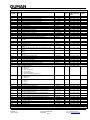
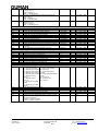
Alarm Configuration:
Modbus
Byte/
Description
Limits
Cate-
Supported Modb.
Controll.

Voimatie 6 Tel. +358 424 8401
OUMAN OY FIN-90440 KEMPELE Fax +358 8 815 5060
www.ouman.fi FINLAND E-mail: ouman@ouman.fi
15/18
Register
Bit
gory
Function Codes
Version
299
Bit1
Acknowledgement method for alarm that stops AHU
0 = local acknowledgement, 1 = also remote
acknowledgement
N7
03 (r), 06(w), 16(w)
299
Bit2
Contradiction alarms:
0 = not in use, 1 = in use
N7
03 (r), 06(w), 16(w)
299
Bit3
AHU start after main pump alarm condition cleared
0 = no acknowledgement, 1 = after acknowledgement
N7
03 (r), 06(w), 16(w)
299
Bit4
AHU start after heating pump alarm condition cleared
0 = no acknowledgement, 1 = after acknowledgement
N7
03 (r), 06(w), 16(w)
299
Bit5
AHU operation in case of flow alarm:
0 = AHU does not stop, 1 = AHU stops
N7
03 (r), 06(w), 16(w)
299
Bit6
Damper position in case of smoke alarm
0 = open, 1 = closed
N7
03 (r), 06(w), 16(w)
299
Bit7
AHU start after emergency stop switch has returned to
normal:
0 = no acknowledgement, 1 = after acknowledgement
N7
03 (r), 06(w), 16(w)
299
Bit8
Postventilation if an alarm stops the AHU:
0 = not carried out, 1 = carried out
N7
03 (r), 06(w), 16(w)
299
Bit9
Postventilation in case of fire risk alarm:
0 = enabled, 1 = disabled
N7
03 (r), 06(w), 16(w)
Temperature control:
300
Bit1
…2
Temperature control:
0 = Supply controlled
1 = Room controlled
2 = Exhaust controlled
3 = Supply controlled with outdoor temp. compensation
0…3
N7
03 (r), 06(w), 16(w)
300
Bit3
…4
AHU heating level control:
0 = Damper min -> Heating
1 = Heating -> Damper min
0…1
N7
03 (r), 06(w), 16(w)
24Vac on/off controls:
0 = Continuous 24 Vac output
1 = Heating valve open (42), Heating valve close (43) or
Damper ON/OFF control (51)
2 = Cooling run permit
3 = Cooling pump control
4 = HRU pump control
5 = Heating pump control
6 = Indicator lamp of timer function
7 = Exhaust damper control
8 = Electric heater heating permit
9 = Regulation control
10 = Night heating indication
301
MSB
Output 42 selection
0…10
N7
03 (r), 06(w), 16(w)
301
LSB
Output 43 selection
0…10
N7
03 (r), 06(w), 16(w)
302
MSB
Output 51 selection
0…10
N7
03 (r), 06(w), 16(w)
Measurement / digital input settings: Note! Look the corresponding index number from the appendix!
304
MSB
Measurement 1 (NTC)
0…63
N7
03 (r), 06(w), 16(w)
304
LSB
Measurement 2 (NTC)
0…63
N7
03 (r), 06(w), 16(w)
305
MSB
Measurement 3 (NTC)
0…63
N7
03 (r), 06(w), 16(w)
305
LSB
Measurement 4 (NTC)
0…63
N7
03 (r), 06(w), 16(w)
306
MSB
Measurement 5 (NTC)
0…63
N7
03 (r), 06(w), 16(w)
306
LSB
Measurement 6 (NTC)
0…63
N7
03 (r), 06(w), 16(w)
307
MSB
Measurement 7 (0-10V)
0…63
N7
03 (r), 06(w), 16(w)
307
LSB
Measurement 8 (0-10V)
0…63
N7
03 (r), 06(w), 16(w)
308
MSB
Measurement 9 (0-10V)
0…63
N7
03 (r), 06(w), 16(w)
308
LSB
Measurement 10 (0-10V)
0…63
N7
03 (r), 06(w), 16(w)
309
MSB
Measurement 11 (0-10V)
0…63
N7
03 (r), 06(w), 16(w)
309
LSB
Digital Input 21
0…63
N7
03 (r), 06(w), 16(w)
310
MSB
Digital Input 22
0…63
N7
03 (r), 06(w), 16(w)
310
LSB
Digital Input 23
0…63
N7
03 (r), 06(w), 16(w)
311
MSB
Digital Input 24
0…63
N7
03 (r), 06(w), 16(w)
311
LSB
Digital Input 25
0…63
N7
03 (r), 06(w), 16(w)
312
MSB
Digital Input 26
0…63
N7
03 (r), 06(w), 16(w)
312
LSB
Digital Input 27
0…63
N7
03 (r), 06(w), 16(w)
313
Bit7
Outdoor temperature measurement from bus
1 = In use
N7
03 (r), 06(w), 16(w)
314
Bit15
Room temperature measurement from bus,1 = In use
N7
03 (r), 06(w), 16(w)
314
Bit7
CO2 measurement from bus
1 = In use
N7
03 (r), 06(w), 16(w)
Measurement / digital input settings, cont…
Modbus
Register
Byte/
Bit
Description
Limits
Cate-
gory
Supported Modb.
Function Codes
Controller
Version

Voimatie 6 Tel. +358 424 8401
OUMAN OY FIN-90440 KEMPELE Fax +358 8 815 5060
www.ouman.fi FINLAND E-mail: ouman@ouman.fi
16/18
315
Bit8
…15
Main pump running status from bus
Bit15: In use = 1
Bit14: Inverted = 1
Bit8…11: Bit being read
N7
03 (r), 06(w), 16(w)
315
Bit0
…7
Heating circuit water pressure measurement from bus
Bit7: In use = 1
Bit6: : Inverted = 1
Bit0…3: Bit being read
N7
03 (r), 06(w), 16(w)
316
Bit8
…15
Emergency stop from bus
Bit15: In use = 1
Bit14: Inverted = 1
Bit8…11: Bit being read
N7
03 (r), 06(w), 16(w)
Transmitter ranges:
319
Room temperature transmitter minimum
-20.0…0.0 [°C]
N7
03 (r), 06(w), 16(w)
320
Room temperature transmitter maximum
0.0…100.0 [°C]
N7
03 (r), 06(w), 16(w)
321
Supply air temperature transmitter maximum
0…5000 [Pa]
N7
03 (r), 06(w), 16(w)
322
Exhaust air temperature transmitter maximum
0…5000 [Pa]
N7
03 (r), 06(w), 16(w)
323
Supply air pressure transmitter maximum
0…990 [Pa]
N7
03 (r), 06(w), 16(w)
324
Exhaust air pressure transmitter maximum
0…990 [Pa]
N7
03 (r), 06(w), 16(w)
325
CO2-transmitter minimum
0…2000 [ppm]
N7
03 (r), 06(w), 16(w)
326
CO2- transmitter maximum
0…2000 [ppm]
N7
03 (r), 06(w), 16(w)
327
Supply air flow transmitter maximum
0.0…10.0 [m/s]
N7
03 (r), 06(w), 16(w)
328
Exhaust air flow transmitter maximum
0.0…10.0 [m/s]
N7
03 (r), 06(w), 16(w)
329
Supply air filter differential pressure transmitter maximum
0…990 [Pa]
N7
03 (r), 06(w), 16(w)
330
Exhaust air filter differential pressure transmitter
maximum
0…990 [Pa]
N7
03 (r), 06(w), 16(w)
331
HRU differential pressure transmitter maximum
0…990 [Pa]
N7
03 (r), 06(w), 16(w)
Transmitter types: 0 = 0-10 V 1 = 2-10 V 2 = 4-20 mA
333
MSB
Supply air flow transmitter type
0…2
N7
03 (r), 06(w), 16(w)
333
LSB
Exhaust air flow transmitter type
0…2
N7
03 (r), 06(w), 16(w)
334
MSB
Supply air pressure transmitter type
0…2
N7
03 (r), 06(w), 16(w)
334
LSB
Exhaust air pressure transmitter type
0…2
N7
03 (r), 06(w), 16(w)
335
MSB
Supply air filter pressure transmitter type
0…2
N7
03 (r), 06(w), 16(w)
335
LSB
Exhaust air filter pressure transmitter type
0…2
N7
03 (r), 06(w), 16(w)
336
MSB
HRU differential pressure transmitter type
0…2
N7
03 (r), 06(w), 16(w)
336
LSB
SF pressure difference transmitter type
0…2
N7
03 (r), 06(w), 16(w)
337
MSB
EF pressure difference transmitter type
0…2
N7
03 (r), 06(w), 16(w)
Text fields read/write:
339
Selection of text field
0…15
-
03 (r), 06(w), 16(w)
0 = Free measurement
1 = Normally open alarm1
2 = Normally open alarm2
3 = Normally open alarm3
4 = Normally open alarm4
5 = Normally closed
alarm1
6 = Normally closed
alarm 2
7 = Alarm phone number
GSM1
8 = Alarm phone number
GSM2
9 = SMS center number
10 = PIN-code
11 = Datamodem phone
number
12 = Datamodem initialisation
string
13 = Device ID
14 = Locking code
15 = Header
340
MSB
Selected text field first character
N5
03 (r), 06(w), 16(w)
340
LSB
Selected text field second character
N5
03 (r), 06(w), 16(w)
…
…
354
MSB
Selected text field last but one character
N5
03 (r), 06(w), 16(w)
354
LSB
Selected text field last character
N5
03 (r), 06(w), 16(w)
400
Shows if the data update between the controller and the
Modbus card for categories N1-N7 is in progress or if it
has been completed
0x0000 = update completed
0x00FF = update in progress
-
03 (r)

Voimatie 6 Tel. +358 424 8401
OUMAN OY FIN-90440 KEMPELE Fax +358 8 815 5060
www.ouman.fi FINLAND E-mail: ouman@ouman.fi
17/18
Modbus
Register
Byte/
Bit
Description
Limits
Cate-
gory
Supported Modb.
Function Codes
Controller
Version
Special Registers:
500 – 516
Window registers, see Document 6.1
2000 – 2354
MSB mirror registers, see Document 6.2
4000 – 4354
LSB mirror registers, see Document 6.2
6000 – 6709
MSB + LSB mirror registers, see Document 6.2
Controller Type:
Object value,
Object Id 01
Controller type
43
Objext value,
Object Id 02
Firmware version (e.g. 140 = 1.40)
43
9 Appendix 2: Alarm index
101 = Sensor fault, Outdoor air temperature
102 = Sensor fault, Supply air temperature
103 = Sensor fault, Exhaust air temperature
104 = Sensor fault, Room temperature
105 = Sensor fault, Supply air temperature B
106 = Sensor fault, Room temperature B
107 = Sensor fault, Radiator return water temperature
108 = Sensor fault, Exhaust air temperature after HRU
109 = Sensor fault, Supply air temperature after HRU
110 = Sensor fault, External set point potentiometer
111 = Sensor fault, Free measurement (description user
definable)
112 = Frost alarm, Heating radiator return water temp.
113 = Deviation alarm, Supply temperature
114 = Deviation alarm, Exhaust temperature
115 = Deviation alarm, Room temperature
116 = Deviation alarm, Supply air pressure
117 = Deviation alarm, Exhaust air pressure
118 = Deviation alarm, Supply air temperature
119 = Efficiency alarm, HRU efficiency
120 = General alarm, Normally open general alarm 1
(before the version 1.42)/ Alarm, Overheating protection
of the electric heater (from the version 1.42) (B)
121 = General alarm, Normally open general alarm 2
(before the version 1.42)/ Not in use (from the version
1.42) (B)
122 = General alarm, Normally open general alarm 3 (B)
123 = General alarm, Normally open general alarm 4 (B)
124 = General alarm, Normally closed general alarm 1
(before the version 1.42)/ Not in use (from the version
1.42) (B)
125 = General alarm, Normally closed general alarm 2
126 = Filter alarm, supply air filter pressure transmitter
127 = Filter alarm, exhaust air filter pressure transmitter
128 = Filter alarm, supply air filter differential pressure
switch
129 = Filter alarm, exhaust air filter differential pressure
switch
130 = Flow alarm, supply air flow
131 = Flow alarm, exhaust air flow
132 = Flow alarm, supply air filter transmitter minimum
pressure
133 = Flow alarm, exhaust air filter transmitter minimum
pressure
134 = Contradiction alarm, SF 1/1 speed
135 = Contradiction alarm, SF 1/2 speed
136 = Contradiction alarm, EF 1/1 speed
137 = Deviation alarm, EF 1/1 speed
138 = Contradiction alarm, EF 1/2 speed
139 = Deviation alarm, EF 1/2 speed
140 = Contradiction alarm, SF pressure switch
141 = Contradiction alarm, FF pressure switch
142 = Contradiction alarm, 230 V run information
143 = External switch, SF AC freq.converter override switch
144 = Contradiction alarm, SF AC freq. converter override
switch
145 = External switch, EF AC freq. converter override switch
146 = Contradiction alarm, EF AC freq. converter override
switch
147 = Deviation alarm, EF AC freq. converter override switch
148 = Pump alarm, Heating pump running info
149 = Pump alarm, Main pump running info
150 = Pump alarm, HRU pump running info
151 = Pump alarm, Cooling pump running info
152 = Overheat alarm, Electric heater
153 = Overload alarm, SF 1/1 overload relay
154 = Overload alarm, SF 1/2 overload relay
155 = Overload alarm, EF 1/1 overload relay
156 = Overload alarm, EF 1/2 overload relay
157 = Overload alarm, Heating pump overload relay
158 = Overload alarm, HRU pump overload relay
159 = Overload alarm, Cooling pump overload relay
160 = Pressure alarm, Heating circuit pressure switch
161 = Pressure alarm, HRU glycol circuit pressure switch
162 = Alarm, Smoke alarm
163 = Alarm, Emergency Stop switch
164 = Alarm, Service alarm
165 = Alarm, HRU rotation speed
166 = Alarm, Cooling plant failure
167 = Freezing risk alarm, Room temperature
168 = Pressure alarm SF fan PDE (from the version 1.42)
169 = Pressure alarm, EF fan PDE (from the version 1.42)
170 = Deviation alarm, SF fan PDE (from the version 1.42)
171 = Deviation alarm, EF fan PDE (from the version 1.42)

Voimatie 6 Tel. +358 424 8401
OUMAN OY FIN-90440 KEMPELE Fax +358 8 815 5060
www.ouman.fi FINLAND E-mail: ouman@ouman.fi
18/18
10 Appendix 3: Index numbers for measurements and switches for Modbus-registers
304 – 312
0 = Not in use
1 = Outdoor temperature
2 = Supply air temperature
3 = Supply air temperature 2
4 = Room temperature
5 = Exhaust air temperature
6 = Room temperature 2
7 = Return water temperature
8 = HRU frost protection
9 = Supply air temperature after HRU
10 = External setpoint potentiometer
11 = Free measurement
12 = Room temperature (transmitter)
13 = Exhaust air temperature (transmitter)
14 = Supply air pressure
15 = Exhaust air pressure
16 = CO2-content
17 = Room air humidity
18 = Supply air flow
19 = Exhaust air flow
20 = Supply air filter differential pressure
21 = Exhaust air filter differential pressure
22 = Differential pressure over HRU
23 = Exhaust fan differential pressure
(from the version v. 1.42)
24 = AHU 1/1 external override switch
25 = AHU 1/2 external override switch
26 = AHU 0 external override switch
27 = Emergency stop external override switch
28 = SF 1/1 speed running info
29 = SF 1/2 speed running info
30 = EF 1/1 speed running info
31 = EF 1/2 speed running info
32 = Heating pump running info
33 = SF freq. converter override switch
34 = EF freq. converter override switch
35 = Main pump running info
36 = SF 1/1 overload relay
37 = SF 1/2 overload relay
38 = EF 1/1 overload relay
39 = EF 1/2 overload relay
40 = Heating pump overload relay
41 = HRU differential pressure switch - 1/1 speed
42 = HRU differential pressure switch - 1/2 speed
43 = Supply fan pressure switch
44 = Exhaust fan pressure switch
45 = Supply filter pressure switch
46 = Exhaust filter pressure switch
47 = Electric heater overheat
48 = External temperature setting override switch
49 = Smoke alarm
50 = HRU pump running info
51 = HRU pump overload relay
52 = Heating circuit water pressure
53 = HRU glycol circuit pressure
54 = HRU rotation speed alarm
55 = Cooling plant alarm
56 = Cooling pump running info
57 = Cooling pump overload relay
58 = General alarm normally open 1
59 = General alarm normally open 2
60 = General alarm normally open 3
61 = General alarm normally open 4
62 = General alarm normally closed 1
63 = General alarm normally closed 2
EH105 modbus english V-1.3.doc_ 17022015
-
 1
1
-
 2
2
-
 3
3
-
 4
4
-
 5
5
-
 6
6
-
 7
7
-
 8
8
-
 9
9
-
 10
10
-
 11
11
-
 12
12
-
 13
13
-
 14
14
-
 15
15
-
 16
16
-
 17
17
-
 18
18


w innych językach
- English: OUMAN MODBUS-100 User manual
Powiązane artykuły
Inne dokumenty
-
Mark PinTherm Connect Technical Manual
-
Komfovent BACnet Instrukcja instalacji
-
Sierra InnovaMass 240i/241i Modbus Instrukcja obsługi
-
-
Komfovent BACNET connection C8 Instrukcja obsługi
-
-
-
Moxa ioLogik R1200 Series Instrukcja obsługi
-
-