
www.classicexhibits.com
Step 1
Page 1 of 2
866.652.2100
© 2013
WHEN DISASSEMBLING ALUMINUM EXTRUSION, TIGHTEN ALL
SETSCREWS AND LOCKS TO PREVENT LOSS DURING SHIPPING
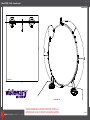
Order #XXXXX - 10x10 - General Layout
10’
10’
Plan View
Perspective View

www.classicexhibits.com
Step 2
Page 2 of 2
866.652.2100
© 2013
WHEN DISASSEMBLING ALUMINUM EXTRUSION, TIGHTEN ALL
SETSCREWS AND LOCKS TO PREVENT LOSS DURING SHIPPING
Order #XXXXX - General Information
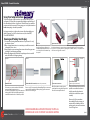
The Tool Typical Connection
Horizontal Inline Connection (remove only one setscrew)
Base Plate Connection Vertical Connection
(remove only two setscrews)
Most Visionary Designs exhibits can be
assembled with the supplied Hex Key Tool.
Occasionally, a flat head screwdriver may
be required.
Most horizontal extrusion connections have a patented expandable lock. This lock inserts into
the groove of an opposing extrusion. Tightening the lock with the Hex Key Tool expands the lock
and creates a strong positive connection.
Remove only (1) setscrew when disassembling. Replace setscrew in
extrusion after assembling it. Before packing, replace setscrew in
extrusion to avoid losing it.
Attach base plate to round or square
vertical extrusion using the bolt provided.
Be careful not to strip the threads.
When vertical extrusions are packed in
portable cases rather than crates or
tubs, they must broken down into
smaller sections which then require
assembly.
Remove only (2) setscrews when
disassembling. Replace setscrews in
extrusion after assembling it. Before
packing, replace setscrews in extrusion
to avoid losing them.
Using Your Setup Instructions
The Visionary Designs Setup Instructions are created specifically for your
configuration. They are laid out sequentially, including an exploded view of
the entire display, and then a logical series of detailed steps to assemble the
main structure and components. We encourage you to study the instructions
before attempting to assemble your exhibit.
Each page reminds you to tighten the setscrews after disassembling your
exhibit to prevent loss of the locks and setscrews (see below in RED).
This is VERY IMPORTANT.
Cleaning and Packing Your Display
1) Use care when cleaning aluminum extrusion or acrylic inserts. Use only
non-abrasive cleaners.
2) When cleaning laminate inserts or countertops, use mild cleansers and a
soft material such as cotton.
3) Keep all display components away from extreme heat and long exposure
to sunlight to avoid warping and fading.
4) Retain all packing material. It will make re-packing much easier and will
reduce the likelihood of shipping damage.
Typical Connection (cont’d)
Numbered Label
Each extrusion contains a numbered label which
corresponds with setup instructions.
The label is located within a groove of the extrusion
(when possible). With Visionary Designs the labels
contain Black numbers unless otherwise specified.
Detail C E liateDD liateDDetail B
Detail A
Setscrews

www.classicexhibits.com
Step 1
Page 1 of 2
866.652.2100
© 2013
WHEN DISASSEMBLING ALUMINUM EXTRUSION, TIGHTEN ALL
SETSCREWS AND LOCKS TO PREVENT LOSS DURING SHIPPING
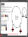
Order #XXXXX - Backwall Aero Frame Assembly
Connections are made by holding the button
down and sliding the red tube into opposing
tube until the connection is made. To disassemble
push button and pull or twist extrusions apart.
Push-Button
Push-Button
66
6
6
Numbered Label
Using Your Setup Instructions
The Aero Overhead Sign Setup Instructions are created specically for your conguration. They include an
exploded view of the frame which is sequentially numbered. We encourage you to study the instructions
before attempting to assemble your exhibit.
Connections are kept very simple: no tools. Everything assembles with push-button
connectors and pre-connected horizontal sections.
Cleaning and Packing Your Display
1) Use care when cleaning aluminum extrusion or acrylic inserts. Use only non-abrasive cleaners.
2) Retain all packing material. It will make re-packing much easier and will reduce the likelihood
of shipping damage.
A2
A1
A6
A5
A4
A3
When
assembled
Steps:
1) Assemble aero pieces
together in numerical order.
2) Apply pillow case graphic
atop assembled aero frame.
3) Attach base plates to
aero frame using bolts.

www.classicexhibits.com
Step 2
Page 2 of 2
866.652.2100
© 2013
WHEN DISASSEMBLING ALUMINUM EXTRUSION, TIGHTEN ALL
SETSCREWS AND LOCKS TO PREVENT LOSS DURING SHIPPING
Order #XXXXX -
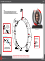
Backwall Assembly (Cont’d)
When assembled
Graphic
Wing
Wing
Wing
Wing
Wing
Wing
Steps:
1) Attach light atop assembled backwall aero frame. Refer to detail.
2) Attach wings to assembled backwall aero frame. Refer to detail.
3) Attach round header to assembled backwall aero frame. Refer to detail.
Tighten set screw to
secure A10 to extrusion.
A10 Clamp Detail
Tighten knob to secure
header/wing in place.
Light Connection
Attach light to
backwall where
desired and tighten
in place.
*
*
Graphic
Screw
Cap
Stand-Off
Barrel
Screw stand-off barrels into
threaded Hole. Attach graphic
to stand-offs using screw caps.
Graphic Attachment
Threaded
Hole
*
*
-
 1
1
-
 2
2
-
 3
3
-
 4
4


Classic Exhibits TF-508 Setup Instructions
- Typ
- Setup Instructions
w innych językach
- English: Classic Exhibits TF-508
Powiązane artykuły
-
Classic Exhibits TF-511 Setup Instructions
-
-
-
-
-
-
-
-
-