Classic Exhibits VK-1901 Setup Instructions
- Typ
- Setup Instructions

© 2017
www.classicexhibits.com
Order #XXXXX
SETUP INSTRUCTIONS
If you would like to tell us about your experience with your setup instructions please email us at [email protected]
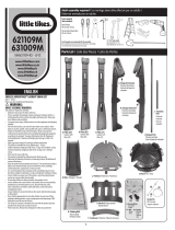
VK-1901 10’x10’ Inline Display
Plan View
10’
10’

© 2017
www.classicexhibits.com
Order #XXXXX
DO NOT USE POWER TOOLS
ALL CONNECTIONS MUST
BE TIGHTLY SECURED
Part Identification - Numbering
Spline Connection Base Plate & Extrusion Connection
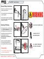
General Setup Instructions
- Read entire setup instruction manual prior to
unpacking parts and pieces.
- The setup instructions are created specifically
for this configuration.
- Setup instructions are laid out sequentially in
steps, including exploded views with detailed
explanation for assembly.
WARNING
Cleaning & Packing
- For Cleaning Metal, Plex, & Laminate Parts:
Use a MILD NON-ABRASIVE cleanser and
soft cloth/paper towel to clean all surfaces.
- Keep exhibit components away from heat
and prolonged sun exposure.
Heat and UV exposure will warp and
fade components.
- Retain all provided Packing Materials.
All provided packing materials are for
ease of repacking & component protection.
Disassembly
- For loss prevention, tighten all setscrews
and locks during disassembly
7A
Hex Tool - Essential for Assembly
Extrusion & Lock Connection Engaged Lock
LADDERS OR LIFTS
MAY BE REQUIRED
General Information

© 2017
www.classicexhibits.com
Order #XXXXX
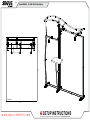
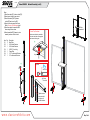
Step 1 of 4
Backwall Assembly
When
assembled
When
assembled
Item
B1
B2
B3
B4
B5
B6
C1
C2
C3
C4
C5
C6
C7
C8
Qty.
1
1
1
1
1
1
1
1
1
1
1
1
1
1
Description
TSP46 Assembly
TSP46 Assembly
17.75”w TSP46 Horizontal Extrusion
31.8205”h TSP46 Vertical Extrusion
31.8205”h TSP46 Vertical Extrusion
17.75”w TSP46 Horizontal Extrusion
40”h TSP46 Vertical Extrusion
40”h TSP46 Vertical Extrusion
35.0625”w TSP46 Horizontal Extrusion
35.0625”w TSP46 Horizontal Extrusion
40”h TSP46 Vertical Extrusion
40”h TSP46 Vertical Extrusion
35.0625”w TSP46 Horizontal Extrusion
35.0625”w TSP46 Horizontal Extrusion
Steps:
1) Assemble TSP46 frame pieces [B1-B6] together.
2) Assemble TSP46 frame pieces [C1-C8] together.
1A
2A
3A
3B
2B
1B
TSP46
Lock
Tighten setscrew
to secure
extrusions
TSV1 Lock Detail

© 2017
www.classicexhibits.com
Order #XXXXX
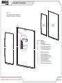
Step 2 of 4
Backwall Assembly (cont’d)
When
assembled
D1
D1
D2
D3
D4
D6
D7
D5
Item
D1
D2
D3
D4
D5
D6
D7
Qty.
3
1
1
1
1
1
1
Description
Base Plate
42”h Vertical Extrusion
42”h Vertical Extrusion
42.0581” Curved Leg
Flange Plate
10.111”w Horizontal Extrusion
11.5”w Horizontal Extrusion
Steps:
1) Attach base plate [D1] to lower vertical [D2].
2) Attach upper vertical to lower vertical.
3) Attach horizontals [D6,D7] between
vertical [D2] and curved leg [D4].
4) Attach counter atop support as shown.
Refer to Counter Top Attachment detail.
5) Attach base plates to assembled SEG
frames using bolts as shown.
6) Attach assembled SEG frames to center
assembly as shown. Refer to detail.
Top View
Cam Lock
Tighten screw to
clamp cam lock
into groove of
vertical extrusion.
Custom
Cam Lock
**
*
*
*
*
*
Counter Top Attachment
Insert screws located on underside
of counter into holes on flange plate
and secure with wing nuts.
Wing Nut
D1

© 2017
www.classicexhibits.com
Order #XXXXX
Step 3 of 4
Connections are made by holding the button
down and sliding the red tube into opposing
tube until the connection is made. To disassemble
push button and pull or twist extrusions apart.
Push-Button
Push-Button
66
6
6
Numbered Label
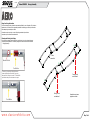
Using Your Setup Instructions
The Aero Overhead Sign Setup Instructions are created specically for your conguration. They include an
exploded view of the frame which is sequentially numbered. We encourage you to study the instructions
before attempting to assemble your exhibit.
Connections are kept very simple: no tools. Everything assembles with push-button
connectors and pre-connected horizontal sections.
Cleaning and Packing Your Display
1) Use care when cleaning aluminum extrusion or acrylic inserts. Use only non-abrasive cleaners.
2) Retain all packing material. It will make re-packing much easier and will reduce the likelihood
of shipping damage.
Canopy Assembly
A/A
B/B C/C
D/D
E/E
F/F
G/G
H/H
When
assembled
Assemble aero pieces
together as shown.
Canopy mount
onto backwall
Canopy mount
onto backwall

© 2017
www.classicexhibits.com
Order #XXXXX
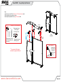
Step 4 of 4
Canopy, Wing & Light Attachment
When
assembled
Wing
Canopy
Canopy
Mount
Steps:
1) Attach wing to vertical. Refer to Example of A10 Clamp Attachment detail.
2) Set canopy atop canopy mounts as shown.
3) Attach lights atop backwall. Refer to Light Connection detail.
Light Connection
Attach lights to
backwall where
desired and
tighten in place.
When desired location
is found, tighten
set screw to secure.
Slide connector on back
of A10 clamp into groove
of extrusion.
Example of A10 Clamp Attachment
Tighten knob to secure
shelf/wing in place.
**** See attached SEG graphic
installation for graphic attachment
-
 1
1
-
 2
2
-
 3
3
-
 4
4
-
 5
5
-
 6
6


Classic Exhibits VK-1901 Setup Instructions
- Typ
- Setup Instructions
w innych językach
- English: Classic Exhibits VK-1901
Powiązane artykuły
-
Classic Exhibits TF-5201 Setup Instructions
-
-
-
-
-
-
-
-
-