
CAME S.p.A.
Via Martiri Della Libertà, 15
31030 - Dosson di Casier
Treviso - Italy
806SA-0090
+-
24 0
24 0
30 0
30 0
12 V - 7 Ah
12 V - 7 Ah
+ -
+-
ZN8
+-
30V 0 24V 0
12 V - 7 Ah
12 V - 7 Ah
RGP1
+ STB -
+ STB -
0 24V
BOARD
TRANSF.
0 24V
0 30V
0 30V
FA01213M4C - 10/2018
FA01231M4C
P
L
P
olsk
i
H
U
M
a
gy
a
r
HR
H
rvatsk
i
U
K
Укра
ї
нська
POLSKI
Ostrzeżenia ogólne
Prosimy ouważne przeczytanie instrukcji przed
przystąpieniem do instalacji i wykonaniem
czynności wskazanych przez producenta.
Instalacja, wprowadzenie do użytku
i konserwacja produktu muszą być
wykonywane przez personel wykwalifikowany
i doświadczony, zgodnie z obowiązującymi
przepisami.
Przed wykonaniem jakiejkolwiek czynności
związanej zczyszczeniem lub wymianą części
należy odłączyć zasilanie od urządzenia.
Produkt należy wykorzystywać wyłącznie
do celu, do jakiego zostało jednoznacznie
przeznaczone, a jakiekolwiek inne jego
wykorzystanie jest uważane za niebezpieczne.
Came S.p.A. nie ponosi odpowiedzialności
za ewentualne szkody wynikające z
błędnego, niewłaściwego lub nierozsądnego
użytkowania.
Przygotowanie przewodów, montaż,
podłączenie i próba techniczna muszą zostać
przeprowadzone zgodnie ze sztuką i zgodnie z
obowiązującymi przepisami.
Produkt jest zgodny z właściwymi dyrektywami
obowiązującymi w czasie produkcji.
WYCOFANIE Z UŻYTKU I UTYLIZACJA – Nie
zanieczyszczać środowiska opakowaniem i
urządzeniem po zakończeniu okresu eksploatacji,
ale poddać je utylizacji zgodnie z przepisami
obowiązującymi w kraju użytkowania urządzenia.
Elementy podlegające recyklingowi noszą symbol i
kod materiału.
NIE WYRZUCAĆ DO ŚRODOWISKA!
PRODUCENT ZASTRZEGA SOBIE PRAWO
WPROWADZANIA ZMIAN W TREŚCI INSTRUKCJI
W DOWOLNEJ CHWILI BEZ WCZEŚNIEJSZEGO
POWIADOMIENIA.
Opis
806SA-0090 Zestaw akumulatorów
zapewniający działanie w przypadku przerwania
dostawy zasilania oraz umożliwiający ładowanie
akumulatorów na napędzie z serii BKV.
Dane techniczne
Model
806SA-0090
Stopień ochrony (IP) 20
Zasilanie (V – 50/60 Hz) 24 AC/DC
Pobór prądu wtrybie Stand-by
[mA] 20
Pobór prądu (mA) 400
Maks. pobór prądu (mA) 730
Napięcie progowe rozładowanego
akumulatora (V) 18 DC
Napięcie wyjściowe (V) 27 DC
Temperatura robocza (°C) od -20 do
+55
Klasa izolacji III
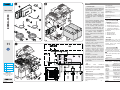
Opis części składowych
1 – Karta LBB
2 – Kabel przyłączeniowy 24 V – 0
3 – Kabel przyłączeniowy 30 V – 0
4 – Czerwony kabel do akumulatora
5 – Czarny kabel do akumulatora
6 – Kabel mostkowy do podłączenia
akumulatorów
7 – Tabliczka zaciskowa
8 – kontrolka LED stanu
9 – Wkładka topikowa 10 A
Montaż
Karta LBB musi zostać wsunięta w
odpowiednie prowadnice karty nośnej.
Baterie buforowe (nie wchodzące w skład
zestawu) muszą zostać umieszczone w
odpowiedniej komorze.
Połączenia elektryczne
Przygotować kable elektryczne i podłączyć
je do karty LBB, jak na rysunku.
Dla połączenia z modułem RGP1 (Green
Power), patrz odpowiedni podręcznik.
DIODY stanu
Kolor Funkcja
Zielone zapalone
Obecność napięcia
sieciowego. Ładowanie
akumulatora ukończone.
Zielone
migające
Napięcie sieciowe obecne w
fazie ładowania akumulatora.
Niebieskie
zapalone Działanie akumulatorowe.
Niebieskie
migające
Działanie akumulatorowe.
Tryb Green Power aktywny.
Czerwone
zapalone
Akumulator rozładowany
(karta nie jest zasilana)
Czerwone
migające
Sprawdzenie stanu
akumulatora po wymianie.
Czerwone
i zielone
migające.
Akumulator odłączony lub
bezpiecznik LBB spalony

FA01213M4C - 10/2018
ITALIANO
Avvertenze generali
Leggere attentamente le istruzioni prima
di iniziare l’installazione ed eseguire
gli interventi come specificato dal
costruttore.
L’installazione, la messa in servizio e la
manutenzione devono essere effettuate
da personale qualificato ed esperto e nel
pieno rispetto delle normative vigenti.
Prima di effettuare qualunque operazione
di pulizia, manutenzione o sostituzione
di parti, togliere l’alimentazione al
dispositivo.
Il prodotto deve essere destinato solo
all’uso per il quale è stato espressamente
studiato e ogni altro uso è da considerarsi
pericoloso.
Came S.p.A. non è responsabile per
eventuali danni causati da usi impropri,
erronei ed irragionevoli.
La predisposizione dei cavi, la posa in
opera, il collegamento e il collaudo si
devono eseguire osservando la regola
dell’arte e in ottemperanza alle norme e
leggi vigenti.
Il prodotto è conforme alle direttive applicabili,
vigenti al momento della fabbricazione.
DISMISSIONE E SMALTIMENTO - Non
disperdere nell’ambiente l’imballaggio e il
dispositivo alla fi ne del ciclo di vita, ma smaltirli
seguendo le norme vigenti nel paese di utilizzo
del prodotto. I componenti riciclabili riportano
simbolo e sigla del materiale.
NON DISPERDERE NELL’AMBIENTE!
I CONTENUTI DEL MANUALE SONO DA
RITENERSI SUSCETTIBILI DI MODIFICA IN
QUALSIASI MOMENTO SENZA OBBLIGO DI
PREAVVISO.
Descrizione
806SA-0090 Kit batteria per il funzionamento in
caso di blackout e per la ricarica delle batterie su
automazione serie BKV.
Dati tecnici
Modello
806SA-0090
Grado di protezione (IP) 20
Alimentazione (V - 50/60 Hz) 24 AC - DC
Assorbimento in stand-by (mA) 20
Assorbimento (mA) 400
Assorbimento max (mA) 730
Tensione di soglia batteria
scarica (V) 18 DC
Tensione di uscita (V) 27 DC
Temperatura di esercizio (°C) -20 ÷ +55
Classe di isolamento III
Descrizione delle parti
1 - Scheda LBB
2 - Cavo di collegamento 24 V - 0
3 - Cavo di collegamento 30 V - 0
4 - Cavo rosso per batteria
5 - Cavo nero per batteria
6 - Cavo ponte per collegamento batterie
7 - Morsettiera
8 - LED di stato
9 - Fusibile di ricambio da 10 A
Installazione
La scheda LBB va inserita sulle guide
predisposte del porta schede.
Le batterie a tampone (non fornite) vanno
inserite nell’apposito vano.
Collegamenti elettrici
Predisporre i cavi elettrici e collegarli alla
scheda LBB come da disegno.
Per il collegamento con il modulo RGP1
(Green Power), vedere relativo manuale.
LED di stato
Colore Funzione
Verde acceso Tensione di linea presente.
Carica batteria completata.
Verde
lampeggiante
Tensione di linea presente
in fase di carica della batteria.
Blu acceso Funzionamento a batteria.
Blu
lampeggiante
Funzionamento a batteria.
Modalità Green Power attiva.
Rosso acceso Batteria scarica (scheda non
alimentata)
Rosso
lampeggiante
Verifi ca stato della batteria
dopo sostituzione.
Rosso e Verde
lampeggianti
Batteria scollegata, fusibile
scheda LBB bruciato o
batteria completamente
carica
ENGLISH
General Precautions
Read the instructions carefully before
beginning the installation and carry
out the actions as specified by the
manufacturer.
Installing, commissioning and
maintenance must only be done
by qualified, expert staff and in full
compliance with applicable laws.
Before doing any cleaning or maintaining
or parts-replacing, cut off the mains
power supply.
Use this product only for its specifically
intended use. Any other use is hazardous.
Came S.p.A. is not liable for any damage
caused by improper, wrongful and
unreasonable use.
Laying of cables, installation and testing
must follow state-of-the-art procedures
as dictated by applicable standards and
laws.
This product conforms to the, standing,
applicable directives when manufactured.
DISMANTLING AND DISPOSAL - Dispose of
the packaging and the device at the end of
its life cycle responsibly, in compliance with
the laws in force in the country where the
product is used. The recyclable components
are marked with a symbol and the material's
ID marker.
DISPOSE OF RESPONSIBLY!
THE CONTENTS OF THIS MANUAL MAY
CHANGE, AT ANY TIME, AND WITHOUT
NOTICE.
Description
806SA-0090 - Battery kit for operating even
during power outages and recharging the
batteries on DKV series automation.
Technical data
Model
806SA-0090
Protection rating (IP) 20 series
Power supply (V - 50/60 Hz) 24 AC - DC
Consumption in stand-by mode
(mA) 20 series
Current draw (mA) 400 series
Maximum draw (mA) 730 series
Low battery threshold voltage
(V) 18 DC
Output voltage (V) 27 DC
Operating temperature (°C) -20 to +55
Insulation class III
Description of parts
1 - LBB board
2 - Connection cable 24 V - 0
3 - Connection cable 30 V - 0
4 - Red cable for battery
5 - Black cable for battery
6 - Jumper cable for batteries connection
7 - Terminal board
8 - State LED
9 - Spare 10 A fuse
Installation
The LBB board must be inserted on the
board holder prearranged guides.
The buffer batteries (not supplied) must be
inserted in the appropriate compartment.
Electrical wiring
Prearrange the electric cables and connect
them to the LBB board as shown in the
drawing.
For connection to the RGP1 (Green
Power) module, see the corresponding
manual.
State LED
Colour Function
Green on Incoming voltage on. Battery
charge completed.
Flashing green Line voltage present during
battery charging.
Blue on Battery operation.
Blue fl ashing Battery operation. Green
Power mode active.
Red on Low battery (board not
powered)
Red fl ashing Battery status check after
replacement.
Red and Green
fl ashing
Battery disconnected or burnt
LBB board fuse
FRANÇAIS
Instructions générales
Lire attentivement les instructions avant
toute opération d'installation et effectuer
les interventions comme indiqué par le
fabricant.
L’installation, la programmation, la mise
en service et l'entretien doivent être
effectués par du personnel qualifié et
dans le plein respect des normes en
vigueur.
Avant toute opération de nettoyage,
d'entretien ou de remplacement de
pièces détachées, mettre le dispositif
hors tension.
Ce produit ne devra être destiné
qu'à l'utilisation pour laquelle il a été
expressément conçu et toute autre
utilisation est à considérer comme
dangereuse.
Came S.p.A. décline toute responsabilité
en cas de dommages provoqués par des
utilisations impropres, incorrectes ou
déraisonnables.
La position des câbles, la pose, la
connexion et l'essai doivent être réalisés
selon les règles de l'art et conformément
aux normes et lois en vigueur.
Ce produit est conforme aux directives
applicables, en vigueur lors de sa fabrication.
MISE AU REBUT ET ÉLIMINATION - Ne pas
jeter l'emballage et le dispositif dans la nature
au terme du cycle de vie de ce dernier, mais les
éliminer selon les normes en vigueur dans le
pays où le produit est utilisé. Le symbole et le
sigle du matériau fi gurent sur les composants
recyclables.
NE PAS JETER DANS LA NATURE !
LE CONTENU DE CE MANUEL
EST SUSCEPTIBLE DE SUBIR DES
MODIFICATIONS À TOUT MOMENT ET SANS
AUCUN PRÉAVIS.
Description
806SA-0090 Kit batterie pour le fonctionnement
en cas de coupure de courant et pour la recharge
des batteries sur automatisme série BKV.
Données techniques
Modèle
806SA-0090
Degré de protection (IP) 20
Alimentation (V - 50/60 Hz) 24 AC - DC
Absorption en mode veille (mA) 20
Absorption (mA) 400
Absorption max. (mA) 730
Tension de seuil batterie
déchargée (V) 18 DC
Tension de sortie (V) 27 DC
Température de fonctionnement
(°C) -20 ÷ +55
Classe d'isolation III
Description des parties
1 - Carte LBB
2 - Câble de connexion 24 V - 0
3 - Câble de connexion 30 V - 0
4 - Câble rouge pour batterie
5 - Câble noir pour batterie
6 - Câble de connexion des batteries
7 - Bornier
8 - LED état
9 - Fusible de rechange de 10 A
Installation
La carte LBB doit être installée sur les
guides du support de cartes.
Les batteries tampon (non fournies) doivent
être installées dans le logement prévu à cet
effet.
Branchements électriques
Préparer les câbles électriques et les
connecter à la carte LBB comme indiqué
sur la figure.
Pour le raccordement au module
RGP1 (Green Power), voir le manuel
correspondant.
LED d’état
Couleur Fonction
Vert allumé Présence de tension
Recharge batterie complétée
Vert clignotant Présence de tension en phase
de recharge de la batterie.
Bleu allumé Fonctionnement par batterie
Bleu clignotant
Fonctionnement par batterie.
Modalité Green Power
activée.
Rouge allumé Batterie déchargée (carte non
alimentée)
Rouge clignotant Contrôle état de la batterie
après le remplacement.
Rouge et vert
clignotants
Batterie déconnectée ou
fusible carte LBB brûlé
-
 1
1
-
 2
2


w innych językach
- italiano: CAME 806SA-0090 Guida d'installazione
Powiązane artykuły
-
CAME 806SA-0100 Instrukcja instalacji
-
-
-
-
-
-
-
-
-