
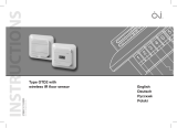
Type ETO2
Controller for ice
and snow melting
English page 2
Deutsch page 11
Polski page 21
Русский page 31
57651D 02/11 (MBC)
© 2011 OJ Electronics A/S

Type ETO2 is an electronic controller for fully automatic,
economical ice and snow melting on outdoor areas and in
gutters. Ice forms due to a combination of low
temperature and moisture. ETO2 detects both
temperature and moisture, and the snow melting system
will usually only be activated if snow or ice is present.
ETO2 is suitable for controlling electric heating cables, or
water-based heating pipes.
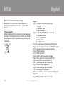
Product program
ETO2-4550-xxxx Thermostat.
ETOG-55-xxxxx Ground sensor for detecting
temperature and moisture.
ETOR-55-xxxxx Gutter sensor for detecting moisture.
ETF-744/99 Outdoor sensor for detecting
temperature
WARNING! – Read this manual!
Carefully read this instruction manual in its entirety,
paying close attention to all warnings listed below. Make
sure that you fully understand the use, displays and limi-
tations of the controller, because any confusion resulting
from neglecting to follow this instruction manual, or from
improper use of this device, may cause an installer to
commit errors, that may lead to ice & snow conditions
resulting in serious injury or death.
WARNING! – Be aware that snow, ice and
iceicles may be present even if you follow the
instruction or manual.
You are strongly advised to follow any unexpected build-
up of snow, ice layers or icicles. As an additional safety
measure, you should always perform a manual inspection
of public areas in order to secure safety for access of the
controlled areas.
WARNING! – Important safety instructions.
Disconnect the power supply before carrying out
any installation or maintenance work on this control unit
and associated components. This control unit and
associated components should only be installed by a
competent person (i.e. a qualified electrician). Electrical
installation must be in accordance with appropriate
statutory regulations.
CE MARKING, FOR EU
OJ Electronics A/S hereby declares that the product is
manufactured in accordance with Council Directive
EnglishType ETO2
2
© 2011 OJ Electronics A/S - ® The OJ trademark is a registred trademark belonging to OJ Electronics A/S

2004/108/EC on electromagnetic compatibility (and
subsequent amendments) and Council Directive
2006/95/EEC on electrical equipment designed for use
within certain voltage limits.
Applied standards
ETO2-4550-EU28: CE marking LVD/EMC: EN60730-2-9
ETO2-4550-US28:CAN/CSA E 60730-2-9:01.
ETO2-4550-RU28:CE marking LVD/EMC: EN60730-2-9
The product may only be used if the complete installation
complies with current directives.
The product carries a manufacturer's warranty if installed
in accordance with these instructions and current
regulations.
If the product has been damaged in any way, e.g. during
transport, it must be inspected and checked by
authorised personnel before being connected to the
power supply.
Technical data
Thermostat ETO2-4550:
Designed to be mounted indoor only!
Supply voltage . . . . . . . . . .115/240V AC ±10%, 50-60 Hz
Built-in electronic power supply (SMPS) . . .24 V DC, 8 VA
3 output relays (potential-free contact, NO) . . . . .3 X 16 A
Alarm relay (potential-free contact, NO) . . . . . . . .max. 5 A
Control signal to actuator (mixing valve) . . . . . .0-10 V DC
Supply voltage to actuator
(mixing valve) . . . . . . . . . . . . . . . . . . . . .24 V AC / 100 mA
On/off differential . . . . . . . . . . . . . . . . . . . . . .0.6°F / 0.3°C
Temperature range . . . . . . . . . . . . . .-4/+50°F / -20/+10°C
Ambient temperature . . . . . . . . . . . . . .32/122°F / 0/+50°C
Ambient air humidity . . . . . . . . . . . . . . . . . . . . . . .10-95%
Enclosure rating . . . . . . . . . . . . . . . . . . . . .IP 20 / Nema 1
Weight . . . . . . . . . . . . . . . . . . . . . . . . . . . . . . . . . .600 g
Dimensions H/W/D . . . . . . . . . . . . . . . . . . .90/156/45 mm
Type 1B
Control pollution degree 2
Rated impulse voltage . . . . . . . . . . . . . . . . . . . . . . . . .4 kV
Ground sensor type ETOG-55:
Designed to be embedded in outdoor areas.
Detection . . . . . . . . . . . . . . . . . .Moisture and temperature
Mounting . . . . . . . . . . . . . . . . . . . . . . . . . . . .Outdoor area
Enclosure rating . . . . . . . . . . . . . . . . . . . . . . . . . . . . .IP 68
Ambient temperature . . . . . . . . . .-57/+158°F / -50/+70°C
Dimensions . . . . . . . . . . . . . . . . . . . . . . . . . .H32, Ø60 mm
EnglishETO2
3
© 2011 OJ Electronics A/S

Gutter sensor type ETOR-55:
Designed to be mounted in gutter or downpipe. Is used
together with outdoor sensor type ETF.
Detection . . . . . . . . . . . . . . . . . . . . . . . . . . . . . . . .Moisture
Mounting . . . . . . . . . . . . . . . . . . . . . . .Gutter or downpipe
Enclosure rating . . . . . . . . . . . . . . . . . . . . . . . . . . . . .IP 68
Ambient temperature . . . . . . . . . .-57/+158°F / -50/+70°C
Dimensions H/W/D . . . . . . . . . . . . . . . . . . .105/30/13 mm
Outdoor sensor type ETF-744/99:
Detection . . . . . . . . . . . . . . . . . . . . . . . . . . . . .Temperature
Mounting . . . . . . . . . . . . . . . . . . . . . . . . . . . . . . . . . . .Wall
Ambient temperature . . . . . . . . . .-57/+158°F / -50/+70°C
Dimensions H/W/D . . . . . . . . . . . . . . . . . . . .86/45/35 mm
Water sensor type ETF-1899A:
Detection . . . . . . . . . . . . . . . . . . . . . . . . . . . . .Temperature
Mounting . . . . . . . . . . . . . . . . . . . . . . . . . . . .Strap on pipe
Ambient temperature . . . . . . . . . . .-4/+158°F / -20/+70°C
Dimensions H/W/D . . . . . . . . . . . . . . . . . . . .86/45/35 mm
The snow and ice melting system is deactivated in the
event of sensor failure.
SENSOR INSTALLATION
Ground sensor ETOG, fig. 1+3:
For installation on outdoor areas where snow and ice is a
regular problem. The sensor must be embedded
horizontally with its top flush with the surroundings. Use
the accompanying installation plate.
The sensor cable must be installed in accordance with
current regulations. We recommend that cable pipes be
laid to protect the sensor cable. Detailed installation
instructions are supplied with the sensor.
Gutter sensor ETOR, fig. 2+4:
For installation in a gutter, or downpipe on the sunny side
of the building. It is important to ensure that the sensor
contact elements face against the flow of melt water. If
necessary, two sensors can be installed in parallel.
Detailed installation instructions are supplied with the
sensor.
Note that the pink and grey wires are not used.
EnglishETO2
4
© 2011 OJ Electronics A/S

Outdoor sensor ETF-744/99, fig. 2+4:
ETF is for use with gutter sensor ETOR. ETF can also be
used separately for the detection of temperature alone.
The sensor should be mounted on the wall beneath the
eaves on the north side of the building.
Water sensor type ETF-1899A:
Only for use in waterbased system to detect temperature
in supply and return water. Must be fastened with strips
fixed directly on the pipe.
Sensor cables:
ETOG and ETOR are supplied with 10 m cable, which can
be extended up to approx. 200 m using standard
installation cable: 6x1.5 mm² for ETOG and 4x1.5 mm² for
ETOR. The ETF cable can be up to approx. 50 m in length.
Sensor cables must be installed in accordance with current
regulations. They must never be installed parallel to power
cables as electrical interference may distort the sensor
signal.
ETO2 installation
The unit is intended to be DIN-rail mounted in an
approved panel.
Wall mounting:
For USA and Canada: The thermostat can be wall-
mounted in a specially designed and UL-approved metal
box (accessory).
For other countries: The accompanying plastic cover can
be used for wall mounting in an indoor area.
Connect supply voltage to terminals N and L. All electrical
and mechanical installation must be performed in
accordance with applicable local regulations.
Setup:
• 1-zone electric heating control with ETOG (fig. 3+6):
Connect 1 or 2 ETOG sensors to terminals 11-20.
Connect heating cable to output relays 1, 2 and 3
according to fig. 8.
• 1-zone electric heating control with ETOR + ETF
(fig. 4+7):
Connect 1 or 2 ETOR sensors to terminals 11-20. Note
that the pink and grey wires are not used.
Connect 1 ETF sensor to terminals 31-32.
Connect heating cable to output relays 1, 2 and 3
according to fig. 8.
EnglishETO2
5
© 2011 OJ Electronics A/S

• 2-zone electric heating control with ETOG (fig. 6):
Connect 2 ETOG sensors to terminals 11-20.
Connect heating cable for zone 1 to output relay 1
according to fig. 8.
Connect heating cable for zone 2 to output relay 2
according to fig. 8.
• 2-zone electric heating control with ETOR (fig. 7):
Connect 2 ETOR sensors to terminals 11-20. Note that
the pink and grey wires are not used.
Connect heating cable for zone 1 to output relay 1
according to fig. 8.
Connect heating cable for zone 2 to output relay 2
according to fig. 8.
• 2-zone electric heating control with ETOR and
ETOG (fig. 5+6+7):
Connect 1 ETOR sensor to terminals 11-16 as sensor
1. Note that the pink and grey wires are not used.
Connect 1 ETOG sensor to terminals 11-20 as sensor
2. Connect heating cable for zone 1 (roof) to output
relay 1 according to fig. 8.
Connect heating cable for zone 2 (ground) to output
relay 2 according to fig. 8.
• 1-zone electric heating control and output control
(Y/∆) (fig. 9+10):
Advanced 2-step control with ETOG-55. 1/3 power on
heating cables in afterrun.
Connect 1 or 2 ETOG sensors to terminals 11-20.
Connect external contactor/relays to output relays 1, 2
and 3 according to fig. 10.
• 1-zone hydronic heating control for control of
supply water temp. with mixing valve (fig. 6+11):
Connect 1 or 2 ETOG sensor to terminals 11-16.
Connect supply voltage (24 V AC) for mixing valve to
terminals 25-26 (fig. 13)
Connect mixing valve to terminals 21-24 (fig. 13).
Connect ETF 1899A supply and return sensors to
terminals 27-30.
Connect primary pump to output relay 1 according to
fig. 14.
Connect secondary pump to output relay 2 according
to fig. 14.
EnglishETO2
6
© 2011 OJ Electronics A/S

• 1/2-zone hydronic heating control, simple (fig.
6+12):
Connect 1 or 2 ETOG sensors to terminals 11-20.
Connect circulation pump for zone 1 to output relay 1
according to fig. 14.
If zone 2 is used, connect circulation pump for zone 2
to output relay 2 according to fig. 14.
Application setup as for 1/2-zone electric heating
control, see User Manual, Startup.
• Remote control (fig. 15):
The forced heat and standby functions can be remotely
controlled by wiring ETO2 to external buttons/relays
(normally open).
Connect external standby button to terminals 33-34.
Connect external forced heat button to terminals 35-36.
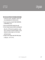
TESTING SNOW MELTING SYSTEM
After completing installation and application setup, it is
recommended that the snow melting system be tested.
1. Adjust SET TEMP in the setup menu to max.
temperature.
2. Pour some water onto the sensor (ETOG/ETOR).
3. The output relay for the heating cable in the zone
concerned should activate and ON should be
indicated on the ETO2 display. Check that the
heating cable becomes warm, check the voltage if
possible.
4. After testing, adjust SET TEMP back to the desired
setting (factory setting = +3.0°C / 37.4°F).
EnglishETO2
7
© 2011 OJ Electronics A/S

EnglishETO2
8
© 2011 OJ Electronics A/S
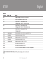
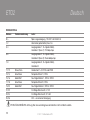
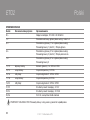
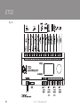
WIRING
Terminal Colour code Wiring
N, L Supply voltage, 120-240 V AC 50/60 Hz
1, 2 Alarm relay (potential free) max. 5 A
3, 4 Output relay 1, 16 A (potential free),
Heating cable 1 (zone 1) / Primary pump
5, 6 Output relay 2, 16 A (potential free),
Heating cable 2 (zone 2) / Secondary pump
7, 8 Output relay 3, 16 A (potential free),
Heating cable 3
11, 12 brown/green Sensor heating 1+2, ETOG 1+2 and ETOR 1+2
13, 14 grey/pink Temperature sensor, ETOG 1
15, 16 yellow/white Moisture sensor 1, ETOG 1/ ETOR 1
17, 18 grey/pink Temperature sensor, ETOG 2
19, 20 yellow/white Moisture sensor, ETOG 2 / ETOR 2
21, 22 3/4-way mixing valve, 0-10 V
23, 24 3/4-way mixing valve, 24 V AC
25, 26 24 V AC from external supply, for 3/4-way mixing valve
ETOR SENSOR WIRES : Note that the pink and grey wires are not used.
EnglishETO2

EnglishETO2
9
© 2011 OJ Electronics A/S
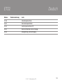
Terminal Colour code Wiring
27, 28 Supply water temperature sensor, ETF-1899A
29, 30 Return water temperature sensor, ETF-1899A
31, 32 Outdoor temperature sensor, ETF
33, 34 Standby, external input
35, 36 Forced control heat, external input
EnglishETO2

EnglishETO2
10
© 2011 OJ Electronics A/S
EnglishETO2
Environment protection and recycling
Help protect the environment by disposing of the
packaging and redundant products in a responsible
manner.
Product disposal
Products marked with this symbol must not be disposed
of along with household refuse, but must be delivered to a
waste collection centre in accordance with current local
regulations.
Figures
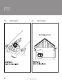
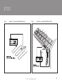
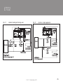
Fig. 1 Installation of ETOG ground sensor
1 Sensor
2 Installation plate
3 Heating element
Fig. 2 Installation of ETOR gutter sensor and
ETF outdoor sensor
1 Thermostat ETO2
2 Gutter sensor
3 Outdoor sensor
Fig. 3 One-zone electric heating with ETOG sensor
Fig. 4 One-zone electric heating with ETOR/ETF sensor
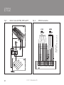
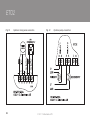
Fig. 5 Two-zone electric heating (roof/ground)
Fig. 6 ETOG connection
Fig. 7 ETOR connection
Fig. 8 Heating cable connection, example
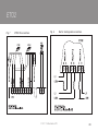
Fig. 9 Two-stage electric heating control (Y/∆)
Fig. 10 Advanced 2-step connection Y/∆
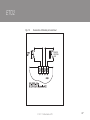
Fig. 11 Hydronic heating with mixing valve
Fig. 12 Simple hydronic application
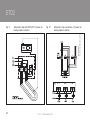
Fig. 13 Hydronic mixing valve connection
Fig. 14 Hydronic pump connection
Fig. 15 Connections for remote control of standby and
forced heat
Fig. 16 ETO2 controller, terminal overview

Typ ETO2 ist ein elektronischer Regler zur vollautomati-
schen, wirtschaftlichen Eis- und Schneeschmelze in
Außenbereichen und Dachrinnen. Eis bildet sich bei einer
bestimmten Konstellation von niedriger Temperatur und
Feuchtigkeit. ETO2 erfasst sowohl die Temperatur als auch
die Feuchtigkeit, und die Schneeschmelzanlage wird
gewöhnlich nur bei Vorhandensein von Schnee oder Eis
aktiviert. ETO2 eignet sich zum Regeln von elektrischen
Heizkabeln oder wasserbasierten Heizrohren.
Produktprogramm
ETO2-4550-xxxx Thermostat.
ETOG-55-xxxxx Bodenfühler zur Erfassung von Temperatur
und Feuchtigkeit.
ETOR-55-xxxxx Dachrinnenfühler zur Erfassung von
Feuchtigkeit
ETF-744/99 Außenfühler zur Temperaturerfassung
ACHTUNG - Bitte die Anleitung lesen!
Bitte die Bedienungsanleitung sorgfältig durchlesen
und die unten angeführten Sicherheitshinweise genau
beachten. Machen Sie sich mit dem Gebrauch, den
Anzeigen und den Begrenzungen der Steuerung völlig
vertraut, da aus der Nichtbeachtung dieser
Bedienungsanleitung oder unsachgemäßer Anwendung
dieses Geräts entstehende Unklarheiten zu Installations-
fehlern verleiten können, die verletzungs- oder lebensge-
fährliche Eis- und Schneebildung verursachen können.
ACHTUNG – Bitte beachten Sie, dass Schnee,
Eis und Eiszapfen selbst bei Einhaltung der
Anleitung auftreten können.
Es wird nachdrücklich empfohlen, jede unerwartete
Bildung von Schnee, Eisbelag oder Eiszapfen sorgfältig
zu beobachten. Als zusätzliche Sicherheitsmaßnahme
sollte in zugänglichen Bereichen immer eine persönliche
Inspektion vorgenommen werden, um sich vom gesicher-
ten Zustand des Kontrollbereichs zu überzeugen.
ACHTUNG – Wichtiger Sicherheitshinweis.
Vor Ausführung von Installations- oder Wartungs-
arbeiten an dieser Regeleinheit oder daran angeschlosse-
nen Komponenten ist die Stromversorgung immer abzu-
schalten. Diese Regeleinheit und die daran angeschlosse-
nen Komponenten dürfen nur von qualifizierten Elektrikern
installiert werden. Die Elektroinstallation muss in
Übereinstimmung mit den geltenden lokalen Regeln und
Vorschriften erfolgen.
DeutschETO2
11
© 2011 OJ Electronics A/S - ® OJ ist eine eingetragene Marke der OJ Electronics A/S

CE-KENNZEICHNUNG , INNERHALB DER EU
OJ Electronics A/S erklärt hiermit, dass das Produkt ent-
sprechend der Richtlinie des Rates 2004/108/EG (und nach-
träglichen Ergänzungen) über die elektromagnetische
Verträglichkeit (EMV) und der Richtlinie des Rates
2006/95/EG betreffend elektrische Betriebsmittel zur
Verwendung innerhalb bestimmter Spannungsgrenzen
(Niederspannungsrichtlinie) hergestellt ist.
Angewandte Normen
ETO2-4550-EU28: CE-Kennzeichnung NSR/EMV: EN60730-2-9
ETO2-4550-US28: CAN/CSA E 60730-2-9:01.
ETO2-4550-RU28: CE-Kennzeichnung NSR/EMV: EN60730-2-9
Das Produkt darf nur angewandt werden, wenn die gesamte
Anlage den aktuellen Richtlinien entspricht.
Für dieses Produkt wird vom Hersteller Garantie gewährleis-
tet, wenn es gemäß dieser Anleitung und den aktuellen
Richtlinien installiert wurde.
Wurde das Produkt in irgendeiner Weise beschädigt, z. B.
während des Transports, muss es vor dem Anschluss an die
Spannungsversorgung von autorisiertem Personal begut-
achtet und geprüft werden.
Technische Daten
Thermostat ETO2-4550:
Das Gerät ist nur für die Innenraum-Montage geeignet!
Netzspannung . . . . . . . . . . .115/240 V AC ±10 %, 50-60 Hz
Eingebaute elektronische
Stromversorgung (SMPS) . . . . . . . . . . . . . . . .24 V DC, 8 VA
3 Ausgangsrelais
(potentialfreier Kontakt, NO) . . . . . . . . . . . . . . . . . . .3 X 16 A
Alarmrelais (potentialfreier Kontakt, NO) . . . . . . . . .max. 5 A
Steuersignal zum Stellglied (Mischventil) . . . . . . .0-10 V DC
Betriebsspannung des Stellglieds
(Mischventil) . . . . . . . . . . . . . . . . . . . . . . .24 V AC / 100 mA
ON/OFF Abweichung . . . . . . . . . . . . . . . . . .0.6
°F / F0,3 °C
Temperaturbereich . . . . . . . . . . . . . . .-4/+50
°F / -20/+10 °C
Umgebungstemperatur . . . . . . . . . . . . .32/122
°F / 0/+50 °C
Umgebungsluftfeuchtigkeit . . . . . . . . . . . . . . . . . . .10-95 %
Schutzgrad . . . . . . . . . . . . . . . . . . . . . . . . . . .IP 20 / Nema 1
Gewicht . . . . . . . . . . . . . . . . . . . . . . . . . . . . . . . . . . . .600 g
Abmessungen H/B/T . . . . . . . . . . . . . . . . . . .90/156/45 mm
Typ 1B
Verschmutzungsgrad . . . . . . . . . . . . . . . . . . . . . . . . . . . . . . 2
Nennimpulsspannung . . . . . . . . . . . . . . . . . . . . . . . . . . . 4 kV
DeutschETO2
12
© 2011 OJ Electronics A/S

Bodenfühler, Typ ETOG-55:
Vorgesehen zum Einbetonieren in Außenbereichen.
Erfassung . . . . . . . . . . . . . . . . .Feuchtigkeit und Temperatur
Einbau . . . . . . . . . . . . . . . . . . . . . . . . . . . . . . . .Außenbereich
Schutzgrad . . . . . . . . . . . . . . . . . . . . . . . . . . . . . . . . . . .IP 68
Umgebungstemperatur . . . . . . . . . .-57/+158
°F / -50/+70 °C
Abmessungen . . . . . . . . . . . . . . . . . . . . . . . . .H32, Ø60 mm
Dachrinnenfühler, Typ ETOR-55:
Vorgesehen für Einbau in Dachrinne oder Abflussrohr.
Angewandt in Verbindung mit Außenfühler, Typ ETF.
Erfassung . . . . . . . . . . . . . . . . . . . . . . . . . . . . . .Feuchtigkeit
Einbau . . . . . . . . . . . . . . . . . . . . .Dachrinne oder Abflussrohr
Schutzgrad . . . . . . . . . . . . . . . . . . . . . . . . . . . . . . . . . . .IP 68
Umgebungstemperatur . . . . . . . . . .-57/+158
°F / -50/+70 °C
Abmessungen H/B/T . . . . . . . . . . . . . . . . . . .105/30/13 mm
Außenfühler Typ ETF-744/99:
Erfassung . . . . . . . . . . . . . . . . . . . . . . . . . . . . . . .Temperatur
Einbau . . . . . . . . . . . . . . . . . . . . . . . . . . . . . . .Wandmontage
Umgebungstemperatur . . . . . . . . . .-57/+158
°F / -50/+70 °C
Abmessungen H/B/T . . . . . . . . . . . . . . . . . . . .86/45/35 mm
Wasserfühler Typ ETF-1899A
Erfassung . . . . . . . . . . . . . . . . . . . . . . . . . . . . . . .Temperatur
Montage . . . . . . . . . . . . . . . . . . . . . . . . . . .Binder am Rohr
Umgebungstemperatur. . . . . . . . . . . .-4/158
°F / -20/+70 °C
Abmessungen H/B/T. . . . . . . . . . . . . . . . . . . .86×45×35 mm
Die Schnee- und Eisschmelzanlage wird im Falle von
Fühlerdefekt deaktiviert.
FÜHLERINSTALLATION
Bodenfühler ETOG, Abb. 1+3:
Zum Einbau in Außenbereichen, in denen Schnee und Eis
regelmäßig ein Problem darstellen. Der Fühler muss hori-
zontal mit dem Kopf fluchtend in den Boden eingelassen
werden. Die mitgelieferte Einbauplatte benutzen.
Das Fühlerkabel ist in Übereinstimmung mit den geltenden
Regeln und Vorschriften zu installieren. Wir empfehlen das
Verlegen von Kabelrohren, um das Fühlerkabel zu beschüt-
zen. Eine detaillierte Montageanweisung wird mit dem Fühler
mitgeliefert.
DeutschETO2
13
© 2011 OJ Electronics A/S

Dachrinnenfühler ETOR, Abb. 2+4:
Zum Einbau in der Dachrinne oder im Abflussrohr auf der
Sonnenseite des Gebäudes. Es ist sicherzustellen, dass die
Kontaktelemente des Fühlers entgegengesetzt der
Flussrichtung des Schmelzwassers angeordnet sind. Falls
erforderlich können zwei Fühler parallel installiert werden.
Eine detaillierte Montageanweisung wird mit dem Fühler mit-
geliefert.
Achtung: Der rosa und der graue Leiter dürfen nicht
installiert werden.
Außenfühler ETF-744/99, Abb. 2+4:
ETF ist mit dem Dachrinnenfühler ETOR zu benutzen. ETF
kann auch separat, nur zur Erfassung der Temperatur
benutzt werden. Der Fühler ist auf der Mauer unter dem
Dachüberhang auf der Nordseite des Gebäude zu montieren.
Wasserfühler Typ ETF-1899A
Anwendung nur in wasserbasierten Anlagen zur Erfassung
der Wasservorlauf- und -rücklauftemperatur. Ist mit Bindern
direkt am Rohr zu befestigen.
Fühlerkabel:
ETOG und ETOR sind mit 10 m langem Kabel ausgestattet,
das bis auf ca. 200 m verlängert werden kann, u. z. mit
Standardkabel 6x1,5 mm² für ETOG und 4x1,5 mm² für
ETOR (der Gesamtwiderstand darf 10 Ohm nicht überstei-
gen). Das ETF-Kabel kann bis auf ca. 50 m verlängert wer-
den. Fühlerkabel müssen in Übereinstimmung mit den gel-
tenden Regeln und Vorschriften installiert werden. Sie dür-
fen nicht parallel mit Starkstromkabeln verlegt werden, um
mögliche Störeinflüsse auf das Fühlersignal zu vermeiden.
ETO2 installation
Die Einheit ist für DIN-Schienenmontage in einer zugelasse-
nen Schalttafel vorgesehen. Die mitgelieferte Kunststoff-
abdeckung kann für Wandmontage in Innenbereichen
benutzt werden. Die Spannungsversorgung an den
Klemmen N und L anschließen. Die gesamte elektrische und
mechanische Installation muss in Übereinstimmung mit den
geltenden lokalen Regeln und Vorschriften erfolgen.
DeutschETO2
14
© 2011 OJ Electronics A/S

KONFIGURATION:
• 1-Zonen-Elektroheizungsregelung mit ETOG (Abb.
3+6):
Einen oder zwei ETOG-Fühler an die Klemmen 11-20
anschließen.
Heizkabel gem. Abb. 8 an die Ausgangsrelais 1, 2 und 3
anschließen.
• 1-Zonen-Elektroheizungsregelung mit ETOR + ETF
(Abb. 4+7):
Einen oder zwei ETOR-Fühler an die Klemmen 11-20
anschließen. Achtung: Der rosa und der graue Leiter dür-
fen nicht angeschlossen werden.
Einen ETF-Fühler an die Klemmen 31-32 anschließen.
Heizkabel gem. Abb. 8 an die Ausgangsrelais 1, 2 und 3
anschließen.
• 2-Zonen-Elektroheizungsregelung mit ETOG (Abb. 6):
Zwei ETOG-Fühler an die Klemmen 11-20 anschließen.
Heizkabel für Zone 1 gem. Abb. 8 an Ausgangsrelais 1
anschließen.
Heizkabel für Zone 2 gem. Abb. 8 an Ausgangsrelais 2
anschließen.
• 2-Zonen-Elektroheizungsregelung mit ETOR (Abb. 7):
Zwei ETOR-Fühler an die Klemmen 11-20 anschließen.
Achtung: Der rosa und der graue Leiter dürfen nicht
angeschlossen werden.
Heizkabel für Zone 1 gem. Abb. 8 an Ausgangsrelais 1
anschließen.
Heizkabel für Zone 2 gem. Abb. 8 an Ausgangsrelais 2
anschließen.
• 2-Zonen-Elektroheizungsregelung mit ETOR und
ETOG (Abb. 5+6+7):
Einen ETOR-Fühler als Fühler 1 an die Klemmen 11-16
anschließen. Achtung: Der rosa und der graue Leiter dür-
fen nicht angeschlossen werden.
Einen ETOG-Fühler als Fühler 2 an die Klemmen 11-20
anschließen.
Heizkabel für Zone 1 (Dach) gem. Abb. 8 an
Ausgangsrelais 1 anschließen.
Heizkabel für Zone 2 (Boden) gem. Abb. 8 an
Ausgangsrelais 2 anschließen.
DeutschETO2
15
© 2011 OJ Electronics A/S

• 1-Zonen-Elektroheizungsregelung und
Ausgangsschaltung (Y/∆) (Abb. 9+10):
Erweiterte 2-Stufen-Regelung mit ETOG-55. 1/3 Leistung
auf den Heizkabeln bei Nachheizung.
Einen oder zwei ETOG-Fühler an die Klemmen 11-20
anschließen.
Externen Schütz/externe Relais gem. Abb. 10 an die
Ausgangsrelais 1, 2 und 3 anschließen.
• 1-Zonen-Hydronic-Heizungssteuerung zur Regelung
der Vorlauftemp. mit Mischventil (Abb. 6+11):
Einen oder zwei ETOG-Fühler an die Klemmen 11-16
anschließen.
Versorgungsspannung (24 V~) für Mischventil an die
Klemmen 25-26 anschließen (Abb. 13).
Mischventil an die Klemmen 21-24 anschließen (Abb.
13).
ETF1899A-Vorlauf- und Rücklauffühler an die Klemmen
27-30 anschließen.
Hauptpumpe gem. Abb. 14 an das Ausgangsrelais 1
anschließen.
Hilfspumpe gem. Abb. 14 an das Ausgangsrelais 2
anschließen.
• Einfache 1/2-Zonen-Hydronic-Heizungssteuerung
(Abb. 6+12):
Einen oder zwei ETOG-Fühler an die Klemmen 11-20
anschließen.
Umwälzpumpe für Zone 1 gem. Abb. 14 an
Ausgangsrelais 1 anschließen.
Bei Anwendung von Zone 2, Umwälzpumpe für Zone 2
gem. Abb. 14 an Ausgangsrelais 2 anschließen.
Anwendungskonfiguration für 1/2-Zonen-
Elektroheizungsregelung, siehe Benutzerhandbuch,
Inbetriebnahme.
• Fernbedienung (Abb. 15):
Zwangsheizung und Bereitschaftsfunktion können mittels
Kabel vom ETO2 zu externen Tasten/Relais (normal
offen) ferngesteuert werden.
Die externe Bereitschaftstaste an die Klemmen 33-34
anschließen.
Die externe Zwangsheizungssteuerung an die Klemmen
35-36 anschließen.
ETO2
16
© 2011 OJ Electronics A/S
Deutsch

EnglishETO2
17
© 2011 OJ Electronics A/S
TEST DER SCHNEESCHMELZANLAGE
Nach Installation und Konfiguration wird empfohlen, die
Schneeschmelzanlage zu testen.
1. Die SET TEMP (Sollwerttemperatur) im Einstellmenü auf
max. Temperatur einstellen.
2. Etwas Wasser über den Fühler (ETOG/ETOR) gießen.
3. Das Ausgangsrelais für das Heizkabel der betreffenden
Zone sollte aktiviert und ON am ETO2-Display angezeigt
werden. Überprüfen, ob das Heizkabel warm wird, even-
tuell die Spannung messen.
4. Nach dem Test die SET TEMP wieder auf den
gewünschten Wert (Werkseinstellung = +3,0 °C/37,4 °F)
zurückstellen.
Deutsch

VERDRAHTUNG
Klemme Farbkennzeichnung Leiter
N, L Spannungsversorgung, 120-240 V AC 50/60 Hz
1, 2 Alarmrelais (potentialfrei) max. 5 A
3, 4 Ausgangsrelais 1, 16 A (potentialfrei),
Heizkabel 1 (Zone 1) / Primärpumpe
5, 6 Ausgangsrelais 2, 16 A (potentialfrei),
Heizkabel 2 (Zone 2) / Sekundärpumpe
7, 8 Ausgangsrelais 3, 16 A (potentialfrei),
Heizkabel 3
11, 12 Braun/Grün Heizelement 1+2, ETOG und ETOR
13, 14 Grau/Rosa Temperaturfühler 1, ETOG
15, 16 Gelb/Weiß Feuchtigkeitsfühler 1, ETOG / ETOR
17, 18 Grau/Rosa Temperaturfühler 2, ETOG
19, 20 Gelb/Weiß Feuchtigkeitsfühler 2, ETOG / ETOR
21, 22 3/4-Wege-Mischventil, 0-10 V
23, 24 3/4-Wege-Mischventil, 24 V AC
25, 26 24 V~ von externer Versorgung
ETOR-FÜHLERDRÄHTE: Achtung: Der rosa und der graue Leiter dürfen nicht installiert werden.
DeutschETO2
18
© 2011 OJ Electronics A/S

Klemme Farbkennzeichnung Leiter
27, 28 Vorlauftemperaturfühler
29, 30 Rücklauftemperaturfühler
31, 32 Außentemperaturfühler, ETF
33, 34 Bereitschaftsbetrieb, externer Eingang
35, 36 Zwangsheizung, externer Eingang
DeutschETO2
19
© 2011 OJ Electronics A/S

EnglishETO2
20
© 2011 OJ Electronics A/S
Umweltschutz und Recycling
Helfen Sie, die Umwelt zu schützen, und entsorgen Sie die
Verpackung und überschüssigen Teile
verantwortungsbewusst.
Entsorgung (Produkt)
Mit diesem Symbol gekennzeichnete Produkte dürfen nicht
gemeinsam mit Haushaltsabfall entsorgt werden, sondern
müssen entsprechend den lokalen Richtlinien bei einer
Abfallsammelstelle abgeliefert werden.
Abbildungen
Abb. 1 Installation des ETOG-Bodenfühlers
1 Fühler
2 Einbauplatte
3 Heizelement
Abb. 2 Installation von ETOR-Dachrinnenfühler und ETF
Außenfühler
1 Thermostat ETO2
2 Dachrinnenfühler
3 Außenfühler
Abb. 3 1-Zonen-Elektroheizung mit ETOG-Fühler
Abb. 4 1-Zonen-Elektroheizung mit ETOR/ETF-Fühler
Abb. 5 2-Zonen-Elektroheizung (Dach/Boden)
Abb. 6 ETOG-Anschluss
Abb. 7 ETOR-Anschluss
Abb. 8 Heizkabelanschluss, Beispiel
Abb. 9 2-Stufen-Elektroheizungsschaltung (Y/∆)
Abb. 10 Erweiterte 2-Stufen-Schaltung Y/∆
Abb. 11 Hydronic-Heizung mit Mischventil
Abb. 12 Einfache Hydronic-Anwendung
Abb. 13 Mischventilanschluss
Abb. 14 Wasserpumpenanschluss
Abb. 15 Anschluss für fernbediente Bereitschaftsfunktion
und Zwangsheizung
Abb. 16 ETO2-Regler Klemmenplan
Deutsch
Strona się ładuje...
Strona się ładuje...
Strona się ładuje...
Strona się ładuje...
Strona się ładuje...
Strona się ładuje...
Strona się ładuje...
Strona się ładuje...
Strona się ładuje...
Strona się ładuje...
Strona się ładuje...
Strona się ładuje...
Strona się ładuje...
Strona się ładuje...
Strona się ładuje...
Strona się ładuje...
Strona się ładuje...
Strona się ładuje...
Strona się ładuje...
Strona się ładuje...
Strona się ładuje...
Strona się ładuje...
Strona się ładuje...
Strona się ładuje...
Strona się ładuje...
Strona się ładuje...
Strona się ładuje...
Strona się ładuje...
Strona się ładuje...
Strona się ładuje...
Strona się ładuje...
Strona się ładuje...
-
 1
1
-
 2
2
-
 3
3
-
 4
4
-
 5
5
-
 6
6
-
 7
7
-
 8
8
-
 9
9
-
 10
10
-
 11
11
-
 12
12
-
 13
13
-
 14
14
-
 15
15
-
 16
16
-
 17
17
-
 18
18
-
 19
19
-
 20
20
-
 21
21
-
 22
22
-
 23
23
-
 24
24
-
 25
25
-
 26
26
-
 27
27
-
 28
28
-
 29
29
-
 30
30
-
 31
31
-
 32
32
-
 33
33
-
 34
34
-
 35
35
-
 36
36
-
 37
37
-
 38
38
-
 39
39
-
 40
40
-
 41
41
-
 42
42
-
 43
43
-
 44
44
-
 45
45
-
 46
46
-
 47
47
-
 48
48
-
 49
49
-
 50
50
-
 51
51
-
 52
52


w innych językach
- Deutsch: OJ ETO2
Powiązane artykuły
Inne dokumenty
-
WarmlyYours SCE-120 Economy Snow & Ice Melt Control Instrukcja instalacji
-
OJ Electronics ETO2-EU Instrukcja obsługi
-
-
OJ Electronics ETR2 Instrukcja obsługi
-
-
-
-
-
-
Grundfos PM 1 Installation And Operating Instructions Manual