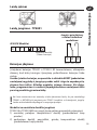
Danfoss TP5001 & TP5001-RF Instrukcja instalacji
- Kategoria
- Termostaty
- Typ
- Instrukcja instalacji

TP5001 Range
Installation Instructions
Instrukcja montażu
Montavimo instrukcijos
Інструкції зі
встановлення
Electronic 5/2 day programmable room thermostat
Mains, Battery and RF versions
GB
PL
LT
Uzstādīšanas instrukcijas
Montaj Yönergeleri
Návod na instalaci
UA
LV
TR
CZ

2
Installation Instructions
Important note RF products: Ensure that there are no large metal objects, such as boiler cases
or other large appliances, in line of sight between the transmitter and receiver as these will
prevent communication between thermostat and receiver.
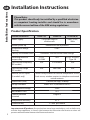
Product Speci cation
Please Note:
This product should only be installed by a quali ed electrician
or competent heating installer and should be in accordance
with the current edition of the IEEE wiring regulations.
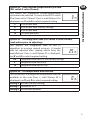
Thermostat features TP5001 (A) TP5001-RF TP5001M (A)
Power supply 2 x AA/MN1500/LR
alkaline cells
230V, ±15%,
50Hz
Memory back-up Retained for life of product
Temperature Range
Sensing
5-30°C
Factory set calendar clock Automatic summer/winter time change
Switching action of
output relay
3(1)A,
10-230V
N/A 3(1)A, 10-230V,
Type 1B
Transmission frequency
(RF models)
N/A 433.92MHz N/A
Transmission range
(RF models)
N/A 30m max. N/A
Remote sensor inputs
(A models only)
Can be set by installer for remote temperature sensor,
limit sensor, window contact or telephone activated
switch contacts
Dimensions (mm) 110 wide, 88 high, 28 deep
Design standard EN60730-2-9 (EN300220 for RF)
Rated impulse voltage 2.5kV
Ball hardness test 75°C
Control pollution
situation
Degree 2
Temperature accuracy ±1°C
Time accuracy ±1 min. per month
Installation Instructions
GB

3
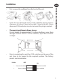
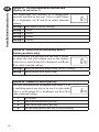
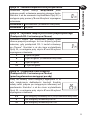
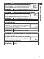
Installation
• First, remove the wallplate from the back of the unit.
• From the top left hand corner of the wallplate, there must be
clearances of at least 15mm to the right, 15mm to the left, 30mm
above and 100mm below in order to mount the plug-in module.
• Thermostat and Remote Room Sensor:
Fix at a height of approximately 1.5m from the oor, away from
draughts or heat sources such as radiators, open res or direct
sunlight.
• Prior to mounting the unit the 2 DIL switches on the rear of the
unit have to be moved to the required position. The factory
presets are shown below.
1
2
Keyboard disabled
Reset disabled Reset enabled
Keyboard enabled
OFF
ON
Sw. No.
Installation Instructions
GB

4
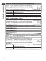
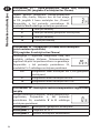
!
Some existing thermostats will have a Neutral and/or Earth wire connected. These
are not required by the TP5001 (battery models) and must NOT be connected to any
TP5001 terminals. Instead they should be made electrically safe and coiled in the
recess at the back of the TP5001.
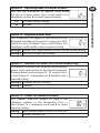
Cable Access
Wiring - TP5001
Models with remote sensor inputs
TP5001A and TP5001MA incorporate an input which can be used to
connect one of the following:
1) remote room temperature sensor (sold as accessory).
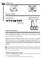
Battery Installation
When installing the batteries in the TP5001 and TP5001 RF please
ensure that the correct polarity is observed as per the markings on the
inside of the battery compartment.
Important: After installing the batteries press and release the RESET
button to start the unit. The display may appear blank until this is
done. Once the button is released the display will appear. All date, time,
programming and override settings are maintained for the life of the
product.
1
2
3
Output Connections,
all hard wired models
L
N
DE
S1 S2
Remote Sensor
(A version only)
M 230V Models
Installation Instructions
GB

5
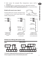
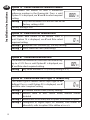
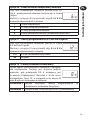
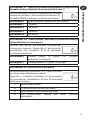
Models with remote sensor inputs
Terminal block for remote control/sensing
is located on the circuit board above the
battery compartment.
RX1
RX2 & RX3
12
3
4
ELECTRONICS
N
L
COM
ZONE
1 ON
ZONE
1 OFF
A
ELECTRONICS
B
C1
2
345
6
N
L
ZONE
1 ON
ZONE
1 OFF
ZONE
2 ON
ZONE
3 ON
COM
TERMINAL 6
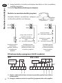
RX3 ONLY
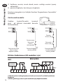
RX Receiver Wiring (RF models only)
1) For mains voltage operated systems link terminal 2 to mains live supply.
2) Power supply to unit must not be switched by timeswitch.
S1/D
S2/E
S1/D
S2/E
Window or
teleswitch
contact
(NO or NC)
Teleswitch
contact (NC)
Window
contact (NC)
S1/D
S2/E
Con gured for
remote room
sensor or limit
sensor
Con gured for
window contact or
other contact such
as teleswitch
Con gured for
window contact
and other contact
such as teleswitch
/D
/E
Remote
control
connections
2) limit sensor, for example, oor temperature sensor (sold as
accessory).
3) window contacts, card reader contacts or teleswitch contacts.
See Installer Advanced Programming Options for set-up instructions.
Installation Instructions
GB

6
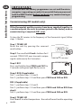
Commissioning (RF models only)
If the thermostat and the receiver have been supplied together in
a combined pack, the units have been paired in the factory and no
commissioning is required (RX1 only).
To tune the RX receiver to the frequency of the thermostat signal, follow
steps 1-5 below.
Step 1 TP5001-RF
Reset the unit by pressing the recessed
reset button.
Step 2 Press and hold V and + buttons for 3
seconds (TP5001-RF now transmits unique
signal continuously for 3 minutes).
Step 3 RX1
Press and hold buttons PROG and CH1 for
3 seconds until green light ashes once.
Step 4 RX2 (if applicable)
Stat 1 - perform steps 1-3 and 5.
Stat 2 - perform steps 1-2 and then press PROG and CH2 on RX2.
RX3 (if applicable)
Stat 1 - perform steps 1-3 and 5.
Stat 2 - perform steps 1-2 and then press PROG and CH2 on RX3 then
step 5.
Stat 3 - perform steps 1-2 and then press PROG and CH3 on RX3.
Step 5 TP5001-RF
Press V or Λ to select temperature - the unit will revert back to operating
mode.
IMPORTANT
To ensure that the factory programmes are set and the micro-
computer is operating correctly it is essential that you press and
hold the RESET button before you begin any commissioning or
programming.
Installation Instructions
GB

7
Installer advanced
programming options
TP5001 incorporates a number of advanced features which can be
set by the user. These are accessed via a User Advanced Programming
Mode, please refer to User Advanced Programming in the user
instructions for details.
Installer advanced programming options
TP5001 incorporates an additional number of advanced features which
can be set by the installer to improve the operating e ciency of the
system and where required, to change the user functionality of the
product. These are accessed via an Installer Advanced Programming
Mode. These settings are optional and need only be made if there is a
demand for the enhanced functions.
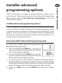
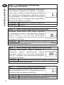
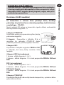
Entering Installer Advanced Programming mode
To access the Installer Advanced Programming
Mode follow the steps below:
a) Press and hold
V and PROG for 3 seconds to
enter User Advanced Programming, the display
will change to gure opposite.
b) Press and hold
V, Λ and PROG for 5 seconds
to enter Installer Advanced Programming, the
display will change to gure opposite.
c) Use + and - keys to scroll backwards and forwards between options
then
V and Λ keys to change the option settings. The ashing digit
on the right hand of the display indicates the number of the selected
option. The large characters display the option value selected.
d) To return to RUN, press and hold PROG until colon in the display
blinks.
Installation Instructions
GB

8
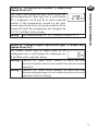
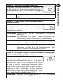
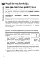
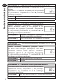
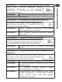
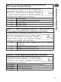
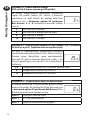
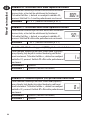
Option 30 - Set upper limit of temperature range
This allows the upper limit of the thermostat
setting range to be electronically limited. Press +
until Option 30 is displayed, use V and Λ to select
required setting.
Setting 40 - 5°C (Factory setting is 30°C)
Option 31 - Set lower limit of temperature range
This allows the lower limit of the thermostat
setting range to be electronically limited. Press +
until Option 31 is displayed, use V and Λ to select
required setting.
Setting 5 - 40°C (Factory setting is 5°C)
Option 32 - Enable O at lower limit
This enables an OFF function to be selected if a set
point below the lower limit is selected. Press + until
Option 32 is displayed, use
V and Λ to select required
setting.
Setting 0 Disabled
Setting 1 Enabled (factory setting)
Option 33 - Enable On at upper limit
This enables an ON function to be selected if a set
point above the upper limit is selected. Press + until
Option 33 is displayed, use
V and Λ to select required
setting.
Setting 0 Disabled (factory setting)
Setting 1 Enabled
Installation Instructions
GB

9
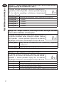
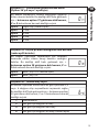
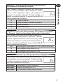
Option 34 - Select chrono-proportional cycle rate
(DIL switch 5 set to Chrono)
This allows the thermostat chrono-proportional
cycle rate to be selected. It is only active if DIL switch
5 has been set to “Chrono”. Press + until Option 34 is
displayed, use V and Λ to select required setting.
3 3 cycles per hour
6 6 cycles per hour (factory setting)
9 9 cycles per hour
12 12 cycles per hour
Option 35 - Set integration time (DIL switch 5 set to Chrono)
(seek advice prior to adjusting)
This adjusts the integration time of the PI
algorithm to increase control accuracy. It should
only be adjusted after seeking advice from the
manufacturer. Press + until Option 35 is displayed,
use V and Λ to select required setting.
2.5 Integration time set to 2.5% (factory setting)
5 Integration time set to 5%
10 Integration time set to 10%
Option 36 - Set temperature override rule
This establishes the degree of temperature override
available to the user. Press + until Option 36 is
displayed, use
V and Λ to select required setting.
Setting 0 No limit (factory setting)
Setting 1 Limited to ±2°C
Setting 2 No override allowed
Installation Instructions
GB

10
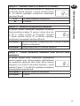
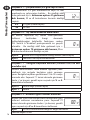
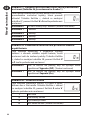
Option 38 - Relay state on low battery detect
(battery products only)
This establishes the position that the relay is driven
to when the unit shuts down due to low battery
state. Press + until Option 38 is displayed, use
V and
Λ to select required setting.
Setting 0 Relay parked with output OFF (factory setting)
Setting 1 Relay parked with output ON
Option 37 - Set time duration of override rule
(Option 36 set to 0 or 1)
This establishes the duration of a temperature
override available to the user. Press + until Option
37 is displayed, use V and Λ to select required
setting.
Setting 0 Next event (factory setting)
Setting 1 1 hour
Setting 2 2 hours
Setting 3 3 hours
Setting 4 4 hours
Option 40 - Number of Events per Day
This sets the thermostat to operate with either 2, 4 or
6 switching events per day or to run it in stat mode.
Press + until option 40 is displayed, use Λ or V to
select required setting.
1 Stat mode
2 Two switching events per day
4 Four switching events per day
6 Six switching events per day (Factory setting)
Installation Instructions
GB

11
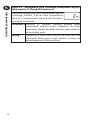
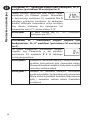
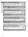
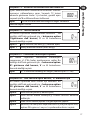
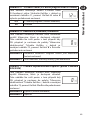
Option 70 - Keyboard disable rules
This establishes the degree of functionality of the
keyboard available to the user. It is only active if DIL
switch 6 is set to “Disabled”. Press + until Option 70 is
displayed, use V and Λ to select required setting.
Setting 0 Normal lock: Programming functions locked (factory setting)
Setting 1 Full lock: All keys are disabled
Option 71 - Random start rules (24V/230 Volt models only)
This enables a random start on power-up following a
power cut to reduce load on the electrical network.
Random delay is in the range of 2 - 90 seconds. Press
+ until Option 71 is displayed, use V and Λ to select
required setting.
Setting 0 Disabled (factory setting)
Setting 1 Enabled
Option 41 - Operating Mode (5/2 day or 24 hour)
This sets the thermostat to operate using either
5/2 day or 24 hour mode. Press + until option 41 is
displayed, use Λ or V to select required setting.
5-2 5/2 day (Factory setting)
24 24 hour
Option 72 - Owner site reference number
This enables multi-site owners to store a site
reference number in the thermostat. Press +
until Option 72 is displayed, use V and Λ to select
required setting.
Setting Any value between 00 and 99 can be set
Factory setting is 00
Installation Instructions
GB

12
Option 90 - De ne remote sensor type, “A” models only
This allows type of remote sensor input type to be
de ned. Press + until Option 90 is displayed, use V
and Λ to select required setting.
Setting 0 No remote sensor tted (Factory setting)
Setting 1 Remote room or duct sensor tted, internal sensor
disabled
Setting 2 Remote limit sensor tted, refer to option 93 to de ne set-point
Setting 3 Con gured as digital input for window, card reader or
teleswitch, refer to option 94 to de ne o/c or s/c.
Option 81 - Thermstat calibration bias
This allows the thermostat calibration to be biased by
up to ±1.5°K. Press + until Option 81 is displayed, use
V and Λ to select required setting.
Setting Any value between ±1.5 (Factory setting is 0°C)
Option 74 - Date format for calendar clock
This allows date format to be chosen. Press +
until Option 74 is displayed, use V and Λ to select
required setting.
Setting 0 European rules (dd/mm/yy), (Factory setting)
Setting 1 North American rules (mm/dd/yy)
Option 73 - Owner thermostat reference number
This enables site owners to store a thermostat
reference number in the thermostat. Press + until
Option 73 is displayed, use V and Λ to select required
setting.
Setting Any value between 000 and 999 can be set
Factory setting is 000
Factory setting is 000
Installation Instructions
GB

13
Option 93 - Set limit sensor set-point, “A” models only,
(option 90 set to 2)
This allows the thermostat limit sensor to be set,
typical application is oor htg. Press + until Option
93 is displayed, use V and Λ to select required
setting. If the temperature sensed by the limit
sensor exceeds the limit setting the output will be
turned o untill the temperature has dropped by
2°C “F10” will ash in the display.
Setting Any value between 20 - 50°C (Factory setting is 27°C)
Option 94 - Con gure digital input switch type, “A” models only,
(option 90 set to 3)
This allows switch type of digital input to be
con gured. Press + until Option 94 is displayed, use
V and Λ to select required setting.
Setting 0 Contacts NC, open circuit contact to force unit into
thermostat mode, short circuit contacts to return to normal
operation
Setting 1 Contacts NO, short circuit contacts to force unit into
thermostat mode, open circuit contacts to return to normal
operation (Factory setting)
Installation Instructions
GB

14
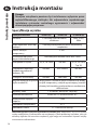
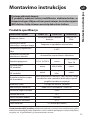
Instrukcja montażu
Ważna uwaga dot. wyrobów częstotliwości radiowej (RF): dopilnować, aby na linii wzroku
między nadajnikiem, a odbiornikiem nie znajdowały się duże przedmioty metalowe, takie jak
obudowy bojlerów lub inne duże urządzenia, gdyż mogą one uniemożliwić łączność między
termostatem a odbiornikiem.
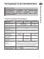
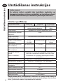
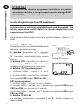
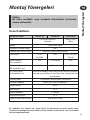
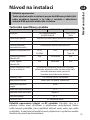
Specy kacja wyrobu
Uwaga:
Niniejsze urządzenie powinno być instalowane wyłącznie przez
wykwali kowanego elektryka lub odpowiednio wyszkolonego
instalatora systemów centralnego ogrzewania i odpowiadać
obowiązującym przepisom.
Funkcje termostatu TP5001 (A) TP5001-RF TP5001M (A)
Zasilanie 2 x AA/MN1500/LR baterie
alkaliczne
230V, ±15%,
50Hz
Kopia zapasowa (back-up)
pamięci
Zachowywana przez cały okres eksploatacji
urządzenia
Zakres odczytu
temperatury
5-30°C
Ustawienie fabryczne
zegara kalendarzowego
Automatyczna zmiana czasu lato / zima
Obciążalność styków 3(1)A, 10-230V Nie dot. 3(1)A, 10-230V,
Typ 1B
Częstotliwość transmisji
(modele częstotliwości
radiowej - RF)
Nie dot. 433,92MHz Nie dot.
Odległość komunikacji Nie dot. 30m max Nie dot.
Wejścia zdalnych czujników
(tylko modele A)
Mogą zostać ustawione przez instalatora na zdalny
czujnik temperatury, czujnik ograniczający, kontakt
okienny lub kontakty przełącznikowe uruchamiane
telefonicznie
Wymiary (mm) 110 szeroki, 88 wysoki, 28 gruby
Standard wzornictwa EN60730-2-9 (EN300220 dla RF)
Znamionowe napięcie
impulsu
2,5kV
Dokładność temperatury ±1°C
Dokładność czasu +/- 1 minuta na miesiąc
Instrukcja montażu
PL

15
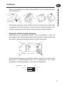
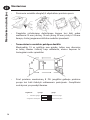
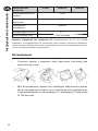
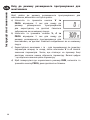
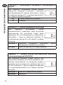
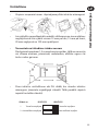
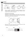
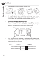
Instalacja
• W pierwszej kolejności należy zdjąć płytkę ścienna znajdującą się z
tyłu urządzenia.
• Od lewego górnego rogu płytki ściennej powinny być prześwity
co najmniej 15mm na prawo, 15mm na lewo, 30mm do góry oraz
100mm poniżej, aby można było zamontować moduł wtykowy.
• Termostat i zdalny czujnik pokojowy:
Zamontować na wysokości około 1,5m od podłogi, z dala od
przeciągów lub źródeł ciepła takich jak kaloryfery, otwarte kominki
lub miejsc, gdzie pada bezpośrednie światło słoneczne.
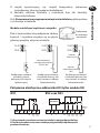
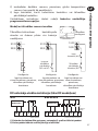
• Przed zamontowaniem urządzenia należy ustawić we właściwych
pozycjach 8 przełączników typu DIL, znajdujących się z tyłu
urządzenia. Poniżej pokazane są ustawienia fabryczne.
6
8
Klawiatura wł.
Reset
Wł./Wył.
Klawiatura wył.
Wył.
Wł.
Nr przełącznika
Instrukcja montażu
PL

16
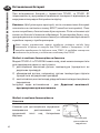
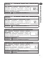
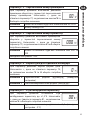
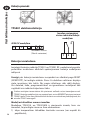
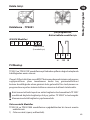
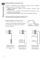
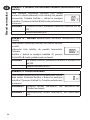
Instalacja baterii
Podczas instalacji baterii w termostatach TP5001 i TP5001 RF
należy zapewnić zachowanie prawidłowej biegunowości zgodnie z
oznaczeniami wewnątrz schowka na baterie.
WAŻNE: Po wymianie baterii należy nacisnąć i zwolnić przycisk RESET
w celu zrestartowania urządzenia. Do chwili wykonania tej czynności
ekran może pozostawać pusty. Po zwolnieniu przycisku pojawi się
ekran. Wszystkie ustawienia daty, czasu, programowania i ustawień
ręcznych są zachowywane do końca okresu eksploatacyjnego
produktu.
!
1
2
3
Wył.
COM Wł.
W niektórych istniejących termostatach przewód zerowy i/lub uziemienia są
połączone. Nie są one potrzebne dla urządzenia TP5001 (modele zasilane na baterie)
i do żadnych końcówek TP5001 NIE wolno ich podłączać. Należy zabezpieczyć
izolacją i zwinąć we wgłębieniu znajdującym się z tyłu TP5001.
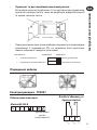
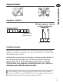
Podłączenie przewodów
Modele ze zdalnymi wejściami z czujnika
Modele termostatów TP5001A oraz TP5001MA wyposażone są
w wejście, które może być używane do podłączenia jednego z
następujących urządzeń:
1) zdalny czujnik temperatury pokojowej (sprzedawany jako
wyposażenie dodatkowe).
L
N
DE
S1 S2
Model M 230V
Zdalny czujnik
(tylko wersja A)
Przewody - TP5001
Wyjścia Połączeń,
wszystkie modele o stałych
połączeniach
Instrukcja montażu
PL

17
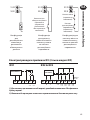
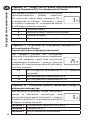
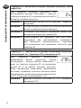
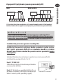
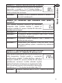
Modele ze zdalnymi wejściami z czujnika
Blok z końcówkami do podłączania zdalnej
kontroli / czujników znajduje się na płycie
głównej powyżej miejsca na baterie.
S1/D
S2/E
S1/D
S2/E
Kontakt okienny
lub teleprzełącznikowy
(NO lub NC)
S1/D
S2/E
Kontakt
teleprzełącznikowy
(NC)
Kontakt
okienny (NC)
Kon guracja zrobiona
na zdalny czujnik
pokojowy lub czujnik
ograniczający
Kon guracja zrobiona
na kontakt okienny lub
inny kontakt w rodzaju
teleprzełącznika
Kon guracja zrobiona
na kontakt okienny lub
inny kontakt w rodzaju
teleprzełącznika
/D
/E
Podłączenia
do zdalnego
sterowania
2) czujnik ograniczający, np. czujnik temperatury pokojowej
(sprzedawany jako wyposażenie dodatkowe).
3) kontakty okienne, kontakty z czytnikiem kart lub kontakty
teleprzełącznikowe.
Zob. Zaawansowane programowanie przez instalatora, gdzie podane
są instrukcje ustawienia.
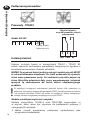
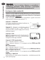
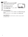
RX1
RX2 oraz RX3
12
3
4
ELECTRONICS
N
L
COM
ZONE
1 ON
ZONE
1 OFF
A
ELECTRONICS
B
C1
2
345
6
N
L
ZONE
1 ON
ZONE
1 OFF
ZONE
2 ON
ZONE
3 ON
COM
TERMINAL 6
RX3 ONLY
Połączenia elektryczne odbiornika RX (tylko modele RF)
1) W systemach na zasilanie sieciowe końcówkę 2 należy podłączyć do fazy.
2) Zasilanie urządzenia nie może w żadnym przypadku być włączane przez
przełącznik czasowy.
Instrukcja montażu
PL

18
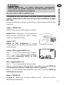
Dostrajanie (tylko modele RF)
Jeżeli termostat i odbiornik zostały dostarczone w jednym zestawie,
wówczas urządzenia te zostały dostrojone fabrycznie i dostrojenie
nie jest wymagane (tylko RX1).
Celem dostrojenia odbiornika RX do częstotliwości sygnału termostatu
należy wykonać wskazane niżej czynności 1-5.
Czynność 1 TP5001-RF
Zresetować urządzenie naciskając znajdujący się
we wgłębieniu przycisk reset.
Czynność 2 Nacisnąć i przytrzymać przez 3
sekundy przyciski V oraz + (teraz TP5001-RF
zaczyna wysyłać w sposób ciągły przez 3 minuty
unikatowy sygnał).
Czynność 3 RX1
Nacisnąć i przytrzymać przez 3 sekundy przyciski
PROG oraz CH1, aż do czasu jednorazowego
zamigotania zielonego światełka.
Czynność 4 RX2 (ewentualnie)
Stat 1 - wykonać czynności 1-3 oraz 5.
Stat 2 - wykonać czynności 1-2 a następnie nacisnąć PROG oraz CH2
na RX2.
RX3 (ewentualnie)
Stat 1 - wykonać czynności 1-3 oraz 5.
Stat 2 - wykonać czynności 1-2 a następnie nacisnąć PROG oraz CH 2 na
RX3, a następnie czynność 5.
Stat 3 - wykonać czynności 1-2 a następnie nacisnąć PROG oraz CH 3
na RX3.
Czynność 5 TP5001-RF
Nacisnąć V lub Λ celem wyboru temperatury – urządzenie powróci do
trybu operacyjnego.
WAŻNE
Żeby upewnić się, że nastawy fabryczne są prawidłowe i
funkcjonują poprawnie, należy przycisnąć i przytrzymać
przycisk RESET przed rozpoczęciem programowania.
Instrukcja montażu
PL

19
Opcje zaawansowanego
programowania przez
użytkownika
Termostat TP5001 wyposażony jest w szereg zaawansowanych funkcji,
które mogą być ustawiane przez użytkownika. Dostęp do tych funkcji
prowadzi przez tryb zaawansowanego programowania przez użytkownika,
zob. Zaawansowane Programowanie przez Użytkownika w instrukcji
użytkownika, gdzie podane są szczegółowe informacje na ten temat.
Opcje zaawansowanego programowania przez instalatora
Termostat TP5001 wyposażony jest w szereg dodatkowych
zaawansowanych funkcji, które mogą być ustawione przez instalatora
celem poprawy sprawności operacyjnej systemu oraz, tam gdzie jest to
potrzebne, celem zmiany funkcjonalności urządzenia dla użytkownika.
Dostęp do tych funkcji prowadzi przez tryb zaawansowanego
programowania przez instalatora. Ustawienia te mają charakter
opcjonalny i powinny być wprowadzane jedynie wówczas, jeżeli
faktycznie istnieje potrzeba ich użycia.
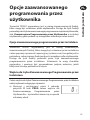
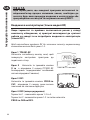
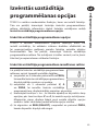
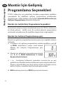
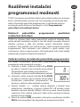
Wejście do trybu Zaawansowanego Programowania przez
Instalatora
Celem wejścia do trybu Zaawansowanego Programowania przez Instalatora
należy wykonać następujące czynności:
a) Nacisnąć i przytrzymać przez 3 sekundy
przyciski V oraz PROG celem wejścia do
Zaawansowanego Programowania przez
Użytkownika – wyświetlacz zmieni się w sposób
wskazany obok.
Instrukcja montażu
PL

20
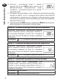
b) Nacisnąć i przytrzymać przez 5 sekund
przyciski V, Λ oraz PROG celem wejścia do
Zaawansowanego Programowania przez
Instalatora – wyświetlacz zmieni się w sposób
wskazany obok
c) Posługując się przyciskami + oraz – dokonywać przewijania między
opcjami w przód i w tył, a następnie przy pomocy przycisków V
oraz Λ zmienić ustawienia opcji. Migająca cyfra po prawej stronie
wyświetlacza pokazuje numer wybranej opcji. Duże litery pokazują
wybraną wartość opcji.
d) Celem powrotu do RUN nacisnąć i przytrzymać PROG aż do momentu,
kiedy dwukropek na wyświetlaczu zacznie migać.
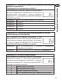
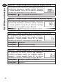
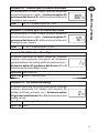
Opcja 30 – Ustawienie górnego limitu zakresu temperatury
Umożliwia elektroniczne ograniczenie górnego
limitu ustawienia zakresu termostatu. Naciskać +
do momentu pokazania się Opcji 30, a następnie
przy użyciu V oraz Λ dokonać wyboru żądanego
ustawienia.
Ustawienie 40 - 5°C (ustawienie fabryczne wynosi 30°C)
Opcja 31 - Ustawienie dolnego limitu zakresu temperatury
Umożliwia elektroniczne ograniczenie dolnego
limitu ustawienia zakresu termostatu. Naciskać +
do momentu pokazania się Opcji 31, a następnie
przy użyciu V oraz Λ dokonać wyboru żądanego
ustawienia.
Ustawienie 5 - 40°C (ustawienie fabryczne wynosi 5°C)
Opcja 32 – Nastawianie wyłączania na niższym pułapie
Umożliwia wybór funkcji WYŁĄCZANIA jeżeli
wybrano punkt ustawienia poniżej dolnego limitu.
Naciskać + aż do momentu wyświetlenia Opcji 32, a
następnie przy pomocy V oraz Λ wybrać wymagane
ustawienie ustawienie.
Ustawienie 0 Zablokowane
Ustawienie 1 Aktywne (ustawienie fabryczne)
Instrukcja montażu
PL
Strona się ładuje...
Strona się ładuje...
Strona się ładuje...
Strona się ładuje...
Strona się ładuje...
Strona się ładuje...
Strona się ładuje...
Strona się ładuje...
Strona się ładuje...
Strona się ładuje...
Strona się ładuje...
Strona się ładuje...
Strona się ładuje...
Strona się ładuje...
Strona się ładuje...
Strona się ładuje...
Strona się ładuje...
Strona się ładuje...
Strona się ładuje...
Strona się ładuje...
Strona się ładuje...
Strona się ładuje...
Strona się ładuje...
Strona się ładuje...
Strona się ładuje...
Strona się ładuje...
Strona się ładuje...
Strona się ładuje...
Strona się ładuje...
Strona się ładuje...
Strona się ładuje...
Strona się ładuje...
Strona się ładuje...
Strona się ładuje...
Strona się ładuje...
Strona się ładuje...
Strona się ładuje...
Strona się ładuje...
Strona się ładuje...
Strona się ładuje...
Strona się ładuje...
Strona się ładuje...
Strona się ładuje...
Strona się ładuje...
Strona się ładuje...
Strona się ładuje...
Strona się ładuje...
Strona się ładuje...
Strona się ładuje...
Strona się ładuje...
Strona się ładuje...
Strona się ładuje...
Strona się ładuje...
Strona się ładuje...
Strona się ładuje...
Strona się ładuje...
Strona się ładuje...
Strona się ładuje...
Strona się ładuje...
Strona się ładuje...
Strona się ładuje...
Strona się ładuje...
Strona się ładuje...
Strona się ładuje...
Strona się ładuje...
Strona się ładuje...
Strona się ładuje...
Strona się ładuje...
Strona się ładuje...
Strona się ładuje...
Strona się ładuje...
Strona się ładuje...
-
 1
1
-
 2
2
-
 3
3
-
 4
4
-
 5
5
-
 6
6
-
 7
7
-
 8
8
-
 9
9
-
 10
10
-
 11
11
-
 12
12
-
 13
13
-
 14
14
-
 15
15
-
 16
16
-
 17
17
-
 18
18
-
 19
19
-
 20
20
-
 21
21
-
 22
22
-
 23
23
-
 24
24
-
 25
25
-
 26
26
-
 27
27
-
 28
28
-
 29
29
-
 30
30
-
 31
31
-
 32
32
-
 33
33
-
 34
34
-
 35
35
-
 36
36
-
 37
37
-
 38
38
-
 39
39
-
 40
40
-
 41
41
-
 42
42
-
 43
43
-
 44
44
-
 45
45
-
 46
46
-
 47
47
-
 48
48
-
 49
49
-
 50
50
-
 51
51
-
 52
52
-
 53
53
-
 54
54
-
 55
55
-
 56
56
-
 57
57
-
 58
58
-
 59
59
-
 60
60
-
 61
61
-
 62
62
-
 63
63
-
 64
64
-
 65
65
-
 66
66
-
 67
67
-
 68
68
-
 69
69
-
 70
70
-
 71
71
-
 72
72
-
 73
73
-
 74
74
-
 75
75
-
 76
76
-
 77
77
-
 78
78
-
 79
79
-
 80
80
-
 81
81
-
 82
82
-
 83
83
-
 84
84
-
 85
85
-
 86
86
-
 87
87
-
 88
88
-
 89
89
-
 90
90
-
 91
91
-
 92
92


Danfoss TP5001 & TP5001-RF Instrukcja instalacji
- Kategoria
- Termostaty
- Typ
- Instrukcja instalacji
w innych językach
Powiązane artykuły
-
Danfoss TP5001 & TP5001-RF Instrukcja instalacji
-
Danfoss TP5001, TP5001-RF & TP5001M Instrukcja instalacji
-
-
-
-
-
-
-
-