AAT NVIP-4DN5042V/IRH-2P Instrukcja obsługi
- Kategoria
- Kamery ochrony
- Typ
- Instrukcja obsługi

U s e r ’s m a n u a l
(s h ort form )
NVIP-4DN5042V/IRH-2P

NVIP-4DN5042V/IRH-2P User’s manual (short form) ver.1.1
All rights reserved © AAT Holding S.A.
2
IMPORTANT SAFEGUARDS AND WARNINGS
EMC (2004/108/EC) and LVD (2006/95/EC ) Directives
CE Marking
Our products are manufactured to comply with the requirements of the following directives and
national regulations implementing the directives:
Electromagnetic compatibility EMC 2004/108/EC.
Low voltage LVD 2006/95/EC with further amendment. The Directive applies to electrical
equipment designed for use with a voltage rating of between 50VAC and 1000VAC as well
as 75VDC and 1500VDC.
WEEE 2012/19/EU
Information on Disposal for Users of Waste Electrical and Electronic Equipment
This appliance is marked according to the European Directive on Waste Electrical and
Electronic Equipment (2012/19/EU) and further amendments. By ensuring this product is disposed of
correctly, you will help to prevent potential negative consequences for the environment and human
health, which could otherwise be caused by inappropriate waste handling of this product.
The symbol on the product, or the documents accompanying the product, indicates that this appliance
may not be treated as household waste. It shall be handed over to the applicable collection point for
used up electrical and electronic equipment for recycling purpose. For more information about
recycling of this product, please contact your local authorities, your household waste disposal service
or the shop where you purchased the product.
RoHS Directive 2011/65/EU
Out of concern for human health protection and friendly environment, we assure that our products
falling under RoHS Directive regulations, regarding the restriction of the use of hazardous substances
in electrical and electronic equipment, have been designed and manufactured in compliance with the
above mentioned regulations. Simultaneously, we claim that our products have been tested and do not
contain hazardous substances whose exceeding limits could have negative impact on human health or
natural environment.
Information
The device, as a part of professional CCTV system used for surveillance and control, is not designed
for self installation in households by individuals without technical knowledge.
The manufacturer is not responsible for defects and damages that result from improper or inconsistent
with user’s manual installation of the device in the system.

NVIP-4DN5042V/IRH-2P User’s manual (short form) ver.1.1
All rights reserved © AAT Holding S.A.
3
IMPORTANT SAFEGUARDS AND WARNINGS
WARNING!
THE KNOWLEDGE OF THIS MANUAL AND FULL VERSION OF THE MANUAL IS AN
INDISPENSIBLE CONDITION OF A PROPER DEVICE OPERATION. YOU ARE KINDLY
REQEUSTED TO FAMILIARIZE YOURSELF WITH THE MANUAL PRIOR TO INSTALLATION
AND FURTHER DEVICE OPERATION.
WARNING!
USER IS NOT ALLOWED TO DISASSEMBLE THE CASING AS THERE ARE NO USER-
SERVICEABLE PARTS INSIDE THIS UNIT. ONLY AUTHORIZED SERVICE PERSONNEL
MAY OPEN THE UNIT
INSTALLATION AND SERVICING SHOULD ONLY BE DONE BY QUALIFIED SERVICE
PERSONNEL AND SHOULD CONFORM TO ALL LOCAL REGULATIONS
1. Prior to undertaking any action please consult the following manual and read all the safety and
operating instructions before starting the device.
2. Please keep this manual for the lifespan of the device in case referring to the contents of this manual
is necessary;
3. All the safety precautions referred to in this manual should be strictly followed, as they have a direct
influence on user’s safety and durability and reliability of the device;
4. All actions conducted by the servicemen and users must be accomplished in accordance with the
user’s manual;
5. The device should be disconnected from power sources during maintenance procedures;
6. Usage of additional devices and components neither provided nor recommended by the producer is
forbidden;
7. You are not allowed to use the camera in high humidity environment (i.e. close to swimming pools,
bath tubs, damp basements);
8. Mounting the device in places where proper ventilation cannot be provided (e. g. closed lockers etc.)
is not recommended since it may lead to heat build-up and damaging the device itself as
a consequence;
9. Mounting the camera on unstable surface or using not recommended mounts is forbidden.
Improperly mounted camera may cause a fatal accident or may be seriously damaged itself. The
camera must be mounted by qualified personnel with proper authorization, in accordance with this
user’s manual.
10. Device should be supplied only from a power sources whose parameters are in accordance with
those specified by the producer in the camera technical datasheet. Therefore, it is forbidden to
supply the camera from a power sources with unknown parameters, unstable or not meeting
producer’s requirements;
Due to the product being constantly enhanced and optimized, certain parameters and functions
described in the manual in question may change without further notice. We strongly suggest visiting
the www.novuscctv.com website in order to access the newest full version of the manual.
Data included in the following user’s manual is up to date at the time of printing. AAT Holding S.A.
holds exclusive rights to modify this manual. The producer reserves the rights for device specification
modification and change in the design without prior notice.

NVIP-4DN5042V/IRH-2P User’s manual (short form) ver.1.1
All rights reserved © AAT Holding S.A.
4
TABLE OF CONTENTS ..................................................................................................... 4
1. FOREWORD INFORMATION ................................................................................... ..5
1.1. General Characteristics ........................................................................................ 5
1.2. Specification .................................................................................................... ...6
1.3. Camera dimension ........................................................................................... ...7
1.4. Package contents ............................................................................................... ...7
2. START-UP AND INITIAL IP CAMERA CONFIGURATION ................................. 8
2.1. Description of connectors and control tools ........................................................ 8
2.2 Mounting the camera ............................................................................................ 9
2.3. Focus and zoom adjustment .............................................................................. 10
2.4. Starting the IP camera ........................................................................................ 11
2.5. Initial configuration via the Web browser ......................................................... 12
3. NETWORK CONNECTION VIA WEB BROSWER ............................................... 13
3.1. Recommended PC specification for web browser ............................................. 13
3.2. Connection with IP camera via web browser ..................................................... 13
4. WWW INTERFACE - WORKING WITH IP CAMERA ......................................... 17
4.1. Displaying live pictures. ..................................................................................... 17
5. ELECTRIC CONNECTORS AND ACCESORIES ................................................. 19
5.1. Connecting power supply to the camera. .......................................................... 19
5.2. Camera control - RS-485. ................................................................................... 19
5.3. Connecting alarm input and output .................................................................... 19
5.4. SD card installation ........................................................................................... 20
6. RESTORING FACTORY DEFAULTS ..................................................................... 21
6.1. Restoring factory defaults by software means ................................................... 21
6.2. Restoring hardware defaults by hardware means ............................................... 21
TABLE OF CONTENTS

NVIP-4DN5042V/IRH-2P User’s manual (short form) ver.1.1
All rights reserved © AAT Holding S.A.
5
1. FOREWORD INFORMATION
1.1. General Characteristics
Imager resolution: 4.0 megapixels
Mechanical IR cut filter
IR operation capability
Min. Illumination from: 0.034 lx/F=1.4 (DSS),
Digital Slow Shutter (DSS)
Digital Noise Reduction (DNR)
Lens type: Auto iris DC, f=3 ~ 12mm F=1.4
Built-in IR illuminator, 12 LEDs
Privacy zones: 5
Compression: H.264, M-JPEG
Max video processing resolution 2688 x 1520
Double streaming: resolution, speed and quality defined individually for each video stream
RTP/RTSP protocol support for video transmission
Pre & post-alarm functions
Intelligent Analysis: tamper detection, object disappearance detection, line cross detection, zone
entrance detection, line cross detection, loiter, multi loiter, abnormal speed, converse, illegal
parking
Hardware motion detection
Built-in webserver: camera configuration through the website
MicroSD card support
1 alarm input and 1 alarm output
Wide range of responses to alarm events: e-mail with attachment, saving file on FTP server,
saving file on NAS, saving file on SD card
Network protocol support : ONVIF (2.2)/Profile S, HTTP, TCP/IP, IPv4/v6, UDP/IP, RTSP,
FTP, DHCP, NTP, PPoE, SMTP
Software: NMS (NOVUS MANAGEMENT SYSTEM) for video recording, live monitoring,
playback and remote IP devices administration
Built-in heater
Degree of protection IP66
IK10 Vandalproof
Power supply: 12VDC, 24VAC, PoE (Power over Ethernet)
FOREWORD INFORMATION

NVIP-4DN5042V/IRH-2P User’s manual (short form) ver.1.1
All rights reserved © AAT Holding S.A.
6
1.2. Specification
FOREWORD INFORMATION
Image
Image Sensor 4 MPX CMOS sensor 1/3” OV
Number of Effective Pixels 2688 (H) x 1520 (V)
Min. Illumination
0.07 lx/F1.4 - color mode,
0.034 lx/F1.4 - color mode (DSS),
0 lx (IR on) - B/W mode
Electronic Shutter auto/manual: 1/5 s ~ 1/20000 s
Digital Slow Shutter (DSS) up to 1/5 s
Wide Dynamic Range (WDR) yes
Digital Noise Reduction (DNR) 2D, 3D
Lens
Lens Type varifocal auto iris DC, f=3 ~ 12 mm/F1.4
Day/Night
Switching Type mechanical IR cut filter
Switching Mode auto, manual, time
Switching Level Adjustment yes
Switching Delay 0 ~ 180 s
Switching Schedule yes
Visible Light Sensor yes
Network
Stream Resolution
2688 x 1520, 2560 x 1440 (QHD), 2304 x 1296, 1920 x 1080 (Full HD), 1280 x 720 (HD), 704 x 576, 640 x 480
(VGA), 640 x 360, 352 x 288 (CIF), 320 x 240 (QVGA)
Frame Rate
20 fps for 2688 x 1520, 2560 x 1440 (QHD),
25 fps for 2304 x 1296,
30 fps for 1920 x 1080 (Full HD) and lower resolutions
Multistreaming Mode 2 streams
Video/Audio Compression H.264, MJPEG/G.711, RAW_PCM
Number of Simultaneous Connections max. 8
Bandwidth 15 Mb/s in total
Network Protocols Support HTTP, TCP/IP, IPv4/v6, UDP, FTP, DHCP, DNS, DDNS, NTP, RTSP, RTP, SMTP
ONVIF Protocol Support Profile S (ONVIF2.2)
Camera Configuration from Internet Explorer, Firefox, Chrome, Opera browser
Compatible Software NMS
Other functions
Privacy Zones 5
Motion Detection yes
Video Content Analysis (VCA)
tamper, abandoned object, object disappearance, line cross, zone entrance, double line cross, loiter, multi loiter,
abnormal speed, converse, illegal parking
Image Processing 180˚ image rotation, sharpening, mirror effect, corridor mode
Prealarm/Postalarm up to 5 MB/up to 86400 s
System Reaction to Alarm Events e-mail with attachment, saving file on SD card
IR LED
LED Number 12
Range 15 m
Angle 120°
Interfaces
Video Output BNC, 1.0 Vp-p, 75 Ohm - maintenance only
Audio Input/Output 1 x RCA/1 x RCA
Alarm Input/Output 1 (NO/NC)/1
Network Interface 1 x Ethernet - RJ-45 interface, 10/100 Mbit/s
Memory Card Slot microSD - capacity up to 64GB
Installation parameters
Dimensions (mm) 130 (Ф) x 112 (H)
Weight 0.87 kg
Degree of Protection IP 66 (details in the user’s manual)
Enclosure vandal proof IK10 impact rating aluminium, white poly-carbonate bubble
Power Supply PoE, 12 VDC/24 VAC
Power Consumption
5 W,
8 W (IR on),
10 W (IR and heater on)
Operating Temperature -25°C ~ 55°C
Built-in Heater/Fan yes/no

NVIP-4DN5042V/IRH-2P User’s manual (short form) ver.1.1
All rights reserved © AAT Holding S.A.
7
FOREWORD INFORMATION
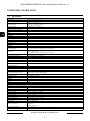
1.3. Camera dimensions
1.4. Package contents
After you open the package make sure that the following elements are inside:
IP camera
Accessories bag
RJ-45 Coupler
BNC Test Cable
Mounting template
Short version of user’s manual
CAUTION! We strongly suggest visiting the www.novuscctv.com website in order to access the
newest full version of the manual.
If any of these have been damaged during transport, pack all the elements back into the original box
and contact your supplier for further assistance.
CAUTION! If the device was brought from a location with lower temperature, please wait until
it reaches the temperature of location it is currently in. Turning the device on immediately after
bringing it from a location with lower ambient temperature is forbidden, as the condensing wa-
ter vapour may cause short-circuits and damage the device as a result.
Before starting the device familiarize yourself with the description and the role of particular
inputs, outputs and adjusting elements that the device is equipped with.

NVIP-4DN5042V/IRH-2P User’s manual (short form) ver.1.1
All rights reserved © AAT Holding S.A.
8
2. START-UP AND INITIAL IP CAMERA CONFIGURATION
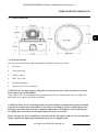
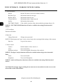
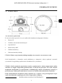
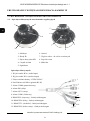
2.1. Description of connectors and control tools
START-UP AND INITIAL CAMERA CONFIGURATION
1. Lens
6. Focus
2. IR LED 7. BNC analog output - maintenance only
3. MicroSD card slot 8. Reset button
4. Light sensor
9. Microphone
5. Zoom
9
8
7
6
5
4
3
2 1
1
5
6
2
3
4
7
8
9
10
11
12
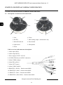
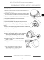
Cable overview with connectors description:
1. Audio input (RCA)
2. Audio output (RCA)
3. Power supply 12VDC / 24VAC
4. 100 Mb/s Ethernet port (RJ-45 connector)
5. Alarm COM0 (orange)
6. Alarm IN0 (yellow)
7. Alarm OUT1 (grey)
8. Alarm COM1 (purple)
9. RS485 RX+ (brown) - function unavailable
10. RS485 RX- (white) - function unavailable
11. RS485 TX+ (blue) - function unavailable
12. RS485 RX- (white-black) - function unavailable

NVIP-4DN5042V/IRH-2P User’s manual (short form) ver.1.1
All rights reserved © AAT Holding S.A.
9
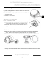
2.2. Camera mounting
1. Use the included allen key to remove the camera cover dome screws
and remove cover dome.
2. Use the included mounting template or the camera to mark holes for
the mounting screws.
3. Drill holes in marked places.
There are two ways to mount camera:
Method 1: Direct Attach Install
4a. Remove 2 of the 3 base locking screws. Use 2 pieces of M3x72
screws to mount the camera directly to the mounting surface.
5a. Remove the 3rd base locking screw and install the 3rd M3x72
screw.
Method 2: Camera Base Install
4b. Remove the camera base by unscrewing the 3 base locking screws, and turn camera module
approx. 5 degrees counterclockwise to detach camera base from the camera module.
5b. Install the base to the correct holes as indicated on the mount template using the M4x32 screws.
6. Ensure the rubber gasket inside the camera is properly in place, then mount the camera cover dome
and the camera cover screws.
START-UP AND INITIAL CAMERA CONFIGURATION

NVIP-4DN5042V/IRH-2P User’s manual (short form) ver.1.1
All rights reserved © AAT Holding S.A.
10
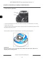
2.3 Zoom and focus adjustment
1. Use the included allen key to remove the camera cover dome screws and remove cover dome.
2. Adjust zoom and focus.
3. Ensure the rubber gasket inside the camera is properly in place, then mount the camera cover do-
me and the camera cover screws.
Camera module is placed on a mount allowing 3-axis module position adjustment.
WARNING!
Please pay attention to wires connecting camera module with camera body, while you are
adjusting camera module position.
START-UP AND INITIAL CAMERA CONFIGURATION
Zoom
Focus

NVIP-4DN5042V/IRH-2P User’s manual (short form) ver.1.1
All rights reserved © AAT Holding S.A.
11
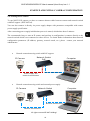
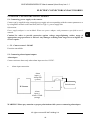
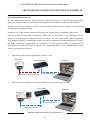
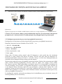
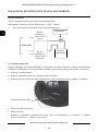
2.4. Starting the IP camera
To run NOVUS IP camera you have to connect ethernet cable between camera and network switch
with PoE support (IEEE 802.3af).
You can also connect it directly via power supply adapter with parameters compatible with camera
power supply specification.
After connecting power supply initialization process is started, which takes about 2 minutes.
The recommended way to start an IP camera and perform its configuration is connect directly to the
network switch which is not connected to other devices. To obtain further information about network
configuration parameters (IP address, gateway, network mask, etc.) please contact your network
administrator.
Network connection using switch with PoE support.
Network connection using switch and external power supply.
START-UP AND INITIAL CAMERA CONFIGURATION
Power supply and
network transmission
Computer IP Camera
Network Switch
PoE
Network transmission
IP Camera
Network transmission
Network Switch
Computer
Network transmission

NVIP-4DN5042V/IRH-2P User’s manual (short form) ver.1.1
All rights reserved © AAT Holding S.A.
12
Network connection using external power supply, directly to the computer.
Information:
Power supply adapter is not included. Please use power adapter with parameters specified in user’s
manual.
Caution:
In order to provide protection against voltage surges/lightning strikes, usage of appropriate surge
protectors is advised. Any damages resulting from surges are not eligible for service repairs.
2.5. Initial configuration via the web browser
The default network settings for NVIP-… IP camera series are :
1. IP address= 192.168.1.200
2. Network mask - 255.255.255.0
3. Gateway - 192.168.1.1
4. User name - root
5. Password - pass
Knowing the camera’s IP address you need to set PC IP address appropriately, so the two devices can
operate in one network subnet ( e.g. for IP 192.168.1.1, appropriate address for the camera is from
range 192.168.1.2 to 192.168.1.254, for example 192.168.1.60). It is not allowed to set the same
addresses for camera and PC computer
You can either set a network configuration (IP address, gateway, net mask, etc.) of NOVUS IP camera
yourself or select DHCP mode (DHCP server is required in this method in target network) by using
web browser or by NMS software. When you use DHCP server check IP address lease and its linking
with camera MAC address to avoid changing or losing IP address during device operation or network/
DHCP server breakdown. You have to remember to use a new camera IP address after changing
network parameters.
After network setting configuration has been done, the camera can be connected to a target network.
START-UP AND INITIAL CAMERA CONFIGURATION
IP Camera
Network transmission - cross over cable
Computer

NVIP-4DN5042V/IRH-2P User’s manual (short form) ver.1.1
All rights reserved © AAT Holding S.A.
13
3. NETWORK CONNECTION VIA WEB BROSWER
3.1. Recommended PC specification for web browser connections
Requirements below apply to connection with an IP camera, assuming image display in 1920x1080
resolution and 25 fps speed.
1. CPU Intel Pentium IV 3 GHz or faster
2. RAM Memory min. 512 MB
3. VGA card (any displaying Direct 3D with min. 128 MB RAM memory)
4. OS Windows XP / VISTA
5. Direct X version 9.0 or newer
6. Network card 10/100/1000 Mb/s
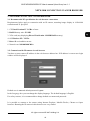
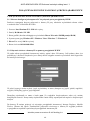
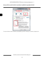
3.2. Connection with IP camera via web browser
You have to enter camera IP address in the web browser address bar. If IP address is correct user login
window will be displayed:
Default user is root and default password is pass.
In the Language box you can change the display language. The default language is English.
For safety reasons, it is recommended to change default user name and password.
It is possible to connect to the camera using Internet Explorer, Mozilla Firefox, Chrome or Opera
browsers. Running the IP camera in this browsers are very similar.
NETWORK CONNECTION VIA WEB BROWSER

NVIP-4DN5042V/IRH-2P User’s manual (short form) ver.1.1
All rights reserved © AAT Holding S.A.
14
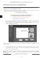
NETWORK CONNECTION VIA WEB BROWSER
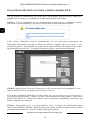
If your computer has Flash Player ins
t
a
ll
ed,
the main screen
for the
camera web interface
opens.
From here you can view and configure the
ca
m
e
ra
.
NOTE:
If your computer
does
not
have
Flash Player ins
t
a
ll
ed,
you will be prompted
t
o
select if
y
o
u
would like
t
o
use
Activ
eX
or Flash
Play
er
t
o
connect to the
ca
m
e
ra:
Click Click
here to shift playing life video with short delay widget! to
play
live
video
with
ActiveX
control
to
reduce
latency
(recommended): Uses
an
ActiveX
plug-in to connect to the camera. To
install the plug-in, click on the
video
area,
and
select Install
this
Add-on for all
users on this
computer,
and follow the
prompts.
NOTE:
Please open the Security settings of IE browser, and enable the Download unsigned
ActiveX controls.
Click
Please
download
the latest
version
of
Flash
Player to
play
live video:
Opens
a link to
download Flash Player from
Adobe’s
website.
After
completing the installation, restart your
browser and reconnect to the camera.
NOTE: When working in Windows Vista/7/8 the ActiveX applet may be blocked by Windows
Defender or User account control. In such case you should allow to run this applet, or simply disable
these functions.

NVIP-4DN5042V/IRH-2P User’s manual (short form) ver.1.1
All rights reserved © AAT Holding S.A.
15
NETWORK CONNECTION VIA WEB BROWSER
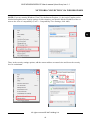
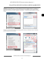
NOTE: If you are running Windows Vista/7/8 with Internet Explorer 11, the ActiveX applet can be
blocked through browser security settings. In this situation, you should: add the IP address of the ca-
mera to the view of compatibility (Tools -> Compatibility View Settings, click Add).
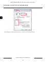
Then, in the security settings options, add the camera address to trusted sites and lower the security
level to a minimum.

NVIP-4DN5042V/IRH-2P User’s manual (short form) ver.1.1
All rights reserved © AAT Holding S.A.
16
NETWORK CONNECTION VIA WEB BROWSER
After making the changes, restart the browser, re-connect to the camera and log on.

NVIP-4DN5042V/IRH-2P User’s manual (short form) ver.1.1
All rights reserved © AAT Holding S.A.
17
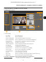
4. WWW INTERFACE - WORKING WITH IP CAMERA
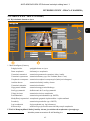
4.1. Displaying live pictures
1. Camera settings
Live Video - Live video preview
Device Info - Device information
Stream Configuration - Video and audio settings for each stream
Device Configuration - Device configuration (e.g. Local Network, Date&Time)
External Device - External device configuration (function unavailable)
Intelligent Analysis - Settings of video analysis
Alarm Configuration - Alarm Configuration (Motion alarm, Alarm I/O)
Local Record - Local Record Configuration
Privacy Masking - Configuration up to 5 privacy masks
Network Service - Network services configuration (e.g. DDNS)
Service Center - Service center configuration (e.g. SMTP)
Privilege Manager - Users and groups management
Protocol - Protocols settings (e.g. ONVIF)
Device Log - Device Log contains: Operation Log, Alarm Log and Collect Log
Maintenance - Device Restart and restoring Default Settings
CAUTION! Compatibility of analysis functions depends on recording device.
WWW INTERFACE - WORKING WITH IP CAMERA
3.
4.
1. 2.
5.

NVIP-4DN5042V/IRH-2P User’s manual (short form) ver.1.1
All rights reserved © AAT Holding S.A.
18
WWW INTERFACE - WORKING WITH IP CAMERA
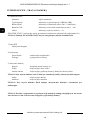
2. Video Parameter
Stream - Stream ID (choose one from available streams)
Bite Rate Type - Information about bit rate type
Bit Rate (kbps) - Information about bit rate
I Frame Interval - Information about I frame interval
Quality - Information about quality
USE TIME STAMP - Video buffer (increases delay when enabled, maximum delay is 5s)
NOTICE: USE TIME STAMP function will not be available when using Flash instead of
Activex.
3. PTZ configure
Function unavailable.
4. Menu bar
Change Password - Change users password
NOTICE: Default password "pass" can be restored only after restoring default settings of the camera)
Sign Out - Log out from camera
5. Video Control
Camera - Default number of the camera is 1.
Video - Turn on/off video
Inteligent Analysis - Turn on/off graphic illustration of the analysis.
NOTICE: Inteligent Analysis functions will not be available when using Activex instead of
Flash.
Audio - Turn on/off audio
Interphone - Turn on/off Interphone
NOTICE: Audio and Interphone functions will not be available when using Flash instead of
Activex.
CAUTION! We strongly suggest visiting the www.novuscctv.com website in order to access the
newest full version of the manual.

NVIP-4DN5042V/IRH-2P User’s manual (short form) ver.1.1
All rights reserved © AAT Holding S.A.
19
ELECTRIC CONNECTORS AND ACCESORIES
5. ELECTRIC CONNECTORS AND ACCESORIES
5.1. Connecting power supply to the camera.
Camera can be supplied using external power supply unit corresponding with the camera parameters or
by using RJ45 network socket and PoE (802.3at Type 1 ) power supply unit.
Information:
Power supply adapter is not included. Please use power adapter with parameters specified in user’s
manual.
Caution! In order to provide protection against voltage surges/lightning strikes, usage of
appropriate surge protectors is advised. Any damages resulting from surges are not eligible for
service repairs.
5.2. Camera control - RS-485
Function unavailable.
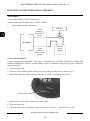
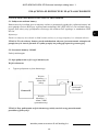
5.3. Connecting alarm inputs/outputs.
Alarm input
Camera activates alarm only when alarm input receives 12VDC.
Alarm input connection
WARNING! Please pay attention to proper polarization while you are connecting alarm input.
Alarm
input (-)
Alarm COM0
(orange)
IP Camera
Alarm
input (+)
Alarm IN0
(yellow)
Switch/sensor
_
+

NVIP-4DN5042V/IRH-2P User’s manual (short form) ver.1.1
All rights reserved © AAT Holding S.A.
20
ELECTRIC CONNECTORS AND ACCESORIES
Alarm output
Camera alarm output is an relay output type.
Alarm output relay maximum load: 12 VDC / 300mA.
Alarm output electric connections
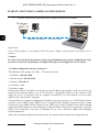
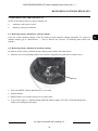
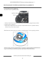
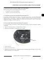
5.4 SD card installation
Camera supports microSD/SDHC cards up to a maximum size of 64GB. SanDisk™ or Kingston™
brand microSD/SDHC cards are recommended. In order to install the card properly, please follow the
instructions below:
Turn the camera off
Unscrew screws holding camera dome cover using allen key and remove camera cover.
Mount SD card in the socket located at the camera’s base, according to the picture:
Mount camera cover dome and screw to camera base.
Turn the camera on
Check the SD card by checking its capacity in the Local Record -> Record Directory tab.
Alarm
Output (-)
Alarm COM1
(purple)
Alarm
Output (+)
Alarm OUT1
(grey)
Indicator
power
supply
Indicator
IP Camera
SD card slot
Strona się ładuje...
Strona się ładuje...
Strona się ładuje...
Strona się ładuje...
Strona się ładuje...
Strona się ładuje...
Strona się ładuje...
Strona się ładuje...
Strona się ładuje...
Strona się ładuje...
Strona się ładuje...
Strona się ładuje...
Strona się ładuje...
Strona się ładuje...
Strona się ładuje...
Strona się ładuje...
Strona się ładuje...
Strona się ładuje...
Strona się ładuje...
Strona się ładuje...
Strona się ładuje...
Strona się ładuje...
Strona się ładuje...
Strona się ładuje...
-
 1
1
-
 2
2
-
 3
3
-
 4
4
-
 5
5
-
 6
6
-
 7
7
-
 8
8
-
 9
9
-
 10
10
-
 11
11
-
 12
12
-
 13
13
-
 14
14
-
 15
15
-
 16
16
-
 17
17
-
 18
18
-
 19
19
-
 20
20
-
 21
21
-
 22
22
-
 23
23
-
 24
24
-
 25
25
-
 26
26
-
 27
27
-
 28
28
-
 29
29
-
 30
30
-
 31
31
-
 32
32
-
 33
33
-
 34
34
-
 35
35
-
 36
36
-
 37
37
-
 38
38
-
 39
39
-
 40
40
-
 41
41
-
 42
42
-
 43
43
-
 44
44


AAT NVIP-4DN5042V/IRH-2P Instrukcja obsługi
- Kategoria
- Kamery ochrony
- Typ
- Instrukcja obsługi
w innych językach
- English: AAT NVIP-4DN5042V/IRH-2P User manual
Powiązane artykuły
-
Novus NVIP-9DN2018V/IR-1P Instrukcja obsługi
-
-
-
-
-
-
-
-
-
Inne dokumenty
-
Novus NVIP-3SD-8200/30 Instrukcja obsługi
-
Canon VB-H45 Instrukcja obsługi
-
DeLOCK 96389 Karta katalogowa
-
Axis T8124-E Technical Manual
-
Grandstream GSC3610 Karta katalogowa
-
Grandstream GSC3615 Karta katalogowa
-
 Riva RC3202HD-6211(W) Instrukcja instalacji
-
Swann Black & White Dome Cam Instrukcja obsługi
-
Grandstream GXV3610 v2 series Karta katalogowa
-
