
InnovaMass
®
240i/241i
Foundation Fieldbus
Preliminary Instruction Manual
Foundation Fieldbus Specification for Models: 240i and 241i
Volumetric & Multivariable Mass Vortex Flow Meter
Part Number: IM240i/241i-FF
V1 December 2015

GLOBAL SUPPORT LOCATIONS: WE ARE HERE TO HELP!
CORPORATE HEADQUARTERS
5 Harris Court, Building L Monterey, CA 93940
Phone (831) 373-0200 (800) 866-0200 Fax (831) 373-4402
www.sierrainstruments.com
EUROPE HEADQUARTERS
Bijlmansweid 2 1934RE Egmond aan den Hoef
The Netherlands
Phone +31 72 5071400 Fax +31 72 5071401
ASIA HEADQUARTERS
Second Floor Building 5, Senpu Industrial Park
25 Hangdu Road Hangtou Town
Pu Dong New District, Shanghai, P.R. China
Postal Code 201316
Phone: + 8621 5879 8521 Fax: +8621 5879 8586
IMPORTANT CUSTOMER NOTICE- OXYGEN SERVICE
Sierra Instruments, Inc. is not liable for any damage or personal injury, whatsoever, resulting from the use of Sierra Instruments standard mass
flow meters for oxygen gas. You are responsible for determining if this mass flow meter is appropriate for your oxygen application. You
are responsible for cleaning the mass flow meter to the degree required for your oxygen flow application.
© COPYRIGHT SIERRA INSTRUMENTS 2015
No part of this publication may be copied or distributed, transmitted, transcribed, stored in a retrieval system, or translated into any
human or computer language, in any form or by any means, electronic, mechanical, manual, or otherwise, or disclosed to third parties
without the express written permission of Sierra Instruments. The information contained in this manual is subject to change without
notice.
TRADEMARKS
InnovaMass
®
is a trademark of Sierra Instruments, Inc. Other product and company names listed in this manual are trademarks or trade
names of their respective manufacturers.

Warnings and Cautions
Warning!
Agency approval for hazardous location installations varies between flow meter models. Consult the flow meter
nameplate for specific flow meter approvals before any hazardous location installation.
Warning!
Hot tapping must be performed by a trained professional. U.S. regulations often require a hot tap permit. The
manufacturer of the hot tap equipment and/or the contractor performing the hot tap is responsible for providing proof of such a
permit.
Warning!
All wiring procedures must be performed with the power off.
Warning!
To avoid potential electric shock, follow National Electric Code safety practices or your local code when wiring this unit
to a power source and to peripheral devices. Failure to do so could result in injury or death. All AC power connections must be in
accordance with published CE directives.
Warning!
Do not power the flow meter with the sensor remote (if applicable) wires disconnected. This could cause over-heating of the
sensors and/or damage to the electronics.
Warning!
Before attempting any flow meter repair, verify that the line is de-pressurized.
Warning!
Always remove main power before disassembling any part of the mass flow meter.
Caution!
Before making adjustments to the device, verify the flow meter is not actively monitoring or reporting to any master
control system. Adjustments to the electronics will cause direct changes to flow control settings.
Caution!
All flow meter connections, isolation valves and fittings for hot tapping must have the same or higher pressure rating
as the main pipeline.
Caution!
Changing the length of cables or interchanging sensors or sensor wiring will affect the accuracy of the flow meter.
You cannot add or subtract wire length without returning the meter to the factory for re-calibration.
Caution!
When using toxic or corrosive gases, purge the line with inert gas for a minimum of four hours at full gas flow
before installing the meter.
Caution!
The AC wire insulation temperature rating must meet or exceed 80°C (176°F).
Caution!
Printed circuit boards are sensitive to electrostatic discharge. To avoid damaging the board, follow these
precautions to minimize the risk of damage:
before handling the assembly, discharge your body by touching a grounded, metal object
handle all cards by their edges unless otherwise required
when possible, use grounded electrostatic discharge wrist straps when handling sensitive components

Warnings and Cautions
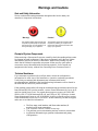
Note and Safety Information
We use caution and warning statements throughout this book to draw
your
attention to important information.
Warning!
Caution!
This statement appears with information that
is important to protect people and equipment
from damage. Pay very close attention to all
warnings that apply to your application.
This statement appears with information that is
important for protecting your equipment and
performance. Read and follow all cautions that
apply to your application.
Receipt of System Components
When receiving a Sierra mass flow meter, carefully check the outside
packing
carton
for damage incurred in shipment. If the carton is damaged, notify the local carrier
and submit a report to the factory or distributor. Remove the packing slip and
check that all ordered components are present. Make sure any spare parts or
accessories are not
discarded with the packing material. Do not return any
equipment to
the factory without first contacting Sierra Customer Service
.
Technical Assistance
If you encounter a problem with your flow meter, review the configuration
information for each step of the installation, operation, and
setup procedures.
Verify that your settings and adjustments are consistent with factory
recommendations.
Installation and troubleshooting information can be found in
the InnovaMass
®
240i/241i product manual.
If the problem persists after following the troubleshooting procedures
outlined in the
InnovaMass240i/241i product manual, contact Sierra Instruments by fax or by E-
mail
(see inside front cover). For urgent phone support you may call (800)
866-
0200 or (831) 373-0200 between 8:00 a.m. and 5:00 p.m. PST. In
Europe, contact
Sierra Instruments Europe at +31 20 6145810. In the Asia-Pacific region, contact
Sierra Instruments Asia at +
86-21-58798521.
When contacting Technical Support,
make sure to include this information:
The flow range, serial number, and Sierra order number (all
marked on the meter nameplate)
The software version (visible at start up)
The problem you are encountering and any corrective action
taken
Application information (gas, pressure, temperature and piping
configuration)

5
Table of Contents
Table of Contents .................................................................................................................................... 5
Chapter 1: Introduction .......................................................................................................................... 6
Chapter 2 – Connecting the 240i/241iSeries to Your FF-BUS Network .............................................. 7
Chapter 3 - Definitions ............................................................................................................................ 8
Chapter 4 – Foundation Fieldbus Interface Configurations ................................................................ 9
AI/AO Blocks: ....................................................................................................................................... 9
MODBUS_REGS_ (1 through 4): ......................................................................................................... 9
Chapter 5 – Configuring the FF-BUS Using NI-FBUS Configurator ................................................. 11
Getting Started Configuring FF-Bus Using NI-FBUS Configurator ..................................................... 11
Configuration ...................................................................................................................................... 11
MODBUS_COM_SETUP.................................................................................................................... 15
Chapter 6 – Available Modbus Registers ............................................................................................ 16
Chapter 7 – Modbus Registers Explained .......................................................................................... 19
Chapter 8 – Communication Diagnostic LEDS .................................................................................. 29

6
Chapter 1: Introduction
This manual will explain how to add a Sierra flow meter equipped with Foundation Fieldbus
to your network. The Foundation Fieldbus interface allows access to all relevant data
available in the flow meter.
This manual is intended to document the configuration of the Sierra Instruments’ InnovaMass
240i and 241i vortex mass flow meter with the Foundation Fieldbus Communication Interface
to your network. It assumes the reader already has a working knowledge of Foundation
Fieldbus. For specific operations of the Sierra Instruments’ 240i and 241i thermal flow
meters, consult the InnovaMass® 240i/241iSeries instruction manual.
For detailed information about Foundation Fieldbus go to: http://www.fieldbus.org/
The Sierra Instruments’ 240i/241iSeries mass flow meters can be ordered with the optional
Foundation Fieldbus (FF-BUS) Communication interface for use on a Foundation Fieldbus
H1 network. This Interface complies with the new ITK version 6.
FF-BUS differs from other digital communication protocols, it is designed for process control
rather than just transfer of data between a device and a central controller. It supports peer-to-
peer communication and allows for functional blocks to operate independently between
themselves without main controller intervention.
Foundation Fieldbus H1 networks are connected using a shielded twisted wire pairs. For
more information about FF-BUS H1 wiring see:
http://www.fieldbus.org/images/stories/enduserresources/technicalreferences/documents/wirin
ginstallationguide.pdf

7
Chapter 2 – Connecting the InnovaMass 240i/241i to
your FF-BUS Network
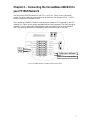
The InnovaMass 240i/241imeters use 24VDC (+/-10%) at 1.1 Amp. Due to the current
needed, the meter cannot be powered from the H1 network. The separate 24VDC (+/-10%)
power is connected to terminals 1 and 2.
The Foundation Fieldbus H1 network connections are labeled as FF-1(terminal 13 and FF-2
(terminal 14). These are not polarity dependent and will work reversed. The EMC ground on
terminal 15 can be connected to Earth ground or the wire shield if you are using shielded
wire. This can help eliminate Electromagnetic and Electrostatic noise on the data.
Figure 1. InnovaMass 240i/241i Foundation Fieldbus minimum wiring
FF-1
Terminal pin 1: DC Power +
Terminal pin 2: DC Power -
FF-2

8
Chapter 3 - Definitions
DD: Device Description files are necessary to configure your FF-BUS host software. The
DD files explain the specific configuration and features to your host network so it understands
how to use the device.
Resource Block (RS): This function block contains basic information about the FF-BUS
interface.
Transducer Block (TB): This block makes the connection to the meter and presents the
process variables to the lower blocks. Most of the configuration setup is done in this block.
AI (Analog Input) Block: Although this is actually digital process data coming from the
instrument (output), it is still referred to as an AI Block. This FF-BUS interface has four
analog input blocks: AI1, AI2, AI3, and AI4.
AO (Analog Output) Block: Although this is a digital command being sent to the instrument
(input), it is still referred to as an AO Block. The 240i/241iFF-BUS interface has one, labeled
AO.
Modbus: Modbus is another digital communication protocol and is only relevant here
because the Sierra FF-BUS interface uses Modbus as an intermediary between the meter and
the FF-BUS interface. For special configuration, the user will only need a rudimentary
knowledge of Modbus.
MODBUS_REG_SETUP_1 to 4: This is where AI1,2,3,4 and AO are configured as
PV1,2,3,4, and Final Value. These are 32-bit registers the can configured multiple data types
in various Byte order.
MODBUS_REGS_1 to 4: There are four groups of ten Modbus R/W registers that can be
used for static variables such as serial number, calibration date, total reset, and meter full
scale. These only have limited use, and may not be able to be seen with all FF-BUS devices.
32-bit float: Also known as Real or IEEE-754 single precision. The 32-bit float is a common
data encoding scheme that provides 1 bit for the sign, 8 bits for an exponent, and 23 bits of
significant numbers. In Modbus the Byte order is normally 1-0,3-2, however FF-BUS
interface allows it to be changed if needed.
16-bit short integer: This is a 16-bit number ranging from 0-65,535 (2
16
). The Byte order is
0,1.
32-bit long integer: This combines two 16-bit Modbus registers to make a number as high as
4,294,967,296 (2
32
). The Byte order is 1-0,3-2. The FF-BUS will see this as one 32-bit
integer.
String (Character): A 16-bit Modbus register would contain 2 ASCII characters (8 bits each)
in 0-1 Byte order. So ox 41 42 would equal “A B”.

9
Chapter 4 – Foundation Fieldbus configuration
The 240i/241iFF-BUS interfaces uses a Modbus to FF-BUS translator board inside the flow
meter. This allows the user to configure variables accessible to our Modbus interface. For the
most part, the Modbus to FF-BUS translation is invisible to the end user unless they want to
reconfigure the Transducer Block (TB) to access other Modbus variables.
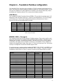
AI/AO Blocks:
The Foundation Fieldbus Transducer Block (SIERRA_TB) provides four analog inputs (AI1
through AI4) and one analog output (AO). These are all configurable as 16 or 32-bit integer
or Float data types. We have pre-configured these blocks as shown below in Table 1.
However, the user can reconfigure them as needed.
AI/AO
Blocks
Primary
Value
Channel
Data Type
Analog Signal
AI1
PV1
1
32-bit Float/Real
Flow Rate
AI2
PV2
2
32-bit Float/Real
Temperature
AI3
PV3
3
32-bit Float/Real
Pressure
AI4
PV4
4
32-bit Float/Real
Total
AO
Final Value
5
*
*
*Unassigned, open for customer configuration.
MODBUS_REGS_ (1 through 4):
The Transducer Block also has four groups of Modbus registers. These can be used for static
setup inputs and outputs for variables such as reading the Serial Number, Calibration Date or
changing the Gas Index, or resetting the totalizer. This data is not cyclic as it only updates
occasionally, and might not be accessible to all devices on the fieldbus. These variables are
limited to an unsigned short integer, Byte order 0-1. There are four groups of ten. Each group
can only be configured in consecutive Modbus register order.
To use these groups, a starting registers number (MODBUS_REG_START_ADDRESS) and
the number of registers after (NUM_OF_MODBUS_REG) is needed. These have been pre-
configured as shown below in Table 2. However, the user can reconfigure them as needed.
Variable
MODBUS_REGS
Group
REG_START
ADDRESS
NUM_OF_REGS
Alarm status
1
8
10
Gas name ASCII Char 1-2
Gas name ASCII Char 3-4
Gas name ASCII Char 5-6
Gas name ASCII Char 7-8
Gas name ASCII Char 9-10
Gas name ASCII Char 11-12
Gas name ASCII Char 13-14
Gas name ASCII Char 15-16
Gas index
Flow units ASCII Char 1-2
2
18
10
Flow units ASCII Char 3-4
Flow units ASCII Char 5-6
Flow units ASCII Char 7-8
Flow unit - index
User full scale – low word
User full scale – high word
Totalizer units Char 1-2
Table 1: Factory AI/AO Blocks

10
Totalizer units Char 3-4
Totalizer unit - index
Temp. units ASCII Char 1-2
3
28
7
Temperature unit - index
Pressure units ASCII Char 1-2
Pressure units ASCII Char 3-4
Pressure units ASCII Char 5-6
Pressure units ASCII Char 6-7
Pressure unit - index
Alarm active
4
61
2
Alarm mode
Table 2: Factory Static MODBUS Registers

11
Chapter 5 – Re-configuring the FF-BUS Using NI-
FBUS Configurator
The National Instruments F-BUS Configurator software is widely used for testing and
configuration of FF-BUS devices. Consult your NI-FBUS Configurator manual for more
information on this NI software (included in NI-FBUS help on the software).
Before starting the NI-FBUS Configurator, you must import the DD using the NI-FBUS
Interface Configurator Utility. The DD files are available can be downloaded from our web
site at: http://www.sierrainstruments.com/userfiles/file/Tested_Sierra_FF_DD_files.zip
Or from the Fieldbus Foundation web site at:
http://www.fieldbus.org/index.php?option=com_mtree&task=viewlink&link_id=1958&ffbsta
tus=Registered&Itemid=324
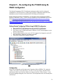
Getting Started Configuring FF-Bus Using NI-FBUS Configurator
1. Start the NI-FBUS COM manager then start the NI-FBUS Configurator.
2. When NI-FBUS Configurator starts, choose the FF-BUS interface used.
3. If the 240i or 241i is connected correctly, SIERRA_DEVICE should appear on your
screen as shown below.
4. The node address (factory set) is set to 247. We suggest it be changed to suit the FF-
BUS application. Change the Tag names as needed.
5. Make other configuration changes as needed.
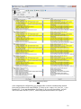
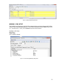
Configuration
Most of the configuration will be done in the Transducer Block (SIERRA_TB) under the
“Others” tab (see the screen shots below). In order to write any changes, the Block Mode
must be set to OOS (out of service). Make your changes and click “Write Changes.” Once
the yellow highlights disappear, click Auto mode. The configuration below was already done
at the factory.
Figure 2: NI Screen after SIERRA_DEVICE Is Found

12
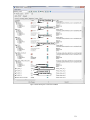
After completing the configuration, you should be able to read the variables being returned
from your flow meter on the same SIERRA_TB block on the “Others” tab. Flow (PV_1) and
Pressure (PV_2), etc. are shown below (See Figure 4). If you scroll down futher, you will
also see the static MODBUS_REGS_ values being read from the meter (See Figure 5).
Figure 3: Screen before Writing Changes

13
Current Temperature
Current Flow Rate
Figure 4 Screen Showing PV1,2,3,4 & Units From Meter
Current Pressure
Accumulated Total Flow
Flow Units
Temperature Units
Pressure Units
Total Flow Units

14
You may also set the engineering units in the NI-FBUS Configurator so they can be read by
the FF-BUS under PV_UNIT_1,2,3,4 and FINAL_VALUE_AO_UNIT (See Figure 6).
To change the engineering units the meter is using requires changing the flow units,
temperature unit, or pressure unit index in the Modbus registers.
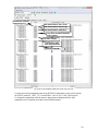
Fig. 5 Screen showing MODBUS_REGS static register values from meter
Alarm Status (ox0=off)
Gas Name in ASCII, ox41,72,=Ar
Gas Name in ASCII, ox67,6F =go
Gas Name in ASCII, ox6E,20 =n
The rest of the ASCII characters
ox20 = (space)
Gas Index 1=Argon
Flow Units in ASCII
ox53,43,46,5D=SCFM
Flow Index 1=SCFM

15
MODBUS_COM_SETUP
The Modbus com settings are needed for the communication connection between the Modbus
and the FF-BUS boards inside the meter. The Modbus Instrument Address must always be set
to 1. The MODBUS _COM_SETUP must always set as shown below:
BaudRate: 9600 Baud
Stop_Bits: 1
Parity: None
CRC_ORDER: Normal
Figure 7: Screen Showing MODBUS_COM_SETUP
Figure 6: TB Block Engineering Unit Setup

16
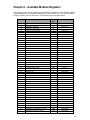
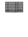
Chapter 6 – Available Modbus Registers
Although most users will be satisfied using the default configuration, other Modbus registers
can be configured for Foundation Fieldbus access. Below (Table 3) is a list of all available
Modbus registers. These would need to be configured in the transducer block.
Register
Description
Read/
Write
Data Type
00
Actual flow - low word
R
32 bits real
01
Actual flow - high word
R
02
Actual temp - low word
R
32 bits real
03
Actual temp - high word
R
04
Actual pressure - low word
R
32 bits real
05
Actual pressure - high word
R
06
Actual total - low word
R
32 bits real
07
Actual total - high word
R
08
Alarm status
R
integer
09
Gas name
R
16 bits , 2 ASCII per reg.
~
10
16 Characters total
17
Gas index
R/W
integer
18
Flow units
R
16 bits , 2 ASCII per reg.
~
21
8 Characters total
22
Flow unit - index
R/W
integer
23
User full scale – low word
R/W
32 bits real
24
User full scale – high word
R/W
25
Totalizer units
R
16 bits ASCII
26
27
Totalizer unit - index
R
integer
28
Temperature units
R
16 bits, 2 ASCII Char.
29
Temperature unit - index
R/W
integer
30
Pressure units
R
16 bits ASCII
~
33
8 Characters total
34
Pressure unit - index
R/W
16-bit integer
35
Standard Temperature - low word
R/W
32 bits real
36
Standard Temperature - high word
R/W
37
Standard Temperature - index
R/W
16-bit integer
38
Standard pressure - low word
R/W
32 bits real
39
Standard pressure - high word
R/W
40
Standard pressure - index
R/W
16-bit integer
41
Normal Temperature - low word
R/W
32 bits real
42
Normal Temperature - high word
R/W
43
Normal Temperature - index
R/W
16-bit integer
44
Normal pressure - low word
R/W
32 bits real
45
Normal pressure - high word
R/W
46
Normal pressure - index
R/W
16-bit integer
47
Adjust DAC for flow – 4mA
R/W
16-bit integer
48
Adjust DAC for flow – 20mA
R/W
16-bit integer
49
Adjust DAC for Temperature – 4mA
R/W
16-bit integer
50
Adjust DAC for Temperature – 20mA
R/W
16-bit integer
51
Adjust DAC for pressure – 4mA
R/W
16-bit integer

17
52
Adjust DAC for pressure – 20mA
R/W
16-bit integer
53
Temperature 4mA value – low word
R/W
32 bits real
54
Temperature 4mA value – high word
R/W
55
Temperature 20mA value – low word
R/W
32 bits real
56
Temperature 20mA value – high word
R/W
57
Pressure 4mA value – low word
R/W
32 bits real
58
Pressure 4mA value – high word
R/W
59
Pressure 20mA value – low word
R/W
32 bits real
60
Pressure 20mA value – high word
R/W
61
Alarm active
R/W
16-bit integer
62
Alarm mode
R/W
16-bit integer
63
Low alarm flow trig – low word
R/W
32 bits real
64
Low alarm flow trig – high word
R/W
65
High alarm flow trig – low word
R/W
32 bits real
66
High alarm flow trig – high word
R/W
67
Low alarm temp trig – low word
R/W
32 bits real
68
Low alarm temp trig – high word
R/W
69
High alarm temp trig – low word
R/W
32 bits real
70
High alarm temp trig – high word
R/W
71
Low alarm pressure trig – low word
R/W
32 bits real
72
Low alarm pressure trig – high word
R/W
73
High alarm pressure trig – low word
R/W
32 bits real
74
High alarm pressure trig – high word
R/W
75
Low alarm total trig – low word
R/W
32 bits real
76
Low alarm total trig – high word
R/W
77
High alarm total trig – low word
R/W
32 bits real
78
High alarm total trig – high word
R/W
79
Pipe diameter – low word
R/W
32 bits real
80
Pipe diameter – high word
R/W
81
Pipe roughness
R/W
16-bit integer
82
Pipe diameter units - index
R/W
16-bit integer
83
Flow correction – low word
R/W
32 bits real
84
Flow correction – high word
R/W
85
Totalizer enable
R/W
16-bit integer
86
Totalizer units per pulse – low word
R/W
32 bits real
87
Totalizer units per pulse – high word
R/W
88
Totalizer pulse width
R/W
16-bit integer
89
Totalizer reset
R/W
16-bit integer
90
Password
R/W
16-bit integer
91
Standard temperature units
R
16 bits , 2 ASCII per reg.
92
Normal temperature units
R
16 bits , 2 ASCII per reg.
93
Standard pressure units
R
16 bits ASCII
~
96
8 Characters total
97
Normal pressure units
R
16 bits ASCII
~
100
8 Characters total
101
Pipe diameter units
R
16 bits ASCII
102
4 Characters total
103
Pipe roughness description
R
16 bits ASCII
~
107
10 Characters total
108
Alarm status
R
16 bits ASCII
109
4 Characters total

18
110
Alarm active
R
16 bits ASCII
111
4 Characters total
112
Alarm mode
R
16 bits ASCII
~
114
6 Characters total
115
Serial number
R
16 bits ASCII
~
118
8 Characters total
119
Firmware version
R
16 bits ASCII
~
122
8 Characters total
123
Calibration date
R
16 bits ASCII
~
127
10 Characters total
128
PCA version
R
16 bits ASCII
~
130
6 Characters total
Table 3: All Available Modbus Registers

19
Chapter 7 – Modbus Registers Explained
The Modbus registers can be divided into two groups. The first group (00 - 08) represents the
dynamic data used in AI1,2,3, and 4. The second group (09 – 130) contains the settings in the
flow meter. Most of these may be used in the MODBUS_REGS rather than the AI/AO
blocks.
Register Descriptions
00-01: Actual Flow
The actual flow as measured by the flow meter. 32-bit real data type.
02-03: Actual Temperature
The actual gas temperature as measured by the flow meter. 32-bit real data type.
04-05: Actual Pressure
The actual pressure as measured by the flow meter (if applicable). 32-bit real data type.
06-07: Actual Total
The actual accumulated total over time also referred to as a totalizer. 32-bit real data type.
08: Alarm Status
This 16-bit integer value represents the status of the alarm.
0 – Alarm of Off/Inactive
1 – Alarm is On/Active
09-16: Gas Name
These eight registers contain a 16 character ASCII string showing the name of the currently
selected gas. Use Register 17, to select a different gas.
17: Gas Index
Value indicates which gas is selected on the flow meter. The value can range between 0 and
3. 0 is always Air and 1-3 are the alternate gases. The Gas type can be changed by changing
this value.
18-21: Flow Units
This eight-character ASCII string shows the currently selected flow engineering unit on the
flow meter. Use Register 22 to select a different flow unit
Caution!
To fully understand the registers and their functions, we suggest you also
read the InnovaMass® 240i/241i Instruction manual.

20
22: Flow Unit Index
This 16-bit integer value shows which flow unit is selected on the flow meter. The value can
range between 0 and 49:
Mass Flow Units:
0 - SCFS
1 - SCFM
2 - SCFH
3 - SCFD
4 - SCFY
5 - MSCFS
6 - MSCFM
7 - MSCFH
8 - MSCFD
9 - MSCFY
10 - MMSCFS
11 - MMSCFM
12 - MMSCFH
13 - MMSCFD
14 - MMSCFY
20 - NCFS
21 - NCFM
22 - NCFH
23 - NCFD
24 - NCFY
25 - SM3/sec
26 - SM3/min
27 - SM3/hr
28 - SM3/day
29 - SM3/yr
35 - NM3/sec
36 - NM3/min
37 - NM3/hr
38 - NM3/day
39 - NM3/yr
40 - SLPS
41 - SLPM
42 - SLPH
43 - SLPD
44 - SLPY
50 - NLPS
51 - NLPM
52 - NLPH
53 - NLPD
54 - NLPY
55 - Lbs/sec
56 - Lbs/min
57 - Lbs/hr
58 - Lbs/day
59 - Lbs/yr
100 - Ston/sec
101 - Ston/min
102 - Ston/hr
103 - Ston/day
104 - Ston/yr
105 - Lton/sec
106 - Lton/min
107 - Lton/hr
108 - Lton/day
109 - Lton/yr
110 - Mton/sec
111 - Mton/min
112 - Mton/hr
113 - Mton/day
114 - Mton/yr
115 - Gram/sec
116 - Gram/min
117 - Gram/hr
118 - Gram/day
119 - Gram/yr
120 - Kg/sec
121 - Kg/min
122 - Kg/hr
123 - Kg/day
124 - Kg/yr
Volume Flow Units:
15 - ACFS
16 - ACFM
17 - ACFH
18 - ACFD
19 - ACFY
30 - AM3/sec
31 - AM3/min
32 - AM3/hr
33 - AM3/day
34 - AM3/yr
45 - ALPS
46 - ALPM
47 - ALPH
48 - ALPD
49 - ALPY
60 - Gal/sec
61 - Gal/min
62 - Gal/hr
63 - Gal/day
64 - Gal/yr
65 - MilG/sec
66 - MilG/min
67 - MilG/hr
68 - MilG/day
69 - MilG/yr
70 - ImpG/sec
71 - ImpG/min
72 - ImpG/hr
73 - ImpG/day
74 - ImpG/yr
75 - bbl/sec
76 - bbl/min
77 - bbl/hr
78 - bbl/day
79 - bbl/yr
80 - lit/sec
81 - lit/min
82 - lit/hr
83 - lit/day
84 - lit/yr
85 - MilL/sec
86 - MilL/min
87 - MilL/hr
88 - MilL/day
89 - MilL/yr
90 - m3/sec
91 - m3/min
92 - m3/hr
93 - m3/day
94 - m3/yr
95 - ft3/sec
96 - ft3/min
97 - ft3/hr
98 - ft3/day
99 - ft3/yr
150 - bl/s
151 - bl/m
152 - bl/hr
153 - bl/day
154 - bl/yr
Mass Velocity:
125 - SFPS
126 - SFPM
127 - SFPH
128 - SFPD
129 - SFPY
140 - SMPS
141 - SMPM
142 - SMPH
143 - SMPD
144 - NMPY
145 - NMPS
146 - NMPM
147 - NMPH
148 - NMPD
149 - NMPY
Actual Velocity:
130 - FPS
131 - FPM
132 - FPH
133 - FPD
134 - FPY
135 - MPS
136 - MPM
137 - MPH
138 - MPD
139 - MPY
155 - In/sec
156 - In/min
157 - In/hr
158 - In/day
159 - In/yr
Strona się ładuje...
Strona się ładuje...
Strona się ładuje...
Strona się ładuje...
Strona się ładuje...
Strona się ładuje...
Strona się ładuje...
Strona się ładuje...
Strona się ładuje...
-
 1
1
-
 2
2
-
 3
3
-
 4
4
-
 5
5
-
 6
6
-
 7
7
-
 8
8
-
 9
9
-
 10
10
-
 11
11
-
 12
12
-
 13
13
-
 14
14
-
 15
15
-
 16
16
-
 17
17
-
 18
18
-
 19
19
-
 20
20
-
 21
21
-
 22
22
-
 23
23
-
 24
24
-
 25
25
-
 26
26
-
 27
27
-
 28
28
-
 29
29


Sierra 240i & 241i Foundation Fieldbus Instruction Manual Instrukcja obsługi
- Typ
- Instrukcja obsługi
- Niniejsza instrukcja jest również odpowiednia dla
w innych językach
Powiązane artykuły
Inne dokumenty
-
 Fronius Tauro instrukcja
-
OUMAN MODBUS-100 Instrukcja obsługi
-
Fronius 1 Plus 2 GEN24 instrukcja
-
SJE RHOMBUS 1007457 Instrukcja obsługi
-
SJE RHOMBUS 1009207 Instrukcja obsługi
-
 Lumel P18S User Manual & Quick Start
-
Yamaha V2 Instrukcja obsługi
-
-
-

