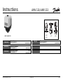
Danfoss AMV 110, AMV 113 Instrukcja obsługi
- Typ
- Instrukcja obsługi

Instructions
6 000 005 500 DEBC 08 / 01 VI.AA.W1.52
AMV 110, AMV 113
1 (19)
AMV 110, AMV 113
ENGLISH
DEUTSCH
Page 2
www.danfoss.com
Seite 2
www.danfoss.dk
Elektrischer Stellantrieb
AMV 110, AMV 113
Electrical Actuator
AMV 110, AMV 113
FRANCAIS
POLSKI
Servomoteur électrique
AMV 110, AMV 113
Page 2
www.danfoss.dk
Strona 2
www.danfoss.pl
Si³ownik elektryczny
AMV 110, AMV 113
VIM 2
VIU 2
VIS 2
AIQM

2
AMV 110, AMV 113
FRANCAIS POLSKI
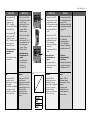
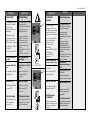
Spis treci
Warunki
bezpieczeñstwa 3
Zakres zastosowañ 3
Funkcja bezpieczeñstwa
sprê¿yny
powrotnej i kierunek
dzia³ania 4
Typy zaworów do AMV41.4
Monta¿ 5
Dopuszczalne pozycje
monta¿u 5
Monta¿ zaworu 6
Monta¿ si³ownika i
zaworu 7
Izolacja 9
Wymiary / Wagi 9
Pod³¹czenie elektryczne10
Schemat pod³¹czeñ
elektrycznych 11
Nastawy mechaniczne
si³ownika 12
Regulacja prze³¹czników
krañcowych 14
Nastawy potencjometru16
Demonta¿ zaworu i
si³ownika 18
Próba cinieniowa 19
DEUTSCH
Inhalt
Sicherheitshinweise 3
Bestimmungsgemäße
Verwendung 3
Sicherheitsfunktion und
Wirkrichtung 4
Ventiltypen für AMV... 4
Montage 5
- Zulässige
Einbaulagen 5
- Einbau Ventil 6
- Montage Stellantrieb
und Ventil 7
- Isolierung 9
- Abmessungen,
Gewichte 9
Elektrischer Anschluss 10
Elektrischer
Anschlussplan 11
Mechanische
Hubeinstellung 12
Einstellung der
Endschalter 14
Einstellung
Potentiometer 16
Demontage 18
Drückprüfung 19
ENGLISH
Contents
Safety notes 3
Defifintion of application 3
Safety Return Function and
Effective Direction. 4
Valve Types for
AMV 11. 4
Mounting 5
Permissible Installation
Positions 5
- Valve Installation 6
- Actuator and Valve
Installation 7
- Insultation 9
- Dimensions, Weights 9
Electrical Connection 10
Electrical Connection
Diagram 11
Mechanical Stroke
Setting 12
- Adjusting the End
Switches 14
Potentiometer Settings 16
Dismounting of Valve and
Actuator 18
Pressure test 19
FRANCAIS
Sommaire
Consignes de sécurité 3
Conditions d’utilisation 3
Fonction de secours et
sens de fonctionnement 4
Types de vannes
pour AMV.... 4
Montage 5
- Orientations de montage
autorisées 5
- Montage vanne 6
- Montage moteur
et vanne 7
- Isolation 9
- Dimensions / poids 9
Branchement électrique10
Schéma de branchement
électrique 11
Réglage mécanique de la
course 12
Réglage des contacts fins
de course 14
Réglage du
potentiomètre 16
Démontage 18
Contrôle de pression 19

3
AMV 110, AMV 113
DEUTSCH
Sicherheitshinweise
Um Verletzungen an Perso-
nen und Schäden am Gerät
zu vermeiden, diese Anlei-
tung unbedingt beachten.
Montage, Inbetriebnahme
und Wartungsarbeiten
dürfen nur von sach-
kundigen und autorisierten
Personen durchgeführt
werden.
Anlage vor Montage,
Demontage unbedingt
drucklos machen.
Die Vorgaben des Anlagen-
herstellers und Anlagen-
betreibers sind zu
beachten.
Bestimmungsgemäße
Verwendung
Der elektrische Stellantrieb
wird in Verbindung mit
folgenden Ventilen
eingesetzt: VIM 2, VIS 2,
VIU 2, AIQM
Einsatzgebiete sind
Temperaturregelung von
Wasser, Wasser-
Glykolgemischen und
Dampf für Heizungs-,
Fernheizungs- und
Kühlungsanlagen.
.
ENGLISH
Safety Notes
To avoid injury of persons
and damage to the
device, it is absolutely
necessary to carefully
read and observe these
Instructions.
Necessary assembly,
start-up, and maintenance
work may be performed
only by qualified and
authorized personnel.
Prior to assembly and
disassembly,
depressurize system!
Please comply with the
instructions of the system
manufacturer or system
operator.
Definition of
Application
The electrical actuator is
used in connection with
the following valves:
VIM 2, VIS 2, VIU 2, AIQM.
Fields of application are
the temperature control of
water, water-glycol
mixtures and steam for
heating, district heating
and cooling systems.
.
FRANCAIS
FRANCAIS
Consignes de
sécurité
Pour éviter les risques de
blessure pour les
personnes et les
dommages sur l’appareil,
lire attentivement cette
notice.
Le montage, la mise en
route et les travaux
d’entretien doivent être
effectués par du personnel
qualifié et autorisé.
Mettre impérativement
l’installation hors pression
avant tout montage ou
démontage.
Respecter les consignes
du fabricant de l’installation
et de l’exploitant de celle-
ci.
Conditions
d’utilisation
Le servomoteur électrique
est utilisé en combinaison
avec les vannes suivantes :
VIM 2, VIS 2, VIU 2, AIQM
Domaines d’application :
régulation de la
température de l’eau, de
l’eau glycolée et de la
vapeur pour chauffage,
chauffage urbain et
installations de
réfrigération.
POLSKI
Warunki
bezpieczeñstwa
W celu unikniêcia ryzyka
zranienia osób i
uszkodzenia urz¹dzeñ
nale¿y bezwzglêdnie i
wnikliwie zapoznaæ siê z
niniejsz¹ instrukcj¹.
Niezbêdny monta¿,
uruchomienie oraz
obs³uga mog¹ byæ
dokonywane wy³¹cznie
przez wykwalifikowany i
autoryzowany personel.
Nale¿y bezwzglêdnie
zrzuciæ cinienie z uk³adu
przed monta¿em i
demonta¿em.
Prosimy stosowaæ siê do
instrukcji producenta i/lub
operatora uk³adu.
Zakres zastosowañ
Si³ownik elektryczny
stosowany jest w
po³¹czeniu z
nastêpuj¹cymi zaworami:
VIM 2, VIS 2, VIU 2, AIQM
Znajduj¹ zastosowanie w
regulacji temperatury
wody, roztworu woda-glikol
i pary wodnej w uk³adach
grzewczych, instalacjach
sieci cieplnych i
ch³odzenia.

4
AMV 110, AMV 113
DEUTSCH
Sicherheitsfunktion
und Wirkrichtung
siehe Tabelle T1
Ventiltypen für
AMV 110.
Der elektrische Stellantrieb
AMV 110. kann auf
folgende Ventile montiert
werden, siehe Tabelle T2
ENGLISH
Safety Function and
Effective Direction
see table T1
Valve Types for
AMV 110.
The electrical actuator
AMV 110. can be mounted
on the following valves,
see table T2.
FRANCAIS FRANCAIS
Fonction de secours
et sens de
fonctionnement
Voir tableau 1
Types de vannes
pour AMV 110.
Le moteur électrique AMV
110. peut être monté sur
les vannes suivantes, voir
tableau 2
POLSKI
Funkcja
bezpieczeñstwa
sprê¿yny powrotnej i
kierunek dzia³ania
patrz Tabela T1
Typy zaworów do
AMV 110.
Si³ownik elektryczny typu
AMV 110. mo¿e
wspó³pracowaæ z
zaworami regulacyjnymi,
zgodnie z Tabel¹ T2.
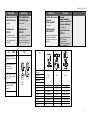
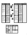
T2
Valve type
Ventiltyp VIM 2 VIS 2 AIQM
Type de vanne VIU 2
Typ zaworu
DN 15 - 50 15 - 25 15 - 50
PN 25
Medium Hot water Steam Hot water
Medium Heisswasser Dampf Heisswasser
Fluide Eau chaude Vapeur Eau chaude
Czynnik Gor¹ca woda Para wodna Gor¹ca woda
t
max Medium
°C 150 200 150
VIU 2
VIM 2
VIS 2
AIQM
➀
T1 AME 110 113
-+
Safety return function
and effective direction of
stem
➀
Sicherheitsfunktion und
Wirkrichtung der
Antriebsstange
➀
Fonction de secours et
sens de fonctionnement
de la tige
➀
Funkcja bezpieczeñstwa
i kierunek dzia³ania
trzpienia
➀

5
AMV 110, AMV 113
DEUTSCH
Montage
Zulässige Einbaulagen
Ventile VIM 2, AIQM
Die Einbaulage ist
beliebig. In waagrechten
Rohrleitungen ist der
Antrieb vorzugsweise
nach oben stehend
einzubauen.
Ventile VIS 2
Medium Dampf
ENGLISH
Mounting
Permissible Installation
Positions
Valves VIM 2, AIQM
The installation position is
optional. In horizontal
pipelines, the actuator
should preferably installed
in an upward standing
position.
Valves VIS 2
Medium steam
FRANCAIS
FRANCAIS
Montage
Orientations de montage
autorisées
Vannes VIM2, AIQM
L’orientation de montage
est au choix. Dans des
tuyauteries horizontales,
le moteur est à monter de
préférence vers le haut.
Vannes VIS2
Fluide vapeur
POLSKI
Monta¿
Dopuszczalne pozycje
monta¿u
Zawory VIM 2, AIQM
Pozycja monta¿u jest
dowolna. W instalacjach
poziomych si³ownik zaleca
siê montowaæ skierowany
do góry.
Zawory VIS 2
Czynnik para wodna
VIM 2, VIU 2
AIQM
VIS 2

6
AMV 110, AMV 113
DEUTSCH
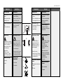
Einbau Ventil
1.Schmutzfänger vor dem
Ventil einbauen
2.Anlage vor dem Einbau
des Ventils spülen
3.Durchflussrichtung ➀ auf
dem Typenschild
beachten
Ausführung mit Flansch
Flansche
➁ in der Rohr-
leitung müssen parallel,
Dichtflächen sauber und
ohne Beschädigung sein.
- Ventil einbauen
- Schrauben über Kreuz in
3 Stufen bis zum max.
Drehmoment anziehen
Ausführung mit
Schweißénden
➂ nur heften
➃ schweißen
➀
➁
➃
FRANCAIS
➂
Flanges Design
Flanges ➁ in the pipeline
system must be in parallel
direction, the sealing
surfaces must be clean
and undamaged.
- Install valve
- Tighten screws
crosswise in 3 steps
up to the max. torque.
Welded Ends Design
➂ pin only
➃ weld
FRANCAIS
Montage vanne
1. Monter le filtre devant la
vanne
2. Rincer l’installation avant
le montage de la vanne
3. Respecter le sens
d’écoulement
➀ indiqué
sur la plaque
signalétique
Exécution avec brides
Les brides ➁ dans la
tuyauterie doivent être
parallèles, les surfaces
d’étanchéité propres et
sans dommages.
- Monter la vanne
- Serrer les vis en 3 étapes
en croix, jusqu’au couple
de rotation max.
Exécution avec embouts à
souder
➂ Uniquement souder par
points
➃ Souder
POLSKI
Monta¿ zaworu
1. Zamontowaæ filtr przed
zaworem.
2. Przed zamontowaniem
zaworu przep³ukaæ
instalacjê.
3. Zwróciæ uwagê na
wskanik kierunku
przep³ywu na korpusie
zaworu
➀ .
U³o¿enie ko³nierzy
Ko³nierze ➁ na ruroci¹gu
musz¹ byæ wzajemnie
równoleg³e, a
powierzchnie pod
uszczelki czyste i bez
uszkodzeñ.
- Zamontowaæ zawór.
- Dokrêcaæ przeciwleg³e
nakrêtki w 3 krokach do
osi¹gniêcia
maksymalnego
momentu.
U³o¿enie koñcówek do
spawania
➂ tylko koñcówki
➃ spawaæ
ENGLISH
Valve Installation
1.Install strainer in front of
valve.
2.Rinse system before
installing valve.
3.Observe flow direction
➀
on the valve body.

7
AMV 110, AMV 113
DEUTSCH
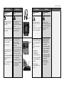
Montage Stellantrieb und
Ventil
Der Stellantrieb darf nur
mit eingefahrener
Schubstange ➀ montiert
werden.
Hubanzeige ➁ muss in
Position ➁ stehen
Bei Auslieferung ist die
Schubstange mittels
eingeschraubter
Montagechraube
➃
eingefahren.
Ist das nicht der Fall, dann :
1.elektrischen Anschluss
durchführen, siehe
nächsten Abschnitt
2. Taster
➂ drücken und
Schubstange ➀
vollständig einfahren
3.Montageschraube
➃ bis
zum Anschlag
einschrauben
ENGLISH
Actuator and Valve
Installation
The actuator must only be
mounted with the stem
retracted ➀.
Stroke indicator ➁ must be
in position ➁.
On delivery the stem is
retracted with a screwed-in
mounting screw
➃.
If this is not the case,
then:
1.carry out the electrical
connection, see next
section,
2. press pushbutton ➃ and
completely retract the
stem ➀.
3.Screw in mounting screw
➃ up to its stop
➂
➀
➁
➃
FRANCAIS
Montage moteur et
vanne
Uniquement monter le
moteur avec la tige ➀
rétractée
L’indication de course
➁
doit être en position ➁
Lors de la livraison, la tige
est rétractée à l’aide de la
vis de montage
➃ qui est
vissée
Si cela n’est pas les cas,
alors :
1. Procéder au
branchement
électrique, voir
prochain paragraphe
2. Presser la touche ➂ et
rétracter totalement la
tige ➀
3. Visser la vis de
montage
➃ jusqu’en
butée
POLSKI
Monta¿ si³ownika i
zaworu
Si³ownik mo¿e byæ
zamontowany gdy trzpieñ
jest cofniêty ➀. Wskanik
poziomu musi byæ w
pozycji ➁.
W przypadku dostawy
trzpieñ jest cofniêty i
zaplombowany rub¹
monta¿ow¹
➃.
W przeciwnym wypadku:
1. wykonaæ po³¹czenie
elektryczne, patrz
nastêpny rozdzia³.
2. nacinij przycisk
➂ do
ca³kowitego cofniêcia
trzpienia ➀
3. wkrêciæ rubê
monta¿ow¹ a¿ do
zatrzymania

8
AMV 110, AMV 113
DEUTSCH
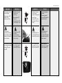
3.Stellantrieb am Ventil
ansetzen und
ausrichten
4.Überwurfmutter
➀
anziehen
Anzugsmoment 35 Nm,
Schlüsselweite 36 mm
5.
Montageschraube
➁
unbedingt
herausschrauben,
sonst ist der Stellantrieb
außer Funktion
6. Bei hängendem Einbau
des Stellantriebs
➂
Aufkleber ➃ entfernen
➂
➁
3 mm
➃
ENGLISH
3.Place actuator on the
valve and align.
4.Tighten union nut
➀
torque 35 Nm,
wrench size 36 mm
5.
It is absolutely
necessary to unscrew
the mounting screw
➁,
otherwise, the actuator
is out of function.
6. If the actuator is installed
in a downward hanging
position
➂, remove
label ➃.
➀
FRANCAIS FRANCAIS
3. Positionner le moteur
sur la vanne et
procéder à l’alignement
4. Serrer l’écrou
prisonnier
➀, facteur
de serrage 35 Nm, clé
36 mm
5.
Dévisser
impérativement la vis
de montage
➁, sinon le
moteur est hors fonction
6. Lors d’un montage du
moteur
➂ vers le bas,
retirer l’autocollant ➃
POLSKI
3. Umieciæ si³ownik na
zaworze
4. Dokrêciæ nakrêtkê
³¹cz¹c¹
➀. Moment 35
Nm, klucz 36 mm
5.
Nale¿y koniecznie
wykrêciæ rubê
monta¿ow¹
➁ w innym
przypadku si³ownik nie
bêdzie dzia³a³.
6. Kiedy napêd jest
skierowany do do³u
➂
usun¹æ nalepkê ➃

9
AMV 110, AMV 113
DEUTSCH
Isolierung
➀ zulässig
➁ unzulässig
Abmessungen, Gewichte
Flansche Anschlussmaße
nach DIN 2501, Dichtleiste
Form C
ENGLISH
Insulation
➀ acceptable
➁ intolerable
Dimensions, Weights
Flanges: connection
dimensions acc. to
DIN 2501, seal form C
235
14 5
AMV(E) 110, 113
➀
➁
FRANCAIS
FRANCAIS
Isolation
➀ Autorisé
➁ Non autorisé
Dimensions, poids
Dimensions raccordement
à brides selon DIN 2501,
étanchéité forme C
POLSKI
Izolacja
➀ do przyjêcia
➁ nie do przyjêcia
Rozmiar, Waga
Ko³nierze wymiary
po³¹czeñ zgodne z DIN
2501, uszczelka typu C.

10
AMV 110, AMV 113
DEUTSCH
Elektrischer
Anschluss
Gefahr durch
Stromschlag!
Bei unsachgemäßer
Handhabung besteht
Lebens- oder
Verletzungsgefahr.
Vor dem Anschluss der
Leitungen unbedingt
Spannungsversorgung
abschalten.
Durchführung des
elektrischen Anschlusses
nur durch Elektrofachkraft.
Vorgehensweise
1.Hutmutter
➀
abschrauben und Haube
➁ abnehmen
2. Leitungen nach dem
Anschlussplan
anschließen,
siehe nächste Seite
3. Vor Montage der Haube,
Einstellungen am
Stellantrieb durchführen,
siehe nächsten Abschnitt
➀
➁
ENGLISH
Electrical
Connection
HIGH VOLTAGE !
Danger of injury and life
in case of improper
handling.
Switch off power supply
prior to connecting lines.
The electrical connection
must only be performed by
an expert electrician.
Procedure
1.Unscrew cap nut
➀ and
remove cover ➁.
2.Connect lines in
accordance with
connection diagram,
see next page.
3. Prior to remounting the
cover, carry out settings
at the actuator,
see next section.
FRANCAIS
FRANCAIS
Branchement
électrique
Danger d’électrocution
Lors d’une manipulation
non appropriée, danger
de mort ou risques de
blessures
Avant le branchement des
câbles, impérativement
couper l’alimentation.
Le branchement doit être
effectué uniquement par
du personnel qualifié.
Procédure :
1. Dévisser l’écrou du
capot
➀ et retirer le
capot ➁
2. Raccorder les câbles
selon le schéma de
branchement, voir page
suivante
3. Avant de remettre le
capot, effectuer les
réglages sur le moteur,
voir paragraphe suivant
POLSKI
Pod³¹czenie
elektryczne
WYSOKIE NAPIÊCIE !
Ryzyko obra¿eñ i
zagro¿enie ¿ycia w
przypadku
nieprawid³owej obs³ugi.
Przed wykonaniem
pod³¹czeñ elektrycznych
nale¿y bezwzglêdnie
wy³¹czyæ zasilanie.
Pod³¹czenia elektryczne
mog¹ byæ wykonane
wy³¹cznie przez
uprawnionego elektryka.
Tryb postêpowania
1. Odkrêciæ rubê
➀ i
usun¹æ obudowê ➁.
2. Pod³¹czyæ przewody
zgodnie ze schematem
pod³¹czeñ elektrycznych
- patrz nastêpna strona.
4. Przed za³o¿eniem
obudowy wykonaæ
wszystkie nastawy
si³ownika - patrz
nastêpny rozdzia³.

11
AMV 110, AMV 113
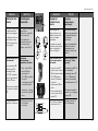
1
11 12 13 14 15 16 20 21 22
PE
L R
1 2
1 2
44
S1 S2
End switches
CV
C
M
2
34
789
10
N
L
Pot
5 k
W
max. 1W
1 2 3
17 18
manual
DEUTSCH
Elektrischer
Anschlussplan
➀ Anschluss für:
STB - Sicherheits-
temperaturbegrenzer
STW - Sicherheits-
temperaturwächter
SDB- Sicherheits-
druckbegrenzer
bei Anschluss unbedingt
Brücke entfernen
nur Typen AMV 110 mit
Sicherheitsfunktion
ENGLISH
Electrical Connection
Diagram
➀ Connection for:
STB - Safety Temperature
Limiter
STW - Safety Temperature
Monitor
SDB - Safety Pressure
Limiter
Prior to connection, it is
absolutely necessary to
remove the jumper
only types AMV 110
with safety return function.
➀
AMV 113
FRANCAIS
FRANCAIS
Schéma de branchement
électrique
➀ Branchement pour :
STB – Limiteur de
température de sécurité
STW – Contrôleur de
température de sécurité
SDB – Limiteur de
pression de sécurité
Lors du branchement,
impérativement retirer le
pont
Uniquement types AMV
110 avec fonction de
secours
POLSKI
Schemat pod³¹czeñ
elektrycznych
➀ Zaciski do:
STB Ogranicznik
temperatury
bezpieczeñstwa
STW Stra¿nik temperatury
bezpieczeñstwa
SDB Ogranicznik
cinienia bezpieczeñstwa
Przed po³¹czeniem nale¿y
koniecznie usun¹æ
mostek. dot. wy³¹cznie
typów AMV 110 z funkcj¹
sprê¿yny powrotnej.
230 VAC
Power Spannungs- Alimentation Napiêcie
supply versorgung zasilania
3-position Dreipunkt- Régulateur 3 Regulacja
step Schritt-Regler points sygna³em 3
controller -
punktowym
Open valve Ventilöffnen Ouvrir la vanne Prze³¹czniki
(Close VIU2) (VIU2) schliessen) (fermer VIU2) krañcowe
Close valve Ventil schliessen Fermer la vanne Zawór zamkniêty
(Open VIU2) (VIU2 Öffnen) (ouvrir VIU2) (VFU 2 otwarty)
Valve open Ventil Auf Vanne ouverte Zawór otwarty
(VIU2 closed) (VIU2 zu) (VIU2 fermée) (VFU 2 zamkniêty)
End switches Endschalter Contacts fin Prze³¹czniki
de course krañcowe
Valve closed Ventil zu Vanne fermée Zawór zamkniêty
(VIU2 Open) (VIU2 auf) (VIU2 ouverte) (VIU2 otwarty)
Pot Potentiometer Potentiometer Potencjometr
Valve open Ventil Auf Vanne ouverte Zawór otwarty
(VIU2 closed) (VIU2 zu) (VIU2 fermée) (VIU 2 zamkniêty)
Stroke Hub Course Skok
Valve closed Ventil zu Vanne fermée Zawór zamkniêty
(VIU2 open) (VIU2 auf) (VIU2 ouverte) (VIU2 otwarty)

12
AMV 110, AMV 113
DEUTSCH
Mechanische
Hubeinstellung
Bei Ausführung mit
Potentiometer, zuerst die
Einstellung des
Potentiometers
durchführen,
siehe Seite 16
Der Hub des elektrischen
Stellantriebs muss dem
Ventilhub angepasst
werden.
1. Falls noch nicht
durchgeführt, die
Montageschraube
➀
herausschrauben
2.Taster
➁ drücken bis
das Ventil ➂ ganz
geschlossen ist
(VIU 2 ➃ ganz geöffnet
ist) und die Lauf-
richtungsanzeige ➄
zum Stillstand kommt
Hubanzeige
beachten, sie muss bis
Position
➅ fahren
➁
➀
3 mm
➂
➃ VIU 2
ENGLISH
Mechanical Stroke
Setting
For designs with
potentiometer, first carry
out the settings for the pot,
see page 16.
The stroke of the electrical
actuator must be adjusted
to the valve stroke.
1. If not yet done, unscrew
the mounting screw
➀.
2.Press pushbutton
➁
until the valve ➂ is
completely closed
(VIU 2 ➃ completely
open) and the direction
indicator ➄ stops.
Observe stroke indicator,
it must move to position
➅.
➅
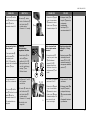
➄
VIM2
VIS2
AIQM
FRANCAIS
FRANCAIS
Réglage mécanique
de la course
Pour une exécution avec
potentiomètre, procéder
d’abord au réglage du
potentiomètre, voir page 16
La course du moteur doit
être adaptée à la course de
la vanne
1. Si cela n’est pas fait,
dévisser la vis de
montage
➀
2. Presser la touche ➁
jusqu’à ce que la vanne
➂ soit totalement fermée
(VFU2 ➃ totalement
ouverte),
et l’indicateur de sens de
fonctionnement
➄ soit
arrêté
Observer l’indication de
course, elle doit aller
jusqu’en position
➅
POLSKI
Nastawy
mechaniczne
si³ownika
Dla wersji z
potencjometrem, najpierw
przeprowadziæ nastawy
dla potencjometru
Patrz strona 16.
Skok si³ownika
elektrycznego musi byæ
przystosowany do skoku
zaworu.
1. Je¿eli nie jest to
jeszcze zrobione,
odkrêciæ rubê
monta¿ow¹
➀.
2. Wcisn¹æ przycisk
➁ a¿
do ca³kowitego
zamkniêcia zaworu ➂
(VFU 2 ➃ ca³kowitego
otwarcia) i do
zatrzymania wskanika
poziomu ➄
Obserwowaæ wskanik
poziomu, musi
osi¹gn¹æ pozycjê
➅.

13
AMV 110, AMV 113
DEUTSCH
3.Hubeinstellschraube ➆
bis zum Anschlag
eindrehen
4. Ventilhub aus Tabelle T1
entnehmen
5.Hubeinstellschraube ➇
pro mm Ventilhub um
eine Umdrehung
herausdrehen
➻ Die Hubeinstellung ist
abgeschlossen
Hinweis
Der Stellantrieb ist mit
einem Grenzmoment-
synchronmotor ausgeführt.
Der Motor schaltet in den
Endlagen nicht ab, er läuft
lastfrei weiter.
T1
➇
ENGLISH
3.Screw in stroke setting
screw
➆ up to its stop.
4. Take valve stroke from
table T1.
5.Unscrew stroke setting
screw
➇ by one turn
per mm valve stroke.
➻The stroke setting is
completed.
Note
The actuator is equipped
with a maximum torque
synchronous motor.
The motor is not switched
off at the end positions but
continues to run in off-load
operation.
➆
FRANCAIS
FRANCAIS
3. Serrer la vis de réglage
de course
➆ jusqu’en
butée
4. Relever la course de la
vanne dans le tableau
T1
5. Dévisser la vis de
réglage de course
➇
d’un tour par mm de
course de vanne
➻ Le réglage de la course
est terminé
Indication
Le moteur est équipé d’un
moteur synchrone. Dans
les positions fins de
course, le moteur ne
coupe pas, il continu sans
charge.
POLSKI
3. Dokrêciæ rubê nastawy
skoku
➆, a¿ do jej
zatrzymania.
4. Odczytaæ skok zaworu z
poni¿szej tabeli T1
5. Odkrêciæ rubê nastawy
skoku
➇ jeden obrót
na 1 mm skoku zaworu.
➻ Nastawa skoku zosta³a
zakoñczona.
Uwaga
Si³ownik jest wyposa¿ony
w synchroniczny silnik
maksymalnego momentu.
Silnik nie jest wy³¹czany
po osi¹gniêciu pozycji
krañcowych, ale pracuje
w stanie ja³owym.
DN 15 20 25 32 40 50
Valve stroke VIM 2
AIQM 8 10 15
Ventilhub mm
Course vanne VIS 2 5 -
Skok Zaworu VIU 2 7

14
AMV 110, AMV 113
DEUTSCH
Einstellung der
Endschalter
Nur spezielle Stellantriebs-
typen sind mit
Endschaltern ausgeführt,
siehe Typenschild.
Die Einstellung der
Endschalter muss nach
der Hubeinstellung
erfolgen, siehe Seite 12
Endschalter
“Antriebsstange
ausgefahren” einstellen
1. Taster drücken ➁ bis
das Ventil ➂ ganz
geschlossen ist
(VIU 2 ➃ ganz geöffnet
ist) und die
Laufrichtungsanzeige ➄
zum Stillstand kommt
Hubanzeige beachten,
sie muss bis Position
➅
fahren
2. An Klemmen 14 und 16
ein Ohmmeter
anschließen
➁
➂
➃ VIU 2
➅
➄
11 12 13 14 15 16
1 2
1 2
44
S1 S2
End switches
Ω
ENGLISH
Adjusting the End
Switches
Only special actuator types
are equipped with end
switches, see rating plate.
The adjustment of the end
switches must be done
after the stroke has been
set, see page 12.
Adjusting the End Switch
“Stem extended”
1. Press pushbutton ➁
until the valve ➂ is
completely closed
(VIU 2 ➃ completely
open) and the direction
indicator ➄ stops.
Observe stroke indicator,
it must move to position
➅.
2. Connect terminals 14
and 16 to an ohmmeter.
VIM2
VIS2
AIQM
FRANCAIS
Réglage des
contacts fíns de
course
Seuls des types de
moteurs spéciaux sont
équipés de contacts fins
course, voir plaque
signalétique
Le réglage des contacts
fins de course doit se faire
après le réglage de la
course, voir page 12
Régler le contact fin de
course «tige du moteur
descendue»
1. Presser la touche
➁
jusqu’à ce que la vanne
➂ soit totalement fermée
(VFU2 ➃ totalement
ouverte) et l’indicateur
de sens de
fonctionnement ➄ soit
arrêté
Observer l’indication de
course, elle doit aller en
position
➅
2. Raccorder un ohmmètre
aux bornes 14 et 16
POLSKI
Regulacja
prze³¹czników
krañcowych.
Tylko si³owniki w wersji
specjalnej s¹ wyposa¿one
w prze³¹czniki krañcowe,
patrz tabliczka
znamionowa.
Regulacja prze³¹czników
krañcowych mo¿e byæ
przeprowadzona po
nastawieniu skoku, patrz
strona 12.
Regulacja prze³¹czników
krañcowych Trzpieñ
wysuniêty
1. Nacisn¹æ przycisk
➁ a¿
do ca³kowitego
zamkniêcia zaworu ➂
(VFU 2 ➃ ca³kowicie
otwarty) i zatrzymania
wskanika poziomu ➄.
Obserwowaæ wskanik
poziomu, musi osi¹gn¹æ
pozycjê
➅
2. Pod³¹czyæ zaciski 14 i
16 do omomierza.

15
AMV 110, AMV 113
DEUTSCH
4.Schraube ➀ drehen,
bis der Schaltnocken ➁
den Endschalter ➂
schaltet und das
Ohmmeter 0 Ω anzeigt
Endschalter
“Antriebsstange
eingefahren” einstellen
1.Taster drücken
➃ bis
das Ventil ➄ ganz
geöffnet ist ( VIU 2
➅
ganz geschlossen ist)
und die Laufrichtungs-
anzeige
➆ zum
Stillstand kommt
2. An Klemmen 11 und 12
ein Ohmmeter
anschließen
3.Schraube
➇ drehen, bis
der Schaltnocken ➈
den Endschalter ➉
schaltet und das
Ohmmeter 0 Ω anzeigt
➻Endschalter sind
eingestellt
➆
➃
ENGLISH
4.Turn screw ➀ until the
cam ➁ switches the end
switch ➂ and the
ohmmeter shows 0 Ω.
Adjusting the End Switch
“Stem retracted”
1. Press pushbutton ➃
until the valve ➄ is
completely open
(VIU 2 ➅ completely
closed) and the direction
indicator ➆ stops.
2. Connect terminals 11
and 12 to an ohmmeter.
3.Turn screw ➇ until the
cam ➈ switches the end
switch ➉ and the
ohmmeter shows 0 Ω.
➻The end switches are
adjusted.
➄ VFG..,
➅ VFU 2
FRANCAIS
3. Tourner la vis ➀ jusqu’à
ce que le commutateur
➁ commute le contact
fin de course ➂ et que
l’ohmmètre indique 0 Ω
Régler le contact fin de
course «tige du moteur
rétractée»
1. Presser la touche ➃
jusqu’à ce que la vanne
➄ soit totalement
ouverte (VFU2 ➅
totalement fermée) et
l’indicateur de sens de
fonctionnement
➆ soit
arrêté
2. Raccorder un ohmmètre
aux bornes 11 et 12
3. Tourner la vis ➇ jusqu’à
ce que le commutateur
➈ commute le contact
fin de course ➉ et que
l’ohmmètre indique 0 Ω
➻Les contacts fins de
course sont réglés
POLSKI
4. Przekrêcaæ rubê ➀ a¿
krzywka ➁ spowoduje
prze³¹czenie
prze³¹czników
krañcowych ➂, a
omomierz wska¿e 0 Ω.
Regulacja prze³¹czników
krañcowych Cofniêty
trzpieñ
1. Nacisn¹æ przycisk
➃ do
ca³kowitego otwarcia
zaworu ➄ (VFU 2 ➅
ca³kowicie zamkniêty) i
zatrzymania wskanika
poziomu
➆ .
2. Po³¹cz zacisk 11 i 12 do
omomierza.
3. Przekrêcaæ rubê
➇ a¿
krzywka ➈ roz³¹czy
prze³¹cznik krañcowy
➉, a omomierz wska¿e
0 Ω
➻ Prze³¹czniki krañcowe
s¹ nastawione.
➀
Ω
➈
➇
➉

16
AMV 110, AMV 113
DEUTSCH
Einstellung
Potentiometer
Nur spezielle Stellantriebs-
typen sind mit dem
Potentiometer ausgeführt,
siehe Typenschild.
Nach jeder Montage
Stellantrieb und Ventil und
nach Entfernen der
Montageschraube
folgendes durchführen:
Nullpunkt justieren
1.Taster drücken
➀ bis
das Ventil ➁ ganz
geschlossen ist
(VIU 2 ➂ ganz geöffnet
ist) und die
Laufrichtungsanzeige
➃ zum Stillstand kommt
Hubanzeige
beachten, sie muss bis
Position ➄ fahren
2.Hubeinstellschraube ➅
2 Umdrehungen aus
dem Muttergewinde
herausdrehen
➀
➁
➂ VFU 2
➄
➃
➅
ENGLISH
Potentiometer
Settings
Only special actuator types
are equipped with
potentiometers,
see rating plate.
After having mounted a
valve and an actuator and
after having removed the
mounting screw, carry out
the following steps:
Adjust zero point
1. Press pushbutton
➀
until the valve ➁ is
completely closed
(VIU 2 ➂ completely
open) and the direction
indicator ➃ stops.
Observe stroke indicator,
it must move to position
➄.
2.Unscrew stroke setting
screw
➅ by 2 turns out
of the female thread.
VIM2
VIS2
AIQM
FRANCAIS
Réglage du
potentiomètre
Seuls des types de
moteurs spéciaux sont
équipés d’un
potentiomètre, voir plaque
signalétique
Après chaque montage du
moteur et de la vanne et
après avoir retirer la vis de
montage, procéder comme
suit
Ajustement du point zéro
1. Presser la touche
➀
jusqu’à ce que la vanne
➁ soit totalement
fermée (VFU2 ➂
totalement ouverte) et
l’indicateur de sens de
fonctionnement
➃ soit
arrêté
Observer l’indication de
course, elle doit aller en
position
➄
2. Dévisser la vis de
réglage de course
➅ de
2 tours
POLSKI
Nastawy
potencjometra
Tylko si³owniki wersji
specjalnej s¹ wyposa¿one
w potencjometry, patrz
tabliczka znamionowa.
Po monta¿u zaworu i
si³ownika oraz usuniêciu
ruby monta¿owej
przeprowadziæ
nastêpuj¹ce kroki:
Regulacja punktu zero.
1. Nacisn¹æ przycisk
➀ a¿
do ca³kowitego
zamkniêcia (VFU 2 ➂
ca³kowite otwarcie) oraz
zatrzymania wskanika
poziomu
➃.
Obserwowaæ wskanik
poziomu musi osi¹gn¹æ
pozycjê
➄.
2. Odkrêciæ rubê nastawy
skoku
➅ dwa obroty w
gwincie wewnêtrznym.

17
AMV 110, AMV 113
DEUTSCH
3.Taster drücken ➀ bis
das Ventil ganz geöffnet
ist (VIU 2 ganz
geschlossen ist) und
die Laufrichtungs-
anzeige ➁ zum
Stillstand kommt
4.Taster
drücken ➂ bis
das Ventil ganz
geschlossen ist (VIU 2
ganz geöffnet ist) und
die Laufrichtungs-
anzeige ➁ zum
Stillstand kommt
➻ der Nullpunkt des
Potentiometers ist
justiiert
5. Anschließend die
Hubeinstellung
durchführen,
siehe Seite 12
Hinweis
Der Bereich 0- 5000 Ω
entspricht dem
Maximalhub (20 mm) des
Stellantriebs. Nach der
Hubeinstellung muss der
Widerstandswert
entsprechend dem
Ventilhub gemessen
werden.
➀
➁
➂
0 20 mm
0
5000 Ω
ENGLISH
3.Press pushbutton ➀
until the valve is
completely open
(VIU 2 completely
closed) and the direction
indicator
➁ stops.
4.Press pushbutton
➂
until the valve ➁ is
completely closed
(VIU 2 completely open)
and the direction
indicator ➁ stops.
➻ The zero point of the
potentiometer is
adjusted
5. Then, adjust the stroke,
see page 12
Note
The range 0- 5000 Ω
corresponds to the
maximum stroke (20 mm)
of the actuator.
After the stroke is adjusted,
the resistance must be
measured in accordance
with the valve stroke.
FRANCAIS
3. Presser la touche ➀
jusqu’à ce que la vanne
soit totalement ouverte
(VIU2 totalement fermée)
et l’indicateur de sens de
fonctionnement
➁ soit
arrêté
4. Presser la touche
➂
jusqu’à ce que la vanne
soit totalement fermée
(VIU2 totalement
ouverte) et l’indicateur
de sens de
fonctionnement
➁ soit
arrêté
➻➻
➻➻
➻Le point zéro du
potentiomètre est
ajusté
5. Ensuite procéder au
réglage de la course ,
voir page 12
Indication
La plage 0-5000 Ω
correspond à la course
maximum (20 mm) du
moteur. Après le réglage de
la course, la valeur de
résistance doit être
mesurée en fonction de la
course de la vanne.
POLSKI
3. Nacisn¹æ przycisk ➀ a¿
do ca³kowitego otwarcia
zaworu (VIU 2
ca³kowitego zamkniêcia)
i zatrzymania wskanika
poziomu ➁.
4. Nacisn¹æ przycisk
➂ a¿
do ca³kowitego
zamkniêcia zaworu
(VIU 2 ca³kowitego
otwarcia) i zatrzymania
wskanika poziomu ➁.
➻➻
➻➻
➻ Punkt zero
potencjometra jest
nastawiony
4. Nastêpnie przeprowad
nastawy mechaniczne
si³ownika patrz str. 12
Uwaga
Zakres 0 5000 Ω
odpowiada skokowi
maksymalnemu (20mm)
si³ownika.
Po regulacji skoku
rezystancja musi byæ
mierzona zgodnie ze
skokiem zaworu.
Stroke
Hub
Course
Skok

18
AMV 110, AMV 113
POLSKI
Demonta¿
Zawory VIM 2, VIS 2, VIU
2, AIQM s¹ uszczelnione w
miejscu ³¹czenia
➀.
Si³ownik mo¿e byæ
demontowany gdy uk³ad
jest pod cinieniem
Przed demonta¿em
zaworu nale¿y koniecznie
zrzuciæ cinienie z uk³adu.
ENGLISH
Dismounting
The valves VIM 2, VIS 2,
VIU 2, AIQM are sealed at
the connection
➀. The
actuator may be
dismounted while the
system is pressurized.
Prior to dismounting the
valve, is is absolutely
necessary to depressurize
the system.
DEUTSCH
Demontage
Die Ventile VIM 2, VIS 2,
VIU 2, AIQM sind am
Anschluss
➀ abgedichtet.
Der Stellantrieb kann bei
unter Druck stehender
Anlage demontiert werden.
Vor Demontage des
Ventils die Anlage
unbedingt drucklos
machen.
➁
➀
FRANCAIS
FRANCAIS
Démontage
L’étanchéité des vannes
VIM2, VIS2, VIU2, AIQM se
trouve dans le
raccordement
➀
Le moteur peut être
démonté lorsque
l’installation est sous
pression.
Impérativement mettre
l’installation hors pression
avant le démontage de la
vanne

19
AMV 110, AMV 113
DEUTSCH
Druckprüfung
Bei Drücken größer 16 bar,
keinesfalls bei ge-
schlossenem Ventil prüfen.
Das Ventil kann sonst
beschädigt werden.
Bei dem Stellantrieb
AME(V) 113 mit Sicher-
heitsfunktion ist ohne
Netzversorgung die
Antriebsstange ausge-
fahren:
Ventile VIM2, VIS 2, AIQM
sind “ZU”
Ventile VIU 2 sind “AUF”
Vor Druckprüfungen
Ventil öffnen
Ventile VIM2, VIS 2, AIQM
öffnen:
Taster drücken
➀ und
Antriebsstange ➁
einfahren
Ventile VIU 2 öffnen
Taster drücken ➂ und
Antriebsstange ➃
ausfahren
Füllung der Anlage
Vorher sicherstellen, dass
das Ventil „Auf“ ist, siehe
oben „Druckprüfung“.
➀
➂
➁
➃
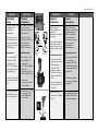
VIM 2, VIS 2 AIQM
FRANCAIS
ENGLISH
Pressure Test
For pressures larger than
16 bar, do NOT test with
the valve closed.
Otherwise, the valve can
be damaged.
Without power supply ,
the stem of the actuator
AME(V) 113 with safety
return function is extended:
Valves VIM2, VIS 2, AIQM
are “CLOSED”,
Valves VIU 2 are “OPEN”.
Prior to pressure tests,
open valve.
Open valves VIM2, VIS 2,
AIQM:
Press pushbutton
➀ and
retract stem ➁.
Open valves VIU 2:
Press pushbutton
➂ and
retract stem ➃.
Filling the System
First ensure that valve is
“OPEN”, see above
“Pressure Test”.
FRANCAIS
Contrôle de
pression
Avec des pressions
supérieures à 16 bar, ne
pas effectuer les contrôles
vanne fermée. Sinon la
vanne peut être détériorée.
Pour les moteurs AME(V)
113 avec fonction de
secours, la tige est
descendue sans
alimentation :
Vannes VIM2, VIS2, AIQM
sont «fermées»
Vannes VIU2 sont
«ouvertes»
Avant les contrôles de
pression, ouvrir la vanne
Ouvrir les vannes VIM2,
VIS2, AIQM :
Presser la touche
➀ et
rétracter la tige ➁
Ouvrir les vannes VIU2
Presser la touche ➂ et
descendre la tige ➃
Remplissage de
l’installation
D’abord s’assurer que la
vanne soit «ouverte», voir
ci-dessus «contrôle de
pression»
POLSKI
Próba cinieniowa
Nie podawaæ cinienia
wiêkszego ni¿ 16 bar gdy
zawór jest zamkniêty.
Nieprzestrzeganie
powy¿szego mo¿e
spowodowaæ uszkodzenie
zaworu.
Przy braku napiêcia
zasilaj¹cego, trzpieñ
si³ownika AME(V) 113 z
funkcj¹ bezpieczeñstwa
sprê¿yny powrotnej jest
wysuniêty:
Zawory VIM 2, VIS 2, AIQM
s¹ Zamkniête, zawory
VIU 2 s¹ Otwarte
Przed próbami
cinieniowymi otworzyæ
zawór.
Otwarcie zaworów VIM 2,
VIS 2, AIQM:
Naciskaæ przycisk ➀ co
powoduje cofanie trzpienia
Otwieranie zaworów VIU
2:
Naciskaæ przycisk ➂, co
powoduje wysuwanie
trzpienia ➃.
Nape³nianie uk³adu
Upewnij siê czy zawór jest
Otwarty patrz powy¿ej
Próba cinieniowa
-
 1
1
-
 2
2
-
 3
3
-
 4
4
-
 5
5
-
 6
6
-
 7
7
-
 8
8
-
 9
9
-
 10
10
-
 11
11
-
 12
12
-
 13
13
-
 14
14
-
 15
15
-
 16
16
-
 17
17
-
 18
18
-
 19
19


Danfoss AMV 110, AMV 113 Instrukcja obsługi
- Typ
- Instrukcja obsługi
w innych językach
Powiązane artykuły
-
Danfoss AMV 410, 413 Instrukcja obsługi
-
-
-
Danfoss AIQM Instrukcja obsługi
-
-
-
-
-
-