
Instructions
7369603-0 SIBC 04 / 04 VI.AA.X1.6U
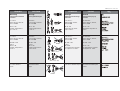
AME (-H) 610, 613, 633
1 (21)
ENGLISH
DEUTSCH
Page 2
www.danfoss.com
Elektrischer Stellantrieb
AME (-H) 610, 613, 633
Seite 2
www.danfoss.de
VFG 2
VFG 21
VFG 25
VFU 2 VFGS 2 AFQM
Page 2
www.danfoss.fr
FRANCAIS
POLSKI
Electrical Actuator
AMV (-H) 610, 613, 633
Servomoteur électrique
AMV (-H) 610, 613, 633
Si³ownik elektryczny
AME (-H) 610, 613, 633
Strona 2
www.danfoss.pl

2
AME (-H) 610, 613, 633
DEUTSCH
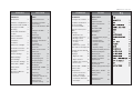
Inhalt
Sicherheitshinweise 3
Bestimmungsgemäße
Verwendung 3
Übersicht Stellantriebe AME
.. 4
Ventiltypen für AME ... 4
Montage 5
- Zulässige
Einbaulagen 5
- Einbau Ventil 6
- Montage Stellantrieb
und Ventil 7
- Isolierung 8
- Abmessungen,
Gewichte 8
Elektrischer Anschluss 9
Elektrischer
Anschlussplan 10
Einstellungen 11
- Ausgangssignal 11
- Eingangssignal 11
- Einstellung der
Endlagen 12
Ventile VFG.., AFQM 12
Ventile VFU 15
Bedienung 18
- Drehschalter-
stellungen, elektrische
Handverstellung 18
- Mechanische
Handverstellung 19
FRANCAIS
Sommaire
Consignes de sécurité 3
Conditions d’utilisation 3
Vue d’ensemble
servomoteurs AME .... 4
Types de vannes pour
AME.... 4
Montage 5
- Orientations de
montage autorisées 5
- Montage vanne 6
- Montage moteur
et vanne 7
- Isolation 8
- Dimensions / poids 8
Branchement électrique 10
Schéma de branchement
électrique 11
Réglages 12
- Signal de sortie 12
- Signal d’entrée 12
- Réglage des positions
fin de course 13
Vannes VFG..., AFQM 13
Vannes VFU 16
Manipulation 19
- Positions du bouton
rotatif, commande
manuelle électrique 19
- Commande manuelle
mécanique 20
POLSKI
Spis treci
Warunki
bezpieczeñstwa 3
Zakres zastosowañ 3
Przegl¹d
si³owników AME 4
Typy zaworów
do AME(-H) 4
Monta¿ 5
- Dopuszczalne pozycje
monta¿u 5
- Monta¿ zaworu 6
- Monta¿ si³ownika
i zaworu 7
- Izolacja 8
- Wymiary / Wagi 8
Pod³¹czenie elektryczne 10
Schemat pod³¹czeñ
elektrycznych 11
Nastawy si³ownika 12
Nastawy sygna³ów
wyjciowych 12
Nastawy sygna³ów
wejciowych 12
Nastawy pozycji krañcowych
13
Zawory VFG..., AFQM 13
Zawory VFU2 16
Dzia³anie 19
Regulacja rêczna -
mechaniczna 20
ENGLISH
Contents
Safety Notes 3
Definition of Application 3
Overview Actuators AME 4
Valve types for AME 4
Mounting 5
Permissible Installation
Position 5
Valve Installation 6
Actuator and Valve
installation 7
Insultation 8
Dimensions, Weights 8
Electrical Connection 10
Electrical Connection
Diagrams 11
Actuator Settings 12
Output Settings 12
Input Settings 12
Final Position Settings 13
Valves VFG...,AFQM 13
Valves VFU2 16
Operation 19
Mechanical Manual
Adjustments 20

3
AME (-H) 610, 613, 633
DEUTSCH
Sicherheitshinweise
Um Verletzungen an Perso-
nen und Schäden am Gerät
zu vermeiden, diese Anlei-
tung unbedingt beachten.
Montage, Inbetriebnahme
und Wartungsarbeiten
dürfen nur von sach-
kundigen und autorisierten
Personen durchgeführt
werden.
Anlage vor Montage,
Demontage unbedingt
drucklos machen.
Die Vorgaben des Anlagen-
herstellers und Anlagen-
betreibers sind zu
beachten.
Bestimmungsgemäße
Verwendung
Der elektrische Stellantrieb
wird in Verbindung mit
folgenden Ventilen
eingesetzt: VFG 2(21),
VFG 25, VFU 2, VFGS 2,
AFQM
Einsatzgebiete sind
Temperaturregelung von
Wasser, Wasser-
Glykolgemischen und
Dampf für Heizungs-,
Fernheizungs- und
Kühlungsanlagen.
FRANCAIS
Consignes de
sécurité
Pour éviter les risques de
blessure pour les
personnes et les
dommages sur l’appareil,
lire attentivement cette
notice.
Le montage, la mise en
route et les travaux
d’entretien doivent être
effectués par du personnel
qualifié et autorisé.
Mettre impérativement
l’installation hors pression
avant tout montage ou
démontage.
Respecter les consignes du
fabricant de l’installation et
de l’exploitant de celle-ci.
Conditions
d’utilisation
Le servomoteur électrique
est utilisé en combinaison
avec les vannes suivantes
VFG 2(21), VFG 25, VFU 2,
VFGS2, AFQM
Domaines d’application :
régulation de la
température de l’eau, de la
température de l’eau, de
l’eau glycolée et de la
vapeur pour chauffage,
chauffage urbain et
installations de
réfrigération.
POLSKI
Warunki
bezpieczeñstwa
W celu unikniêcia ryzyka
zranienia osób i
uszkodzenia urz¹dzeñ
nale¿y bezwzglêdnie i
wnikliwie zapoznaæ siê z
niniejsz¹ instrukcj¹.
Niezbêdny monta¿,
uruchomienie oraz obs³uga
mog¹ byæ dokonywane
wy³¹cznie przez
wykwalifikowany i
autoryzowany personel.
Nale¿y bezwzglêdnie zrzuciæ
cinienie z uk³adu przed
monta¿em i demonta¿em.
Prosimy stosowaæ siê do
instrukcji producenta i/lub
operatora uk³adu.
Zakres zastosowañ
Si³ownik elektryczny
stosowany jest w
po³¹czeniu z nastêpuj¹cymi
zaworami:
VFG 2(21), VFG 25, VFU 2,
VFGS 2, AFQM
Znajduj¹ zastosowanie w
regulacji temperatury wody,
roztworu woda-glikol i pary
wodnej w uk³adach
grzewczych, instalacjach
sieci cieplnych i ch³odzenia.
ENGLISH
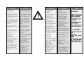
Safety Notes
To avoid injury of persons
and damage to the device,
it is absolutely necessary to
carefully read and observe
these Instructions.
Necessary assembly, start-
up, and maintenance work
may be performed only by
qualified and authorized
personnel.
Prior to assembly and
disassembly, depressurize
system!
Please comply with the
instructions of the system
manufacturer or system
operator.
Definition of
Application
The electrical actuator is
used in connection with the
following valves:
VFG 2(21), VFG 25, VFU 2,
VFGS 2, AFQM
Fields of application are the
temperature control of
water, water-glycol mixtures
and steam for heating,
district heating and cooling
systems.

4
AME (-H) 610, 613, 633
DEUTSCH
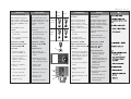
Übersicht
Stellantriebe AME ...
siehe Tabelle 1
Ventiltypen für
AME (-H) 6..
Der elektrische Stellantrieb
AME (-H) 6.. kann auf
folgende Ventile montiert
werden, siehe Tabelle 2.
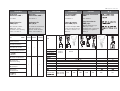
ENGLISH
Overview
Actuators AME ...
see table 1
Valve Types for
AME(-H) 6..
The electical actuator
AME(-H) 6.. can be
mounted on the following
valves, see table 2.
FRANCAIS
Vue d’ensemble
moteurs AME....
Voir tableau 1
Types de vannes
pour AME (-H) 6..
Le moteur électrique AME
(-H) 6.. peut être monté sur
les vannes suivantes, voir
tableau 2.
POLSKI
Przegl¹d si³owników
AME...
patrz Tabela 1
Typy zaworów do
AME(-H)6..
Si³ownik elektryczny typu
AME(-H) 6...mo¿e
wspó³pracowaæ z zaworami
regulacyjnymi, zgodnie z
Tabel¹ 2.
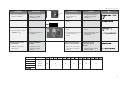
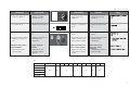
T2
Valve type VFG 2 VFG 2 VFU 2 VFGS2 AFQM
Ventiltyp VFG 21 VFG 21
Typ de vanne VFG 25
Typ zaworu
DN 15-125 150-250 15-125 - 150-250 15-125-150-250 65-125
PN 16, 25, 40 25
Medium Hot water Steam Hotwater
Medium Heisswasser Dampf Heisswasser
Fluide Eau chaude Vapeur Eau chaude
Czynnik Gor¹ca woda Para wodna Gor¹ca woda
VFG 2:200
Tmax Medium VFG 25:200 140 200 200 200 350 300 150
VFG 21:150
T1 AME 610/30 613/33 H 613/33
Safety function
Sicherheitsfunktion
Fonction de secours - + -
Funkcja bezpieczeñstwa
Mechanical adjustment
Mechanische
Handverstellung
Commande manuelle + - +
Méchanique
Regulacja
mechaniczna

5
AME (-H) 610, 613, 633
DEUTSCH
Montage
Zulässige Einbaulagen
Für Ventile:
VFG 2, VFG 21, VFG 25
VFU 2, AFQM
DN 15 - 80
Mediumstemperaturen
bis 120 °C:
Für Ventile:
VFG 2, VFG 21, VFG 25
VFU 2, AFQM
DN 100 - 250
und bei
DN 15 - 80,
Mediumstemperaturen
größer 120 °C.
Für Ventile VFGS 2
Dampf
FRANCAIS
Montage
Orientations de montage
autorisées
Pour vannes :
VFG2, VFG21, VFG25,
VFU2, AFQM
DN 15 - 80
Température du fluide
jusqu’à 120°C :
Pour vannes :
VFG2, VFG21, VFG25,
VFU2, AFQM
DN 100 – 250
et pour
DN 15-80,
si la température du fluide
est supérieure à 120°C :
Pour vannes VFGS2 Vapeur
POLSKI
Monta¿
Dopuszczalne pozycje
monta¿u
Dla zaworów:
VFG 2, VFG 21, VFG 25,
VFU 2, AFQM
DN 15 80
temperatura czynnika do
120
o
C
Dla zaworów:
VFG 2, VFG 21, VFG 25,
VFU 2, AFQM
DN 100 250
i
DN 15 80
gdy temperatura czynnika
jest wy¿sza od 120
o
C
Dla zaworów VFGS 2 para
wodna
ENGLISH
Mounting
Permissible Installation
Positions
For valves:
VFG 2, VFG 21, VFG 25
VFU 2, AFQM
DN 15 - 80
medium temperatures
up to 120 °C
For valves:
VFG 2, VFG 21, VFG 25
VFU 2, AFQM
DN 100 - 250
and for
DN 15 - 80,
medium temperatures
>120 °C.
For valves VFGS 2
steam
VFG 2 (21), (25)
VFU 2
AFQM
VFU 2
AFQM
VFG 2 (21), (25)
VFGS 2

6
AME (-H) 610, 613, 633
DEUTSCH
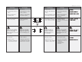
Einbau Ventil
1. Schmutzfänger vor dem
Ventil einbauen
2. Anlage vor dem Einbau
des Ventils spülen
3. Durchflussrichtung
➀ auf
dem Ventilgehäuse
beachten
Flansche
➁ in der Rohr-
leitung müssen parallel,
Dichtflächen sauber und
ohne Beschädigung sein.
4. Ventil einbauen
5. Schrauben über Kreuz
in 3 Stufen bis zum max.
Drehmoment anziehen
➁
FRANCAIS
Montage vanne
1. Monter le filtre devant la
vanne
2. Rincer l’installation avant
le montage de la vanne
3. Respecter le sens
d’écoulement
➀ indiqué
sur le corps de la vanne
Les brides ➁ dans la
tuyauterie doivent être
parallèles, les surfaces
d’étanchéité propres et
sans dommages.
4. Monter la vanne
5. Serrer les vis en 3
étapes en croix, jusqu’au
couple de rotation max.
POLSKI
Monta¿ zaworu
1. Zamontowaæ filtr przed
zaworem.
2. Przed zamontowaniem
zaworu przep³ukaæ
instalacjê.
3. Zwróciæ uwagê na
wskanik kierunku
przep³ywu
➀ na korpusie
zaworu.
Ko³nierze
➁ na ruroci¹gu
musz¹ byæ wzajemnie
równoleg³e, a powierzchnie
pod uszczelki czyste i bez
uszkodzeñ.
4. Zamontowaæ zawór.
5. Dokrêcaæ przeciwleg³e
nakrêtki w 3 krokach do
osi¹gniêcia
maksymalnego
momentu.
ENGLISH
Valve Installation
1. Install strainer in front of
valve.
2. Rinse system before
installing valve.
3. Observe flow direction
➀
on the valve body
Flanges
➁ in the pipeline
system must be in parallel
direction, the sealing
surfaces must be clean and
undamaged.
4. Install valve.
5. Tighten screws
crosswise in 3 steps up
to the maximum torque.
➀

7
AME (-H) 610, 613, 633
ENGLISH
Actuator and Valve
Installation
Before mounting:
1. Carry out the electrical
connection procedure
acc. to the next
paragraph
2. turn the rotary switch to
the postion “OPEN”
➀ to
run the actuator stem
➁
completely back
Valves DN 150 - 250
For valves DN 150 - 250 the
stem of the actuator must be
screwed into the valve stem.
Observe the Installation
Instructions attached to
valves DN 150 - 250.
Valves DN 15 - 125
1. Place actuator on the
valve and align.
2. Tighten union nut
➀
torque 100 Nm
DEUTSCH
Montage Stellantrieb und
Ventil
Vor der Montage:
1. “Elektrischen Anschluss
durchführen, siehe
nächsten Abschnitt
2. Drehschalter auf Stellung
“OPEN”
➀ drehen,
dadurch Antriebsstange
➁ ganz einfahren
Ventile DN 150 - 250
Bei den Ventilen
DN 150 - 250 muss die
Antriebstange in die Ventil-
stange eingeschraubt
werden.
Den Ventilen DN 150 - 250
beigefügte Montageanlei-
tung beachten.
Ventile DN 15 - 125
1. Stellantrieb am Ventil
ansetzen und
ausrichten
2. Überwurfmutter
➀
anziehen
Anzugsmoment 100 Nm
FRANCAIS
Montage moteur et vanne
Avant le montage :
1. Procéder au
branchement électrique,
voir prochain
paragraphe
2. Tourner le bouton rotatif
sur position “OPEN”
➀ ,
ainsi rétracter totalement
la tige du moteur
➁
Vannes DN150 - 250
Pour les vannes DN150-
250 la tige du moteur doit
être vissée dans la tige de
la vanne.
Respecter la notice de
montage jointe aux vannes
DN 150-250
Vannes DN15 - 125
1. Positionner le moteur sur
la vanne et procéder à
l’alignement
2. Serrer l’écrou prisonnier
➀,
facteur de serrage 100
Nm
POLSKI
Monta¿ si³ownika i zaworu
Przed monta¿em
1. Wykonaj po³¹czenia
elektryczne, patrz dalsza
czêæ instrukcji
2. Ustawiæ prze³¹cznik
obrotowy w pozycji
OPEN
➀, to
spowoduje ca³kowite
cofniêcie trzpienia
➁.
Dla zaworów DN 150 250
trzpieñ si³ownika musi
zostaæ wkrêcony w trzpieñ
zaworu.
Szczegó³y znaleæ mo¿na w
Instrukcji U¿ytkowania
zaworów DN 150 250
Dla zaworów DN 15 125
1. Umieciæ si³ownik na
zaworze.
2. Dokrêciæ nakrêtkê
³¹cz¹c¹
➀.
Moment: 100 Nm
DN 150 - 250
➀
46 mm
Instructions

8
AME (-H) 610, 613, 633
VFG(S)2 DN 150 - 250
t
max
300 °C
VFG(S).. DN 15 - 125
VFU 2
AME (-H) 6..
L
B
VFG(S).. DN 150 - 250
B
1
L
B
L
B
L
C
370
ø 175
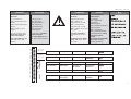
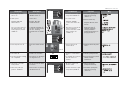
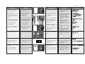
DEUTSCH
Isolierung
Abmessungen, Gewichte
Flansche Anschlussmasse
nach DIN 2501, Dichtleiste
Form C
FRANCAIS
Isolation
Dimensions, poids
Dimensions raccordement
à brides selon DIN 2501,
étanchéité forme C
POLSKI
Izolacja
Wymiary, wagi
Ko³nierze wymiary
po³¹czeñ zgodne z DIN
2501, uszczelka typu C
ENGLISH
Insulation
Dimensions, Weights
Flanges: Connection
dimensions acc. to DIN
2501, seal form C
DN 15 20 25 32 40 50 65 80 100 125 150 200 250
L mm 130 250 260 280 200 230 290 310 350 400 480 600 730
VFG 2 B 212 212 238 238 240 240 275 275 380 380 326 354 404
VFG21
VFG 25 kg 7 9 10 13 17 22 33 41 60 79 85 145 228
VFGS 2
VFG(S) B1 mm 630 855 1205
Tmax kg 140 210 300
300 B 95 95 106 106 123 123 135 135 165 165
VFU 2 C 311 311 337 337 339 339 374 374 479 479
kg 7 9 10 13 17 22 33 41 60 79

9
AME (-H) 610, 613, 633
POLSKI
Demonta¿ zaworu,
napêdu
Uwaga
Ryzyko poparzenia par¹
lub gor¹c¹ wod¹!
Zawór bez napêdu jest
otwarty
➀, uszczelnienie ➁
znajduje siê w napêdzie.
Przed demonta¿em nale¿y
bezwzglêdnie zrzuciæ
cinienie z uk³adu.
Kolejnoæ wykonywanych
czynnoci przy demonta¿u
odwrotna w stosunku do
kolejnoci podczas
monta¿u.
FRANCAIS
Démontage
Danger
Risques de brûlures par
l’eau chaude
La vanne n’est pas étanche
sans moteur
➀, le cône
d’étanchéité
➁ se trouve
dans l’écrou de fixation du
moteur.
Impérativement mettre
l’installation hors pression
avant tout démontage.
Pour le démontage suivre la
procédure de montage
dans le sens inverse.
ENGLISH
Disassembly of Valve,
Actuator
Danger
Danger of injury by steam
or hot water!
Valve without actuator is
open
➀, sealing ➁ is in the
actuator.
It is absolutely necessary to
depressurize system prior
to any work.
Carry out disassembly in
reverse order as assembly.
DEUTSCH
Demontage
Gefahr
Verletzungsgefahr durch
Heißwasser
Ventil ist ohne Antrieb
offen
➀, Abdichtung ➁
befindet sich im Antrieb.
Vor Demontage Anlage
unbedingt drucklos machen.
Demontage in umgekehr-ter
Reihenfolge wie die
Montage durchführen.
➁
➀
➁

10
AME (-H) 610, 613, 633
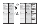
DEUTSCH
Elektrischer
Anschluss
Gefahr durch
Stromschlag!
Bei unsachgemäßer
Handhabung besteht
Lebens- oder
Verletzungsgefahr.
Vor dem Anschluss der
Leitungen unbedingt
Spannungsversorgung
abschalten.
Durchführung des
elektrischen Anschlusses
nur durch Elektrofachkraft.
Vorgehensweise
1. Schlitzschraube am
Drehschalter
➀ lösen,
Drehschalter abziehen
2. Schraube
➁
herausschrauben und
Deckel
➂ abnehmen
3. Leitungen nach dem
Anschlussplan
anschließen, siehe
nächste Seite
4. Vor Montage des
Deckels, Einstellungen
am Stellantrieb
durchführen, siehe
nächsten Abschnitt
➂
➀
➁
FRANCAIS
Branchement
électrique
Danger
d’électrocution !
Lors d’une manipulation
non appropriée, danger de
mort ou risques de
blessures
Avant le branchement des
câbles, impérativement
couper l’alimentation.
Le branchement doit être
effectué uniquement par du
personnel qualifié.
Procédure :
1. Desserrer la vis au
niveau du bouton rotatif
➀, retirer le bouton
2. Dévisser la vis
➁ et
retirer le capot
➂
3. Raccorder les câbles
selon le schéma de
branchement, voir page
suivante
4. Avant de remettre le
capot, effectuer les
réglages sur le moteur,
voir paragraphe suivant
POLSKI
Pod³¹czenie
elektryczne
WYSOKIE
NAPIÊCIE
Ryzyko obra¿eñ i
zagro¿enie ¿ycia w
przypadku nieprawid³owej
obs³ugi.
Przed wykonaniem
pod³¹czeñ elektrycznych
nale¿y bezwzglêdnie
wy³¹czyæ zasilanie.
Pod³¹czenia elektryczne
mog¹ byæ wykonane
wy³¹cznie przez
uprawnionego elektryka.
Tryb postêpowania
1. Zluzowaæ wkrêt w
prze³¹czniku obrotowym
➀, usun¹æ prze³¹cznik
obrotowy.
2. Odkrêciæ rubê
➁ i
usun¹æ obudowê
➂
3. Pod³¹czyæ przewody
zgodnie ze schematem
pod³¹czeñ elektrycznych -
patrz nastêpna strona
4. Przed za³o¿eniem
obudowy wykonaæ
wszystkie nastawy
si³ownika - patrz
nastêpny rozdzia³.
ENGLISH
Electrical
Connection
HIGH VOLTAGE !
Danger of injury and life in
case of improper handling.
Switch off power supply
prior to connecting lines.
The electrical connection
must only be performed by
an expert electrician.
Procedure
1. Loosen slotted screw at
the rotary switch
➀,
remove rotary switch.
2. Unscrew screw
➁ and
remove cover
➂.
3. Connect lines in
accordance with
connection diagram,
see next page.
4. Prior to remounting the
cover, carry out settings
at the actuator, see next
section.

11
AME (-H) 610, 613, 633
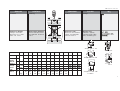
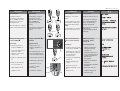
DEUTSCH
Elektrische Anschlussplan
➀ Anschluss für:
STB - Sicherheits-
temperaturbegrenzer
STW - Sicherheits-
temperaturwächter
SDB- Sicherheits-
druckbegrenzer
bei Anschluss unbedingt
Brücke entfernen
nur Typen AME (-H) 613,
633 mit Sicherheitsfunktion
FRANCAIS
Schéma de branchement
électrique
➀ Branchement pour :
STB – Limiteur de
température de sécurité
STW – Contrôleur de
température de sécurité
SDB – Limiteur de pression
de sécurité
Lors du branchement,
impérativement retirer le
pont
Uniquement types AME (-
H) 613, 633 avec fonction
de secours
POLSKI
Schemat pod³¹czeñ
elektrycznych
➀ zaciski do:
STB Ogranicznik
temperatury
bezpieczeñstwa
STW Stra¿nik temperatury
bezpieczeñstwa
SDB Ogranicznik
cinienia bezpieczeñstwa
Przed po³¹czeniem nale¿y
koniecznie usun¹æ
mostek.
dot. wy³¹cznie typów AME(-
H) 613, 633 z funkcj¹
sprê¿yny powrotnej.
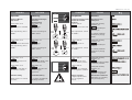
ENGLISH
Electrical Connection
Diagrams
➀ Connection for:
STB - Safety Temperature
Limiter
STW - Safety Temperature
Monitor
SDB - Safety Pressure
Limiter
Prior to connection it is
absolutely necessry to
remove the jumper
only types AME (-H) 613,
633 with safety return
function.
➀
PE
L
N
0(4)-20nA
0(2)-10V
GND
0(4)-20nA
0(2)-10V
0(4) - 20 mA
0(2) - 10 V
0(4) - 20 mA
0(2) - 10 V
➀
20
19
18
17
16
15
14
13
12
11
10
9
8
7
6
5
4
3
2
1
Output stroke Ausgang Hub Sortie Course Wejscie sterujace
Input controller Eingang regler Entrée régulateur Wyjscie sygnalu
polozenia
Power supply Spannungs Alimentation Napiêcie
versorgung zasilania
Valve Open Ventil auf Vanne ouverte Zawór otwarty
End switsches Endschalter Contacts fin Prze³¹czniki
de course krañcowe
Valve Closed Ventil zu Vanne fermée Zawór zamkniêty

12
AME (-H) 610, 613, 633
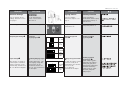
DEUTSCH
Einstellung
Stellantrieb
Vor den Einstellungen
Deckel
➀ demontieren,
siehe Seite 9
Schalterbezeichnungen
➁
Einstellung
Ausgangssignal
➂➂
➂➂
➂
Einstellung Eingangssignal
➃➃
➃➃
➃
Auswahl Spannungs- oder
Stromeingang erfolgt über
den Anschluss an der
Klemmleiste, Klemme 15
oder 16, siehe “Elektrischer
Anschlussplan”
➁➁
➁➁
➁
➀
FRANCAIS
Réglage moteur
Avant les réglages,
démonter le capot
➀, voir
page 9
Désignation des
commutateurs
➁
Réglage du signal de
sortie
➂➂
➂➂
➂
Réglage du signal d’entrée
➃➃
➃➃
➃
Le choix de l’entrée courant
ou tension se fait par le
branchement sur le bornier,
borne 15 ou 16,
voir «schéma de
branchement électrique»
POLSKI
Nastawy si³ownika
Przed wykonaniem
jakichkolwiek nastaw nale¿y
zdemontowaæ os³onê
➀
patrz strona 9.
Oznaczenia
mikroprze³¹czników
➁
Nastawy sygna³ów
wyjciowych
➂➂
➂➂
➂
Nastawy sygna³ów
wejciowych
➃➃
➃➃
➃
Wybór rodzaju sygna³u -
napiêciowy lub pr¹dowy -
dokonywany jest przez
odpowiednie pod³¹czenia
na listwie zaciskowej
zacisk 15 lub 16 patrz
Schemat pod³¹czeñ
elektrycznych.
ENGLISH
Actuator Settings
Prior to carrying out any
settings, dismount cover
➀,
see page 9.
Switch designations
➁
Output Signal Settings
➂➂
➂➂
➂
Input settings
➃➃
➃➃
➃
The selection of voltage or
current input is carried out
via the connection on the
terminal strip, terminal 15 or
16, see “Electrical diagram”.
4
4
➂
0-20-mA
0-10V
4-20 mA
2-10V
1 2
1 2
➂
0/2 - 10V
0 / 4 -
20 mA
S1
3
3
➃
0-20-mA
0-10V
4-20 mA
2-10V

13
AME (-H) 610, 613, 633
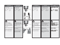
DEUTSCH
Einstellung der Endlagen
Nach der Montage Ventil
und Stellantreib müssen die
Endlagen “Ventil AUF” und
“Ventil ZU” eingestellt
werden.
Voraussetzung für die
Einstellung:
- der Stellantrieb ist auf
das Ventil montiert
- der elektrische
Anschluss ist erfolgt
Ventile VFG .., AFQM
Endlage “Ventil ZU”
➀➀
➀➀
➀
einstellen
Vorgehensweise
1. Drehschalter auf
Stellung “CLOSE”
➁
stellen
Hubanzeige
➂ muss
sich in Pfeilrichtung bis
zum Anschlag bewegen
➻ Ventil ist ganz
geschlossen
3. Hubanzeige ausrichten:
- Schrauben
➃ lösen
- Anzeige auf 0
ausrichten
➄
- Schrauben anziehen
➀
➁
OPEN
STOP
AUTO
STOP
CLOSE
➂
➃
➄
FRANCAIS
Réglage des positions fins
de course
Après le montage de la
vanne et du moteur, les
positions fins de course
«vanne ouverte» et «vanne
fermée» doivent être
réglées. Conditions pour le
réglage :
- le moteur est monté sur
la vanne
- le branchement
électrique est effectué
Vannes VFG..., AFQM
Régler la position fin de
course «vanne fermée»
➀➀
➀➀
➀
Procédure :
1. Tourner le bouton rotatif
sur position «CLOSE»
➁
L’indication de course ➂
doit se déplacer dans le
sens de la flèche
jusqu’en butée
➻ La vanne est totalement
fermée
3. Aligner l’indication de
course :
- Desserrer les vis
➃
- Aligner l’affichage sur 0
➄
- Serrer les vis
POLSKI
Nastawy pozycji
krañcowych
Po zamontowaniu zaworu i
si³ownika nale¿y ustawiæ
pozycje krañcowe Zawór
otwarty i Zawór zamkniêty.
Warunki wstêpne
wykonania nastaw to:
- si³ownik zamontowany na
zaworze,
- w pe³ni wykonane
pod³¹czenia elektryczne.
Zawory VFG..., AFQM
Ustawianie pozycji
krañcowej Zawór
zamkniêty
➀➀
➀➀
➀
Tryb postêpowania:
1. Ustawiæ prze³¹cznik
obrotowy w pozycji
CLOSE
➁.
Wskanik po³o¿enia
➂
musi przemieszczaæ siê
zgodnie z kierunkiem
strza³ki a¿ do
zatrzymania.
➻ Zawór jest ca³kowicie
zamkniêty.
3. Wyregulowaæ wskanik
po³o¿enia:
- poluzowaæ ruby
➃
- ustawiæ pozycjê 0 ➄.
- dokrêciæ ruby.
ENGLISH
Final Position Settings
After having mounted the
valves and the actuator, the
final positions “Valve OPEN”
and “Valve CLOSED” must
be set.
Pre-conditions for the
settings:
- the actuator is mounted
on the valve
- the electrical connection
is completed.
Valves VFG .., AFQM
Setting the final position
“Valve CLOSED”
➀➀
➀➀
➀
Procedure
1. Set rotary switch to
position “CLOSE”
➁.
The stroke indicator
➂
must move in the
direction of the arrow
up to its stop.
➻ Valve is completely
closed.
3. Align stroke indicator:
- Loosen screws
➃.
- Align display to 0
➄.
- Tighten screws.
074mA
072 V
20mA
10V
VFG..
AFQ
VFU

14
AME (-H) 610, 613, 633
DEUTSCH
4. Drehschalter um eine
Stellung, auf STOP,
weiterdrehen
➀
5. Schalter S2 einstellen ➁
6. Taste S4 einmal drücken
➂
➻ Endlage “Ventil ZU” ist
eingestellt
Endlage “Ventil AUF”
einstellen
1. Ventilhub aus der
folgenden Tabelle
ablesen
➂
FRANCAIS
4. Avancer le bouton rotatif
d’une position sur
“STOP”
➀
5. Régler le commutateur
S2
➁
6. Presser 1 fois la touche
S4
➂
➻ La position fin de course
«vanne fermée» est
réglée
Régler la position fin de
course «vanne ouverte»
1. Relever la course de la
vanne dans le tableau
suivant
POLSKI
4. Przestawiæ prze³¹cznik
obrotowy na pozycjê
STOP
➀.
5. Ustawiæ prze³¹cznik S2
➁.
6. Nacisn¹æ klucz S4 jeden
raz
➂.
➻ Pozycja krañcowa Zawór
zamkniêty zosta³a
nastawiona.
Ustawianie pozycji
krañcowej Zawór
otwarty.
1. Odczytaæ skok zaworu z
poni¿szej tabeli.
ENGLISH
4. Turn rotary switch by one
position to STOP
➀
5. Set switch S2 ➁
6. Press key S4 once ➂
➻ The final position “Valve
CLOSED” is set.
Setting the finalposition
“Valve OPEN”
1. Find the stroke in the
table below
1
➁➁
➁➁
➁
S2
➀
OPEN
STOP
AUTO
STOP
CLOSE
DN 15 20 25 32 40 50 65 80 100 125 150 200 250
Valve stroke VFG 2
Ventilhub VFG 21
Course vanne VFG 25 mm 6 8 12 18 20 24
Skok zaworu AFQM

15
AME (-H) 610, 613, 633
DEUTSCH
2. Drehschalter auf Stellung
“OPEN” drehen
➀
➻ Ventil öffnet
Beispiel: DN 100,
Ventilhub 20 mm
sobald der Ventilhub
➁
erreicht ist, Drehschalter
um eine Stellung
weiterdrehen auf “STOP”
➂
3. Taste S4 einmal drücken
➃
4. Schalter S2 einstellen
➻ Einstellung der Endlagen
ist abgeschlossen
5. Deckel und Drehschalter
montieren
6. Drehschalter auf Stellung
“AUTO” drehen
➄
➀
➁
OPEN
STOP
AUTO
STOP
CLOSE
1
S2
➂
OPEN
STOP
AUTO
STOP
CLOSE
➃
FRANCAIS
2. Tourner le bouton rotatif
sur position “OPEN”
➀
➻ La vanne ouvre
Exemple : DN100,
course de la vanne 20
mm
Dès que la course de la
vanne est atteinte,
avancer le bouton rotatif
d’une position sur
«STOP»
➂
3. Presser une fois la
touche S4
➃
4. Régler le commutateur
S2
➻ Le réglage des positions
fins de course est
terminé
5. Monter le capot et le
bouton rotatif
6. Tourner le bouton rotatif
sur position „AUTO“
➄
POLSKI
2. Przestawiæ prze³¹cznik
obrotowy na pozycjê
OPEN.
➀
➻ Zawór otwiera siê.
Przyk³ad: DN 100, skok
20 mm
Kiedy tylko skok
➁
zostanie osi¹gniêty,
nale¿y przestawiæ
prze³¹cznik obrotowy na
pozycjê STOP
➂.
3. Nacisn¹æ klucz S4 jeden
raz
➃.
4. Ustawiæ prze³¹cznik S2.
➻ Pozycja krañcowa Zawór
otwarty zosta³a
nastawiona.
5. Za³o¿yæ obudowê i
prze³¹cznik obrotowy.
6. Przestawiæ prze³¹cznik
obrotowy na pozycjê
AUTO
➄.
ENGLISH
2. Set rotary to position
“Close”
➀
➻ Valve opens
Example: DN 100,
Stroke 20 mm
As soon as the stroke
➁
has been reached , set
rotary switch to position
“STOP”
➂
3. Press key S4 once ➃
4. Set switch S2
➻ The final position settings
are completed.
5. Re-mount cover and
rotary switch
6. Turn rotary switch to
position “AUTO”
➄
OPEN
STOP
AUTO
STOP
CLOSE
➄

16
AME (-H) 610, 613, 633
DEUTSCH
Ventile VFU 2
Anmerkungen zu VFU 2:
Das Ventil VFU 2 hat
gegenüber den Ventilen
VFG .., AFQM eine
umgekehrte Schließ-
richtung.
Das Ventil VFU 2 wird durch
die Sicherheits-funktion
geöffnet.
Endlage “Ventil AUF”
➀➀
➀➀
➀
einstellen
Vorgehensweise
1. Drehschalter auf
Stellung “CLOSE”
➁
stellen
die Hubanzeige
➂ muss
sich in Pfeilrichtung bis
zum Anschlag bewegen
➻ Ventil ist ganz geöffnet
➃
3. Hubanzeige ausrichten:
- Schrauben
➄ lösen
- Anzeige auf 0
➅
ausrichten
- Schrauben anziehen
➂
➁
OPEN
STOP
AUTO
STOP
CLOSE
➃
➄
➅
VFG ..
AFQM
VFU 2
FRANCAIS
Vannes VFU2
Remarques concernant
VFU2 :
La vanne VFU2 a un sens
de fermeture contraire par
rapport aux vannes VFG...,
AFQM
La vanne VFU2 est ouverte
par la fonction de secours.
Régler la position fin de
course «vanne ouverte»
➀➀
➀➀
➀
Procédure :
1. Tourner le bouton rotatif
sur position «CLOSE»
➁
L’indication de course ➂
doit se déplacer dans le
sens de la flèche
jusqu’en butée
➻ La vanne est totalement
ouverte
➃
3. Aligner l’indication de
course :
- Desserrer les vis
➄
- Aligner l’affichage sur 0
➅
- Serrer les vis
POLSKI
Zawory VFU 2
Uwagi do zaworów VFU 2:
W stosunku do zaworów
VFG..., AFQM, zawór typu
VFU 2 ma odwrócony
kierunek zamykania.
Zawór VFU 2 jest otwierany
przez funkcjê
bezpieczeñstwa sprê¿yny
powrotnej .
Ustawianie pozycji
krañcowej Zawór
otwarty À
Tryb postêpowania
1. Ustawiæ prze³¹cznik
obrotowy w pozycji
CLOSE
➁ .
Wskanik po³o¿enia
➂
musi przemieszczaæ siê
zgodnie z kierunkiem
strza³ki a¿ do
zatrzymania.
➻ Zawór jest ca³kowicie
otwarty
➃.
3. Wyregulowaæ wskanik
po³o¿enia:
- poluzowaæ ruby
➄.
- ustawiæ pozycjê 0
➅ .
- dokrêciæ ruby.
ENGLISH
Valves VFU 2
Remarks to VFU 2:
In contrary to the valves
VFG .., AFQM , the valve
VFU 2 has a reversed
closing direction.
The valve VFU 2 is opened
by the safety return function.
Setting the final position
“Valve OPEN”
➀➀
➀➀
➀
Procedure
1. Set rotary switch to
position “CLOSE”
➁.
The stroke indicator
➂
must move in the
direction of the arrow
up to its stop.
➻ Valve is completely open
➃
3. Align stroke indicator:
- Loosen screws
➄.
- Align display to 0
➅.
- Tighten screws.

17
AME (-H) 610, 613, 633
DEUTSCH
4. Drehschalter um eine
Stellung auf STOP
weiterdrehen
➀
5. Schalter S2 einstellen ➁
6. Taste S4 einmal drücken
➂
➻ Endlage “Ventil AUF” für
Ventil VFU 2 ist
eingestellt
Endlage “Ventil ZU”
einstellen
1. Ventilhub aus der
folgenden Tabelle
ablesen
FRANCAIS
4. Avancer le bouton rotatif
d’une position sur
“STOP”
➀
5. Régler le commutateur
S2
➁
6. Presser 1 fois la touche
S4
➂
➻ La position fin de course
«vanne ouverte» pour
vanne VFU2 est réglée
Régler la position fin de
course «vanne fermée»
1. Relever la course de la
vanne dans le tableau
suivant
POLSKI
4. Przestawiæ prze³¹cznik
obrotowy na pozycjê
STOP
➀.
5. Ustawiæ prze³¹cznik S2
➁.
6. Nacisn¹æ klucz S4 jeden
raz
➂.
➻ Pozycja krañcowa Zawór
otwarty zosta³a
nastawiona.
Ustawianie pozycji
krañcowej Zawór
zamkniêty.
1. Odczytaæ skok zaworu z
poni¿szej tabeli.
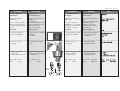
ENGLISH
4. Turn rotary switch by one
position to STOP
➀
5. Set switch S2 ➁
6. Pres key S4 once ➂
➻ The final positoin “Valve
OPEN” for valve VFU is
set.
Setting the final position
“Valve CLOSED”
1. Take stroke from the
following table.
T1
➀
OPEN
STOP
AUTO
STOP
CLOSE
1
➁➁
➁➁
➁
➂
DN 15 20 25 32 40 50 65 80 100 125
Valve stroke
Ventilhub
Course vanne VFU mm 6 8 12 18 20
Skok zaworu

18
AME (-H) 610, 613, 633
DEUTSCH
2. Drehschalter auf Stellung
“CLOSE” drehen
➀
➻ Ventil schließt (VFU 2),
die Hubanzeige
➁
bewegt sich in
Pfeilrichtung
3. die Hubanzeige bis zum
Anschlag fahren lassen,
auf der Skala  wird der
Ventilhub angezeigt
Beispiel: DN 100,
Ventilhub 20 mm
4. Drehschalter um eine
Stellung weiterdrehen
auf “STOP”
➃
5. Taste S4 einmal drücken
➄
6. Schalter S2 einstellen
➻ Einstellung der Endlagen
ist abgeschlossen
7. Deckel und Drehschalter
montieren
8. Drehschalter auf Stellung
“AUTO” drehen
➅
1
S2
➃
OPEN
STOP
AUTO
STOP
CLOSE
OPEN
STOP
AUTO
STOP
CLOSE
➀
➁
➂
➄
OPEN
STOP
AUTO
STOP
CLOSE
➅
FRANCAIS
2. Tourner le bouton rotatif
sur position “CLOSE”
➀
➻ La vanne ferme (VFU2),
l’indication de course
➁
se déplace dans le sens
de la flèche
3. Laisser aller l’indication
de course jusqu’en
butée. La course de la
vanne est indiquée sur
l’échelle
➂
Exemple : DN100, course
de la vanne 20 mm
4. Avancer le bouton rotatif
d’une position sur
«STOP»
➃
5. Presser 1 fois la touche
S4
➄
6. Régler le commutateur
S2
➻ Le réglage des positions
fins de course est
terminé
7. Monter le capot et le
bouton rotatif
8. Tourner le bouton rotatif
sur position “AUTO”
➅
POLSKI
2. Przestawiæ prze³¹cznik
obrotowy na pozycjê
CLOSE
➀.
➻ Zawór zamyka siê. Kiedy
tylko skok
➁ zostanie
osi¹gniêty, nale¿y
przestawiæ prze³¹cznik
obrotowy na pozycjê
STOP.
3. Wskanik po³o¿enia
podnosi siê do oporu,
skok zawór jest
przedstawiony na skali
➂.
Przyk³ad: DN 100, skok
20 mm
4. Przestawiæ prze³¹cznik
obrotowy na pozycjê
STOP
➃
5. Nacisn¹æ klucz S4 jeden
raz
➄.
6. Ustawiæ prze³¹cznik S2.
➻ Pozycja krañcowa Zawór
zamkniêty zosta³a
nastawiona.
7. Za³o¿yæ obudowê i
prze³¹cznik obrotowy.
8. Przestawiæ prze³¹cznik
obrotowy na pozycjê
AUTO
➅.
ENGLISH
2. Set rotary switch to
position “CLOSE”
➀
➻ Valve closes,
as soon as the stroke
➁
has ben reached, set
rotary switch to position
“STOP”.
3. Stroke indicator moves
up to its stop, the valve is
shown on the scale
➂
Example: DN 100,
stroke 20 mm
4. Turn rotary switch by one
position to “STOP”
➃
5. Pres key S4 once ➄
6. Set switch S2
➻ The setting of the final
positions is done
7. Mount cover and rotary
switch
8. Set rotary switch to
position “AUTO”
➅

19
AME (-H) 610, 613, 633
DEUTSCH
Bedienung
Drehschalterstellungen,
elektrische
Handverstellung
Drehschalter auf
Antriebsstange
fährt aus
➀
nach der Verstellung auf
“STOP” drehen
Drehschalter auf
Antriebsstange
fährt ein
➀
nach der Verstellung auf
“STOP” drehen
Drehschalter auf
Antriebsstange bleibt in der
letzten Position stehen
Drehschalter auf
Stellantrieb wird über den
externen Regler
angesteuert.
Standardeinstellung
für normalen Regelbetrieb
unbedingt einstellen
AUTO
OPEN
CLOSE
STOP
AUTO
OPEN
CLOSE
STOP
POLSKI
Dzia³anie
Regulacja rêczna -
elektryczna
Prze³¹cznik obrotowy
ustawiony na
Trzpieñ si³ownika jest
wysuwany
➀.
Po zmianie po³o¿enia,
przekrêciæ na pozycjê
STOP.
Prze³¹cznik obrotowy
ustawiony na
Trzpieñ si³ownika jest
cofany
➀.
Po zmianie po³o¿enia,
przekrêciæ na pozycjê
STOP.
Prze³¹cznik obrotowy
ustawiony na
Trzpieñ si³ownika pozostaje
w ostatnim po³o¿eniu.
Prze³¹cznik obrotowy
ustawiony na
Si³ownik sterowany jest
sygna³em z regulatora.
Standardowe ustawienie.
Stosowane do normalnej
pracy automatycznej.
ENGLISH
Operation
Electrical Manual
Adjustment
Rotary switch set to
Actuator stem is extended
➀:
After repositioning, turn to
“STOP”
Rotary switch set to
Actuator stem is retracted À:
After repositioning, turn to
“STOP”
Rotary switch set to
Actuator stem stays in its
last position.
Rotary switch set to
Actuator is controlled via
the external controller.
Standard setting
Strictly observe for normal
operation.
FRANCAIS
Manipulation
Positions du bouton rotatif,
commande manuelle
électrique
Bouton rotatif sur
La tige du moteur descend
➀
Après l’ajustement, tourner
sur «STOP»
Bouton rotatif sur
La tige du moteur se
rétracte
➀
Après l’ajustement, tourner
sur «STOP»
Bouton rotatif sur
La tige du moteur reste
dans sa dernière position
Bouton rotatif sur
Le moteur est commandé
par un régulateur extérieur
Réglage standard
A régler impérativement
pour une régulation
normale
STOP
AUTO
STOP
CLOSE
OPEN
➀
VFG ..
AFQ
VFU 2
➀
VFU 2
VFG ..
AFQ
STOP
AUTO
STOP
CLOSE
OPEN
AUTO
AUTO
CLOSE
OPEN
STOP
CLOSE
OPEN
STOP

20
AME (-H) 610, 613, 633
DEUTSCH
Mechanische
Handverstellungen
nur bei den Stellantrieben
AMV-H 613
Bei Ausfall der
Spannungsversorgung oder
bei einer Störung kann das
Ventil geöffnet oder
geschlossen werden
Vorgehensweise
1. Drehschalter auf Stellung
“OPEN”
drehen
➀
2. Sicherungsschraube ➁
lösen
3. Mittels Hakenschlüssel
(Zubehör) Antriebsstange
➂ einfahren
VFG .., AFQ öffnet
VFU 2 schließt
FRANCAIS
Commande manuelle
mécanique
Uniquement pour moteurs
AME-H 613
Lors d’une coupure de
l’alimentation ou lors d’une
perturbation, la vanne peut
être ouverte ou fermée
Procédure :
1. Tourner le bouton rotatif
sur position «OPEN»
➀
2. Desserrer la vis de
sécurité
➁
3. Rétracter la tige à l’aide
d’une clé à griffes
(accessoire)
➂
VFG..., AFQ ouvre
VFU2 ferme
POLSKI
Regulacja rêczna -
mechaniczna
tylko w si³ownikach AMV-H
613
W przypadku awarii ¿ród³a
zasilania lub b³êdu
dzia³ania, zawór mo¿e
zostaæ rêcznie otworzony
lub zamkniêty.
Tryb postêpowania
1. Przestawiæ prze³¹cznik
obrotowy na pozycjê
CLOSE
➀.
2. Poluzowaæ rubê
zabezpieczaj¹c¹
➁.
3. Przy pomocy klucza
(akcesoria) cofn¹æ
trzpieñ si³ownika
➂ .
VFG..., AFQ otwieranie
VFU 2 zamykanie
ENGLISH
Mechanical Manual
Adjustments
only for the actuators
AME-H 613
In case of a power supply
failure or a operating fault,
the valve may be opened or
closed
Procedure
1. Turn rotary switch to
position “CLOSE”
➀.
2. Loosen security
screw
➁.
3. With hook wrench
(accessory)
retract actuator stem
➂.
VFG .., AFQ opens
VFU 2 closes
OPEN
STOP
AUTO
STOP
CLOSE
➀
➁
VFU 2
AFQ
VFG ..
➂
Strona się ładuje...
-
 1
1
-
 2
2
-
 3
3
-
 4
4
-
 5
5
-
 6
6
-
 7
7
-
 8
8
-
 9
9
-
 10
10
-
 11
11
-
 12
12
-
 13
13
-
 14
14
-
 15
15
-
 16
16
-
 17
17
-
 18
18
-
 19
19
-
 20
20
-
 21
21


w innych językach
- Deutsch: Danfoss AME 610/613 Bedienungsanleitung
- français: Danfoss AME 610/613 Mode d'emploi
- English: Danfoss AME 610/613 Operating instructions
Powiązane artykuły
-
Danfoss AME 610/613 Instrukcja obsługi
-
-
-
-
-
-
-
-
-


