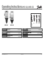
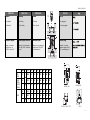
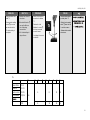
Strona się ładuje...

2
AME (-H) 410, 413
DEUTSCH
Inhalt
Sicherheitshinweise 3
Bestimmungsgemäße
Verwendung 3
Sicherheitsfunktion und
Wirkrichtung 4
Ventiltypen für AME ... 4
Montage 5
- Zulässige
Einbaulagen 5
- Einbau Ventil 6
- Montage Stellantrieb
und Ventil 7
- Isolierung 9
- Abmessungen,
Gewichte 9
Elektrischer Anschluss 10
Elektrischer
Anschlussplan 11
Mechanische
Hubeinstellung 12
Elektrische
Einstellungen 14
- Ausgangssignal 14
- Eingangssignal 15
- Einstellung der
Endlagen 15
Ventile VFG.., AFQM 15
Ventile VFU 2 17
- Zuordnung der
Wirkrichtung zum
Ein-, Ausgangssignal 20
Demontage 21
ENGLISH
Contents
Safety notes 3
Definition of application 3
Safety Function and
Effective Direction 4
Valve Types for
AME 41. 4
Mounting 5
- Permissible Installation
Positions 5
- Valve installation 6
- Actuator and Valve
Installation 7
- Insulation 9
Dimensions, Weights 9
Electrical Connection 10
Electrical Connection
Diagram 11
Mechanical Stroke
Setting 12
Actuator Electrical
Settings 14
- Setting the Output
Signal 14
- Setting the Input
Signal 15
- Setting the Final
Positions 15
Valves VFG.., AFQM 6 15
Valves VFU 2 17
- Assignment of the
effective direction
for the input and
output signals 20
Dismounting of Valve
and Actuator 21
POLSKI
Spis treci
Warunki bezpieczeñstwa 3
Zakres zastosowañ 3
Funkcja bezpieczeñstwa
sprê¿yny 4
Powrotnej, kierunek
dzia³ania 4
Typy zaworów do AME 41 4
Monta¿ 5
Dopuszczalne
pozycje monta¿u 5
Monta¿ zaworu 6
Monta¿ si³ownika i zaworu 7
Izolacja 9
Wymiary / Wagi 9
Pod³¹czenie elektryczne 10
Schemat
pod³¹czeñ elektrycznych 11
Nastawy
mechaniczne si³ownika 12
Nastawy elektryczne si³ownika 14
Nastawy
sygna³ów wyjciowych 14
Nastawy
sygna³ów wejciowych 15
Nastawy pozycji
krañcowych 15
Zawory VFG, AFQM6 15
Zawory VFU 2 17
Przypisanie kierunku
sygna³om wejciowemu i
wyjciowemu 20
Demonta¿ 21
FRANCAIS
Sommaire
Consignes de sécurité 3
Conditions d’utilisation 3
Fonction de secours et
sens de fonctionnement 4
Types de vannes pour
AME.... 4
Montage 5
- Orientations de
montage autorisées 5
- Montage vanne 6
- Montage moteur
et vanne 7
- Isolation 9
- Dimensions / poids 9
Branchement
électrique 10
Schéma de branchement
électrique 11
Réglage mécanique de la
course 12
Réglages électriques 14
- Signal de sortie 14
- Signal d’entrée 15
- Réglage des positions
fins de course 15
Vannes VFG..., AFQM 15
Vannes VFU2 17
- Affectation du sens de
fonctionnement au
signal d’entrée/sortie 20
Démontage 21
10

3
AME (-H) 410, 413
DEUTSCH
Sicherheitshinweise
Um Verletzungen an Perso-
nen und Schäden am Gerät
zu vermeiden, diese Anlei-
tung unbedingt beachten.
Montage, Inbetriebnahme
und Wartungsarbeiten
dürfen nur von sach-
kundigen und autorisierten
Personen durchgeführt
werden.
Anlage vor Montage,
Demontage unbedingt
drucklos machen.
Die Vorgaben des Anlagen-
herstellers und Anlagen-
betreibers sind zu
beachten.
Bestimmungsgemäße
Verwendung
Der elektrische Stellantrieb
wird in Verbindung mit
folgenden Ventilen
eingesetzt: VFG 2(21),
VFG 25, VFU 2, VFGS 2,
AFQM 6
Einsatzgebiete sind
Temperaturregelung von
Wasser, Wasser-
Glykolgemischen und
Dampf für Heizungs-,
Fernheizungs- und
Kühlungsanlagen.
ENGLISH
Safety Notes
To avoid injury of persons
and damage to the
device, it is absolutely
necessary to carefully
read and observe these
Instructions.
Necessary assembly,
start-up, and maintenance
work may be performed
only by qualified and
authorized personnel.
Prior to assembly and
disassembly,
depressurize system!
Please comply with the
instructions of the system
manufacturer or system
operator.
Definition of
Application
The electrical actuator is
used in connection with
the following valves:
VFG 2(21), VFG 25, VFU
2, VFGS 2, AFQM 6.
Fields of application are
the temperature control of
water, water-glycol
mixtures and steam for
heating, district heating
and cooling systems.
POLSKI
Warunki
bezpieczeñstwa
W celu unikniêcia ryzyka
zranienia osób i
uszkodzenia urz¹dzeñ
nale¿y bezwzglêdnie i
wnikliwie zapoznaæ siê z
niniejsz¹ instrukcj¹.
Niezbêdny monta¿,
uruchomienie oraz obs³uga
mog¹ byæ dokonywane
wy³¹cznie przez
wykwalifikowany i
autoryzowany personel.
Nale¿y bezwzglêdnie
zrzuciæ cinienie z uk³adu
przed monta¿em i
demonta¿em.
Prosimy stosowaæ siê do
instrukcji producenta i/lub
operatora uk³adu.
Zakres zastosowañ
Si³ownik elektryczny
stosowany jest w
po³¹czeniu z
nastêpuj¹cymi zaworami:
VFG 2(21), VFG 25, VFU 2,
VFGS 2, AFQM 6.
Znajduj¹ zastosowanie w
regulacji temperatury wody,
roztworu woda-glikol i pary
wodnej w uk³adach
grzewczych, instalacjach
sieci cieplnych i
ch³odzenia.
FRANCAIS
Consignes de
sécurité
Pour éviter les risques de
blessure pour les
personnes et les
dommages sur l’appareil,
lire attentivement cette
notice.
Le montage, la mise en
route et les travaux
d’entretien doivent être
effectués par du personnel
qualifié et autorisé.
Mettre impérativement
l’installation hors pression
avant tout montage ou
démontage.
Respecter les consignes du
fabricant de l’installation et
de l’exploitant de celle-ci.
Conditions
d’utilisation
Le servomoteur électrique
est utilisé en combinaison
avec les vannes suivantes :
VFG 2(21), VFG 25, VFU 2,
VFGS2, AFQM6
Domaines d’application :
régulation de la
température de l’eau, de
l’eau glycolée et de la
vapeur pour chauffage,
chauffage urbain et
installations de
réfrigération.

4
AME (-H) 410, 413
DEUTSCH
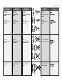
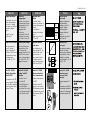
Sicherheitsfunktion
und Wirkrichtung
siehe Tabelle T1
Ventiltypen für
AME 41.
Der elektrische Stellantrieb
AME 41. kann auf folgende
Ventile montiert werden,
siehe Tabelle T2
ENGLISH
Safety Function and
Effective Direction
see table T1
Valve Types for
AME 41.
The electrical actuator
AME 41. can be mounted
on the following valves,
see table T2.
➀
POLSKI
Funkcja
bezpieczeñstwa
sprê¿yny powrotnej i
kierunek dzia³ania
patrz Tabela T1
Typy zaworów do
AME 41.
Si³ownik elektryczny typu AME
41. mo¿e wspó³pracowaæ z
zaworami regulacyjnymi,
zgodnie z Tabel¹ T2
FRANCAIS
Fonction de secours
et sens de
fonctionnement
Voir tableau 1
Types de vannes
pour AME 41.
Le moteur électrique AME
41. peut être monté sur les
vannes suivantes, voir
tableau 2
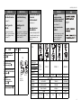
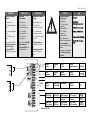
T2
Valve type
Ventiltyp
Typ de vanne
Typ zaworu
DN 15-80 15-80 15-80 15-80 40, 50
PN 16, 25, 40 25
Medium Hot water Steam Hotwater
Fluide Eau chaude Vapeur Eau chaude
Medium Heisswasser Dampf Heisswasser
T
max Medium
°C
VFG 2: 200
VFG 25:200 150 200 350 150
VFG 21:150
T1 AME 410 413
VFU 2
VFG ..
VFGS 2
AFQM 6
-+
Safety function and
effective direction of
stem
➀➀
➀➀
➀
Sicherheitsfunktion und
Wirkrichtung der
Antriebsstange
➀➀
➀➀
➀
Fonction de secours et
sens de fonctionnement
de la tige
➀➀
➀➀
➀
Funkcja
bezpieczeñstwa
i kierunek dzia³ania
trzpienia
➀➀
➀➀
➀
➀➀
➀➀
➀
VFG 2
VFG 21 VFU 2 VFGS 2 AFQM 6
VFG 25

5
AME (-H) 410, 413
DEUTSCH
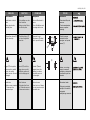
Montage
Zulässige Einbau-
lagen
DN 15 - 80
Mediumstemperaturen
bis 120 °C:
DN 15 - 80
Mediumstemperaturen
größer 120 °C:
Für Ventile VFGS 2
Dampf
ENGLISH
Mounting
Permissible Installation
Positions
DN 15 - 80
medium temperatures
up to 120 °C:
DN 15 - 80
medium temperatures
> 120 °C:
For valves VFGS 2
steam
POLSKI
Monta¿
Dopuszczalne pozycje
monta¿u
DN 15 80
temperatura czynnika
do 120
0
C
DN 15 80 temperatura
czynnika powy¿ej 120
0
C;
Dla zaworów VFGS 2
Czynnik para wodna
FRANCAIS
Montage
Orientations de montage
autorisées
DN 15 - 80
Température du fluide
jusqu’à 120°C :
DN 15 - 80
Température du fluide
supérieure à 120°C :
Pour vannes VFGS2
Vapeur
VFG 2 (21), (25)
VFU 2
AFQM 6
VFU 2
AFQM 6
VFG 2 (21), (25)
VFGS 2

6
AME (-H) 410, 413
DEUTSCH
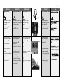
Einbau Ventil
1.Schmutzfänger vor dem
Ventil einbauen
2.Anlage vor dem Einbau
des Ventils spülen
3.Durchflussrichtung
➀
auf dem Ventilgehäuse
beachten
Flansche ➁ in der Rohr-
leitung müssen parallel,
Dichtflächen sauber und
ohne Beschädigung sein.
4.Ventil einbauen
5.Schrauben über Kreuz
in 3 Stufen bis zum max.
Drehmoment anziehen.
➀
➁
POLSKI
Monta¿ zaworu
1. Zamontowaæ filtr przed
zaworem.
2. Przed zamontowaniem
zaworu przep³ukaæ
instalacjê.
3. Zwróciæ uwagê na
wskanik kierunku
przep³ywu na korpusie
zaworu
➀.
Ko³nierze na ruroci¹gu
musz¹ byæ wzajemnie
równoleg³e, a powierzchnie
pod uszczelki czyste i bez
uszkodzeñ.
4.Zamontowaæ zawór.
5.Dokrêcaæ przeciwleg³e
nakrêtki w 3 krokach do
osi¹gniêcia
maksymalnego momentu.
ENGLISH
Valve Installation
1.Install strainer in front of
valve.
2.Rinse system before
installing valve.
3.Observe flow direction
➀
on the valve body.
Flanges ➁ in the pipeline
system must be in parallel
direction, the sealing
surfaces must be clean and
undamaged.
4.Install valve.
5.Tighten screws crosswise
in 3 steps up to the
maximum torque.
FRANCAIS
Montage vanne
1.Monter le filtre devant la
vanne
2.Rincer l’installation avant
le montage de la vanne
3.Respecter le sens
d’écoulement
➀ indiqué
sur le corps de la vanne
Les brides ➁ dans la
tuyauterie doivent être
parallèles, les surfaces
d’étanchéité propres et
sans dommages.
4.Monter la vanne
5.Serrer les vis en 3 étapes
en croix, jusqu’au couple
de rotation max.

7
AME (-H) 410, 413
DEUTSCH
Montage Stellantrieb und
Ventil
Der Stellantrieb darf nur mit
eingefahrener Schubstange
➀ montiert werden.
Hubanzeige ➁ muss in
Position ➁ stehen.
Bei Auslieferung ist die
Schubstange mittels
eingeschraubter
Montagechraube ➃
eingefahren.
Ist das nicht der Fall, dann :
1.elektrischen Anschluss
durchführen, siehe
nächsten Abschnitt
2. Taster
➂ drücken und
Schubstange ➀
vollständig einfahren
3.Montageschraube
➃ bis
zum Anschlag
einschrauben.
ENGLISH
Actuator and Valve
Installation
The actuator must only be
mounted with the stem
retracted ➀.
Stroke indicator ➁ must be
in position ➁.
On delivery the stem is
retracted with a screwed-in
mounting screw ➃.
If this is not the case,
then:
1.carry out the electrical
connection, see next
section,
2.press pushbutton
➃ and
completely retract the
stem ➀.
3.Screw in mounting screw
➃ up to its stop.
POLSKI
Monta¿ si³ownika i zaworu
Aby si³ownik móg³ byæ
zamontowany musi mieæ
cofniêty trzpieñ ➀.
Wskanik po³o¿enia ➁
musi byæ w pozycji ➁.
W przypadku dostawy
trzpieñ jest cofniêty i
zaplombowany rub¹
monta¿ow¹ ➃.
W przeciwnym wypadku:
1. wykonaæ po³¹czenie
elektryczne, patrz
nastêpny rozdzia³
2. nacinij przycisk
➂ do
ca³kowitego cofniêcia
trzpienia ➀
3. wkrêciæ rubê
monta¿ow¹ a¿ do
zatrzymania ➃.
➂
➀
➁
➃
FRANCAIS
Montage moteur et vanne
Uniquement monter le
moteur avec la tige ➀
rétractée.
L’indication de course ➁
doit être en position ➁
Lors de la livraison, la tige
est rétractée à l’aide de la
vis de montage ➃ qui est
vissée.
Si cela n’est pas les cas,
alors :
1.Procéder au branchement
électrique, voir prochain
paragraphe
2.Presser la touche
➂ et
rétracter totalement la tige
➀
3.Visser la vis de montage
➃ jusqu’en butée.

8
AME (-H) 410, 413
DEUTSCH
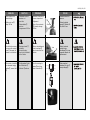
3.Stellantrieb am Ventil
ansetzen und
ausrichten
4.Überwurfmutter
➀
anziehen
Anzugsmoment 100 Nm
5.Montageschraube ➁
unbedingt
herausschrauben,
sonst ist der Stellantrieb
außer Funktion.
6.Bei hängendem Einbau
des Stellantriebs ➂
Aufkleber ➃ entfernen.
➀
46 mm
➂
➁
3 mm
➃
ENGLISH
3.Place actuator on the
valve and align.
4.Tighten union nut
➀
torque 100 Nm
5.It is absolutely necessary
to unscrew the mounting
screw ➁, otherwise, the
actuator is out of function.
6.If the actuator is installed
in a downward hanging
position ➂, remove label
➃.
POLSKI
3.Umieciæ si³ownik na
zaworze
4.Dokrêciæ nakrêtkê
³¹cz¹c¹
➀. Moment 35
Nm, klucz 36 mm
5.Nale¿y koniecznie
wykrêciæ rubê
monta¿ow¹ ➁ w innym
przypadku si³ownik nie
bêdzie dzia³a³.
6.Kiedy napêd jest
skierowany do do³u ➂
usun¹æ nalepkê ➃.
FRANCAIS
3.Positionner le moteur sur
la vanne et procéder à
l’alignement
4.Serrer l’écrou prisonnier
➀, facteur de serrage
100 Nm
5.Dévisser impérativement
la vis de montage ➁,
sinon le moteur est hors
fonction.
6.Lors d’un montage du
moteur ➂ vers le bas,
retirer l’autocollant ➃.

9
AME (-H) 410,413
DEUTSCH
Isolierung
➀ zulässig
➁ unzulässig
Abmessungen, Gewichte
Flansche Anschlussmaße
nach DIN 2501, Dichtleiste
Form C
VFU 2
ENGLISH
Insulation
➀ acceptable
➁ intolerable
Dimensions, Weights
Flanges: connection
dimensions acc. to
DIN 2501, seal form C
VFG(S).. DN 15 - 125
➀
➁
POLSKI
Izolacja
➀ do przyjêcia
➁ nie do przyjêcia
Rozmiar, Waga
Ko³nierze wymiary
po³¹czeñ zgodne z DIN
2501, uszczelka typu C.
B
L
AMV(E) 413
B
L
C
235
14 5
285
14 5
125
AMV(E) 410
DN 15 20 25 32 40 50 65 80
VFG.. L 130 250 260 280 200 230 290 310
VFU 2
VFG 2 B 212 212 238 238 240 240 275 275
VFG21
VFG 25 kg 7 9 10 13 17 22 33 41
VFGS 2
B 95 95 106 106 123 123 135 135
VFU 2 C 311 311 337 337 339 339 374 374
kg 7 9 10 13 17 22 33 41
mm
mm
FRANCAIS
Isolation
➀ Autorisé
➁ Non autorisé
Dimensions, poids
Dimensions raccordement
à brides selon DIN 2501,
étanchéité forme C

10
AME (-H) 410, 413
DEUTSCH
Elektrischer
Anschluss
Gefahr durch
stromschlag!
Bei unsachgemäßer
Handhabung besteht
Lebens- oder
Verletzungsgefahr.
Vor dem Anschluss der
Leitungen unbedingt
Spannungsversorgung
abschalten.
Durchführung des
elektrischen Anschlusses
nur durch Elektrofachkraft.
Vorgehensweise
1.Hutmutter ➀
abschrauben und Haube
➁ abnehmen
2.Leitungen nach dem
Anschlussplan
anschließen,
siehe nächste Seite
3.Vor Montage der Haube,
Einstellungen am
Stellantrieb durchführen,
siehe nächsten Abschnitt
ENGLISH
Electrical
Connection
HIGH VOLTAGE !
Danger of injury and life
in case of improper
handling.
Switch off power supply
prior to connecting lines.
The electrical connection
must only be performed by
an expert electrician.
Procedure
1.Unscrew cap nut ➀ and
remove cover ➁.
2.Connect lines in
accordance with
connection diagram,
see next page.
3.Prior to remounting the
cover, carry out settings at
the actuator,
see next section.
POLSKI
Pod³¹czenie
elektryczne
WYSOKIE NAPIÊCIE !
Ryzyko obra¿eñ i
zagro¿enie ¿ycia w
przypadku nieprawid³owej
obs³ugi.
Przed wykonaniem
pod³¹czeñ elektrycznych
nale¿y bezwzglêdnie
wy³¹czyæ zasilanie.
Pod³¹czenia elektryczne
mog¹ byæ wykonane
wy³¹cznie przez
uprawnionego elektryka.
Tryb postêpowania
1.Odkrêciæ rubê ➀ i
usun¹æ obudowê ➁.
2.Pod³¹czyæ przewody
zgodnie ze schematem
pod³¹czeñ elektrycznych -
patrz nastêpna strona.
3.Przed za³o¿eniem
obudowy wykonaæ
wszystkie nastawy
si³ownika - patrz nastêpny
rozdzia³.
➀
➁
FRANCAIS
Branchement
électrique
Danger
d’électrocution
Lors d’une manipulation
non appropriée, danger de
mort ou risques de
blessures.
Avant le branchement des
câbles, impérativement
couper l’alimentation.
Le branchement doit être
effectué uniquement par du
personnel qualifié.
Procédure :
1.Dévisser l’écrou du capot
➀ et retirer le capot ➁
2.Raccorder les câbles
selon le schéma de
branchement, voir page
suivante
3.Avant de remettre le
capot, effectuer les
réglages sur le moteur,
voir paragraphe suivant

11
AME (-H) 410,413
DEUTSCH
Elektrischer
Anschlussplan
➀ Anschluss für:
STB - Sicherheits-
temperaturbegrenzer
STW - Sicherheits-
temperaturwächter
SDB- Sicherheits-
druckbegrenzer
bei Anschluss unbedingt
Brücke entfernen
nur Typen AME 413 mit
Sicherheitsfunktion.
➀
+
+
+
-
-
ENGLISH
Electrical Connection
Diagram
➀ Connection for:
STB - Safety Temperature
Limiter
STW - Safety Temperature
Monitor
SDB - Safety Pressure
Limiter
Prior to connection, it is
absolutely necessary to
remove the jumper
only types AME 413
with safety return function.
-
+
+
0(4) - 20 mA
-
+
+
0(2) - 10 V
POLSKI
Schemat pod³¹czeñ
elektrycznych
➀ Zaciski do:
STB Ogranicznik
temperatury
bezpieczeñstwa
STW Stra¿nik
temperatury
bezpieczeñstwa
SDB Ogranicznik
cinienia bezpieczeñstwa
Przed po³¹czeniem
nale¿y koniecznie usun¹æ
mostek.
dot. wy³¹cznie typów AME
413 z funkcj¹ sprê¿yny
powrotnej.
0(4) - 20 mA
0(2) - 10 V
0(4) - 20 mA
0(2) - 10 V
AME 410, AME 413
PE
24 VAC
Power Spannungs Alimentation Napiêcie
supply versorgung zasilania
Output Ausgang Sortie Wyjscie
stroke Hub Course sygnalu polozenia
Input Eingang Entrée Wejscie
controller regler régulateur sterujace
Valve closed Ventil zu Vanne fermée Zawór zamkniêty
(VFU2 Open) (VFU2 Auf) (VFU2 ouverte) (VFU 2 otwarty)
End switsches Endschalter Contacts fin Prze³¹czniki
de course krañcowe
Valve Open Ventil Auf Vanne ouverte Zawór otwarty
(VFU2 closed) (VFU2 zu) (VFU2 fermée) (VFU2 zamkniêty)
VFU2
VFU2
FRANCAIS
Schéma de branchement
électrique
➀ Branchement pour :
STB – Limiteur de
température de sécurité
STW – Contrôleur de
température de sécurité
SDB – Limiteur de pression
de sécurité
Lors du branchement,
impérativement retirer le
pont
Uniquement types AME
413 avec fonction de
secours.

12
AME (-H) 410, 413
DEUTSCH
Mechanische
Hubeinstellung
Der Hub des elektrischen
Stellantriebs muss dem
Ventilhub angepasst
werden.
1.Falls noch nicht
durchgeführt, die
Montageschraube
➀
herausschrauben.
2.Taster ➁ drücken bis das
Ventil ➂ ganz
geschlossen (VFU 2 ➃
ganz geöffnet) ist und die
Lauf-richtungsanzeige ➄
zum Stillstand kommt.
Hubanzeige beachten,
sie muss bis Position
➅
fahren.
3.Hubeinstellschraube ➆
bis zum Anschlag
eindrehen.
ENGLISH
Mechanical Stroke
Setting
The stroke of the electrical
actuator must be adjusted
to the valve stroke.
1.If not yet done, unscrew
the mounting screw
➀.
2.Press pushbutton ➁ until
the valve ➂ is completely
closed (compl. open VFU
2 ➃) and the direction
indicator ➄ stops.
Observe stroke indicator,
it must move to position
➅.
3.Screw in stroke setting
screw ➆ up to its stop.
POLSKI
Nastawy skoku
mechanicznego
Skok si³ownika
elektrycznego musi byæ
przystosowany do skoku
zaworu.
1.Je¿eli nie jest to jeszcze
zrobione, odkrêciæ rubê
monta¿ow¹
➀.
2.Wcisn¹æ przycisk a¿ do
ca³kowitego zamkniêcia
zaworu ➁ (VFU 2 ➃
ca³kowitego otwarcia) i
do zatrzymania
wskanika poziomu ➄.
Obserwowaæ wskanik
poziomu, musi osi¹gn¹æ
pozycjê
➅.
3.Dokrêciæ rubê nastawy
skoku , a¿ do jej
zatrzymania.
➁
➀
3 mm
➂
➃ VFU 2
➆
➄
➅
FRANCAIS
Réglage mécanique
de la course
La course du moteur doit
être adaptée à la course
de la vanne.
1.Si cela n’est pas fait,
dévisser la vis de
montage
➀.
2.Presser la touche ➁
jusqu’à ce que la vanne
➂ soit totalement fermée
(VFU2 ➃ totalement
ouverte), et l’indicateur
de sens de
fonctionnement ➄ soit
arrêté.
Observer l’indication de
course, elle doit aller
jusqu’en position
➅.
3. Serrer la vis de réglage
de course ➆ jusqu’en
butée

13
AME (-H) 410, 413
DEUTSCH
4. Ventilhub aus Tabelle T1
entnehmen
5.Hubeinstellschraube
➆
pro mm Ventilhub um
eine Umdrehung
herausdrehen
➻ Die Hubeinstellung ist
abgeschlossen
ENGLISH
4. Take valve stroke from
table T1.
5.Unscrew stroke setting
screw
➆ by one turn
per mm valve stroke.
➻The stroke setting is
completed.
POLSKI
4. Odczytaæ skok zaworu z
poni¿szej tabeli T1
5. Odkrêciæ rubê nastawy
skoku
➆ jeden obrót na
1 mm skoku zaworu.
➻ Nastawa skoku zosta³a
zakoñczona.
➆
FRANCAIS
4. Relever la course de la
vanne dans le tableau
T1
5. Dévisser la vis de
limitation de course
➆
d’un tour par mm de
course de vanne
➻ Le réglage de la course
est terminé
Valve stroke VFG 2
Ventilhub VFG 21
Course vanne VFG 25 6 8 12 18
Skok zaworu AFQM 6 mm
VFU2 8 10 14 20
T1
DN 15 20 25 32 40 50 65 80

14
AME (-H) 410, 413
DEUTSCH
Elektrische
Einstellungen am
Stellantrieb
Vor der Inbetriebnahme
müssen die Einstellungen
für die Ein-,
Ausgangssignale und für
die Endlagen durchgeführt
werden.
Vor den Einstellungen die
Haube ➀ demontieren.
Schalterbezeichnungen
➁ Taster S1
➂ Schalter S2
Schalter 5, 6
Schalter 5 muss auf “OFF”
stehen.
Schalter 6 hat keine
Funktion.
Einstellung
Ausgangssignal
➃➃
➃➃
➃
Das Ausgangsignal ist
proportional zum Stellhub.
Einstellung des Schalters
S2 siehe Tabelle.
ENGLISH
Actuator Electrical
Settings
Prior to commissioning,
the settings for the input
und output signals and for
the final positions must be
carried out.
Prior to any settings,
dismount the cover ➀.
Switch Designations
➁ Pushbutton S1
➂ Switch S2
Switches 5, 6
Switch 5 must be on “OFF”.
Switch 6 has no function.
Setting the Output Signal
➃➃
➃➃
➃
The output signal is
proportional to the actuating
stroke.
Setting of the switch S2,
see table.
POLSKI
Nastawy elektryczne
si³ownika
Przed oddaniem do
eksploatacji musz¹ byæ
przeprowadzone nastawy
sygna³ów wyjciowych i
wejciowych jak równie¿
pozycji krañcowych.
Przed dokonaniem nastaw
zdj¹æ pokrywê
➀.
Oznaczenie wy³¹czników
➁ przycisk S1
➂ prze³¹cznik S2
Prze³¹czniki 5,6
Prze³¹cznik 5 musi byæ w
pozycji OFF.
Prze³¹cznik 6 jest
niewykorzystany.
Nastawa sygna³u
wyjciowego
➃➃
➃➃
➃
Sygna³ wyjciowy jest
proporcjonalny do ruchu
trzpienia.
Nastawy prze³¹czników S2,
patrz tabela
ON
OFF
5
6
➀
➀
➁
➂
ON
OFF
4
7 8
ON
OFF
4
7 8
ON
OFF
4
7 8
ON
OFF
4
7 8
➃
S2
0-20 mA
4-20 mA
0-10 V
2-10V
FRANCAIS
Réglages électriques
sur le moteur
Avant la mise en route,
procéder aux réglages pour
les signaux d’entrée et de
sortie, et les positions fins
course.
Avant les réglages,
démonter le capot
➀.
Désignation des
commutateurs
➁ Touche S1
➂ Interrupteur S2
Interrupteurs 5,6
L’interrupteur 5 doit être sur
«OFF».
L’interrupteur 6 n’a pas de
fonction.
Réglage du signal de
sortie
➃➃
➃➃
➃
Le signal de sortie est
proportionnel au réglage
de la course.
Réglage de l’interrupteur
S2, voir tableau.

15
AME (-H) 410, 413
DEUTSCH
Einstellung
Eingangssignal
Durch den Anschluss an
der Klemmleiste wird das
Eingangssignal “Strom”
oder “Spannung”
festgelegt, siehe
“Elektrischer
Anschlussplan” Seite 11
Einstellung von 0 oder 4
mA, 0 oder 2 V siehe ➀.
Einstellung der Endlagen
Nach Durchführung der
Hubeinstellung (siehe
S. 12) müssen die
Endlagen “Ventil AUF” und
“Ventil ZU” noch mit den
Strom-, Spannungswerten
0(4) - 20 mA, 0(2) - 10 V
abgeglichen werden.
Ventile VFG.., AFQM 6
Endlage “ Ventil ZU”
einstellen
1.Schalter 1 und 2
einstellen
➁.
2.Taster ➂ drücken bis
das Ventil ➃ ganz
geschlossen ist und die
Lauf-richtungsanzeige ➄
zum Stillstand kommt
ENGLISH
Setting the Input Signal
Connecting the lines to the
terminal strip determines
the “current” or “voltage”
input signal, see “Electrical
Connection Diagram”,
page 11.
Setting of 0 or 4 mA,
0 or 2 V, see
➀.
Setting the Final Positions
When the stroke is set
(see p. 12), the final
positions “Valve OPEN”
and “Valve CLOSED” must
be equalized with current
and voltage values
0(4) - 20 mA, 0(2) - 10 V.
Valves VFG.., AFQM 6
Setting the final position
“Valve CLOSED”
1.Set switches 1 and 2
➁.
2.Press pushbutton
➂ until
the valve ➃ is completely
closed and the direction
indicator ➄ stops.
POLSKI
Nastawa sygna³u
wejciowego
Pod³¹czyæ przewody do
listwy zaciskowej
okrelaj¹c pr¹d lub
napiêcie sygna³u
wejciowego patrz
Schemat elektryczny
strona 11.
Ustawienie 0 lub 4mA, 0
lub 2V, patrz ➀.
Nastawa pozycji
krañcowych
Kiedy skok jest ustawiony
(patrz str. 12), nale¿y
zrównaæ pozycje krañcowe
Zawór otwarty i Zawór
zamkniêty z wartoci¹
pr¹du i napiêcia 0 (4) 20
mA, 0(2) 10V.
Zawory VFG..,, AFQM
Ustawienie pozycji
krañcowej Zawór
zamkniêty
1.Ustaw prze³¹cznik 1i 2
➁
2.Naciskaæ przycisk ➂ do
ca³kowitego zamkniêcia
zaworu ➃ i zatrzymania
wskanika poziomu ➄
➂
ON
OFF
1
2
➁
0 100 %
0 (2, 4)
20 mA
10 V
➄
➃
ON
OFF
3
ON
OFF
3
➀
S2
0-20-mA
0-10V
4-20 mA
2-10V
Stroke
Hub
Course
Skok
FRANCAIS
Réglage du signal
d’entrée
Le choix de l’entrée
«courant» ou «tension» se
fait par le branchement sur
le bornier,
voir «schéma de
branchement électrique»
page 11
Réglage de 0 ou 4 mA, 0
ou 2 V, voir ➀.
Réglage des positions
fins de course
Après le réglage de la
course (voir page 12), les
positions fins de course
«vanne ouverte» et
«vanne fermée» doivent
être alignées avec les
valeurs courant et tension
0(4)-20 mA et 0(2)-10V.
Vannes VFG..., AFQM6
Régler la position fin de
course «vanne fermée»
1.Régler les interrupteurs
1 et 2
➁.
2.Presser la touche ➂
jusqu’à ce que la vanne
➃ soit totalement fermée
et l’indicateur de sens de
fonctionnement ➄ soit
arrêté

16
AME (-H) 410, 413
DEUTSCH
3.Taster ➀ drücken
➻ Endlage “Ventil ZU” ist
eingestellt
Endlage “Ventil AUF”
einstellen
1.Schalter 1 und 2
einstellen
➁
2.Taster ➂ drücken bis
das Ventil ➃ ganz
geöffnet ist und die.
Laufrichtungsanzeige ➄
zum Stillstand kommt
3.Taster ➅ drücken
➻ Endlage “Ventil AUF” ist
eingestellt
4.Schalter 1 auf
Standardeinstellung
stellen
➆
ON
OFF
1 2
➁
➂
➃
ON
OFF
1
2
➀
ON
OFF
1
2
➅
➄
ON
OFF
1
➆
ENGLISH
3.Press pushbutton ➀.
➻ The final position “Valve
CLOSED” is set.
Setting the final position
“Valve OPEN”
1.Set switches 1 and 2
➁.
2.Press pushbutton ➂ until
the valve ➃ is completely
open and the direction
indicator ➄ stops.
3.Press pushbutton ➅.
➻ The final position “Valve
OPEN” is set.
4.Set switch 1 to standard
mode
➆.
POLSKI
3.Nacisn¹æ przycisk ➀
➻ Pozycja krañcowa
Zawór zamkniêty
zosta³a nastawiona.
Ustawienie pozycji
krañcowej Zawór
otwarty
1.Ustaw prze³¹cznik 1i 2
➁
2.Naciskaæ przycisk ➂ do
ca³kowitego otwarcia
zaworu ➃ i zatrzymania
wskanika poziomu ➄
3. Nacisn¹æ przycisk ➅
➻ Pozycja krañcowa
Zawór otwarty zosta³a
nastawiona.
4.Nastawiæ prze³¹cznik 1
na tryb standardowy
➆.
➻
➻
FRANCAIS
3.Presser la touche ➀
➻ La position fin de course
«vanne fermée» est
réglée
Régler la position fin de
course «vanne ouverte»
1.Régler les interrupteurs 1
et 2
➁
2.Presser la touche ➂
jusqu’à ce que la vanne
➃ soit totalement ouverte
et l’indicateur de sens de
fonctionnement ➄ soit
arrêté
3.Presser la touche ➅
➻
La position fin de course
«vanne ouverte» est
réglée
4.Positionner l’interrupteur
1 sur réglage standard
➆

17
AME (-H) 410, 413
DEUTSCH
5.Hubbegrenzungs-
schraube ➀ um eine
Umdrehung
herausdrehen
➻ Einstellung der
Endlagen für Ventile
VFG.., AFQM 6 ist
abgeschlossen
6.Zuordnung der
Wirkrichtung zum Ein-,
Ausgangssignal
einstellen, siehe S. 20
Einstellung der Endlagen
Ventile VFU 2
Das Ventil VFU 2
➁ hat
gegenüber den Ventilen
VFG.., AFQM 6 eine
umgekehrte
Schließrichtung.
Das Ventil VFU 2 wird durch
die Sicherheitsfunktion
geöffnet.
➀
➁ VFU 2
➂ VFG..,
AFQM 6
ENGLISH
5.Unscrew the stroke
limiting screw ➀ by one
turn.
➻ The setting of the final
positions for the valves
VFG.., AFQM 6 is
completed.
6.Set the assignment of the
effective direction for the
input and output signals,
see p. 20
Setting the Final Positions
for valves VFU 2
In contrary to the valves
VFG .., AFQM6, the valve
VFU 2
➁ has a reversed
closing direction.
The valve VFU 2 is opened
by the safety return function.
POLSKI
5.Odkrêciæ rubê nastawy
skoku ➀ jeden obrót.
➻ Nastawa pozycji
krañcowych dla
zaworów VIM2, VIS2,
AIQM zosta³a
zakoñczona.
6.Ustawiæ przypisanie
kierunku sygna³om
wejciowemu i
wyjciowemu patrz str.
20
Nastawa pozycji
krañcowych dla zaworów
VFU 2
W przeciwieñstwie do
zaworów VFG.., AFQM 6
zawór VFU 2
➁ ma
odwrotny kierunek
zamykania.
Zawór VFU2 jest otwierany
przez funkcjê
bezpieczeñstwa sprê¿yny
powrotnej.
➻
FRANCAIS
5.Dévisser la vis de
limitation de course ➀
d’un tour.
➻ Le réglage des positions
fins de course pour vanne
VFG..., AFQM 6 est
terminé
6. Régler l’affectation du
sens de fonctionnement
au signal d’entrée/sortie,
voir page 20
Régler les positions fins
de course pour vannes
VFU2
La vanne VFU 2
➁ a un
sens de fermeture contraire
par rapport aux vannes
VFG..., AFQM 6
La vanne VFU 2 est ouverte
par la fonction de secours.

18
AME (-H) 410, 413
DEUTSCH
Endlage “ Ventil AUF” (VFU
2) einstellen
1.Schalter 1 und 2
einstellen ➀
2.Taster ➁ drücken bis
das Ventil ➂ ganz
geöffnet ist und die Lauf-
richtungsanzeige ➃ zum
Stillstand kommt
3.Taster ➄ drücken
➻ Endlage “Ventil AUF”
(VFU 2) ist eingestellt
Endlage “ Ventil ZU”
(VFU 2) einstellen
1.Schalter 1 und 2
einstellen
➅
ENGLISH
Setting the final position
“Valve OPEN” (VFU 2)
1.Set switches 1 and 2 ➀.
2.Press pushbutton
➁ until
the valve ➂ is completely
open and the direction
indicator ➃ stops.
3.Press pushbutton ➄.
➻ The final position “Valve
OPEN” (VFU 2) is set.
Setting the final position
“Valve CLOSED” (VFU 2)
1.Set switches 1 and 2
➅
POLSKI
Ustawienie pozycji
krañcowej Zawór
otwarty (VIU 2)
1.Ustaw prze³¹cznik 1i 2 ➀
2.Naciskaæ przycisk ➁ do
ca³kowitego otwarcia
zaworu ➂ i zatrzymania
wskanika poziomu ➃
3.Nacisn¹æ przycisk ➄
➻ Pozycja krañcowa
Zawór otwarty (VFU2)
zosta³a nastawiona.
Ustawienie pozycji
krañcowej Zawór
zamkniêty (VFU 2)
1.Ustaw prze³¹cznik 1 i 2
➅
ON
OFF
1
2
➀
➁
➂
VFU 2
➃
ON
OFF
1
2
➄
ON
OFF
1 2
➅
➻
FRANCAIS
Régler la position fin de
course “vanne ouverte”
(VFU2)
1.Régler les interrupteurs 1
et 2 ➀
2.Presser la touche ➁
jusqu’à ce que la vanne
➂ soit totalement ouverte
et l’indicateur de sens de
fonctionnement ➃ soit
arrêté
3.Presser la touche ➄
➻ La position fin de course
«vanne ouverte» (VFU2)
est réglée
Régler la position fin de
course «vanne fermée»
(VFU2)
1.Régler les interrupteurs 1
et 2
➅

19
AME (-H) 410, 413
DEUTSCH
2.Taster ➀ drücken bis
das Ventil ➁ ganz
geschlossen ist
und die Lauf-
richtungsanzeige ➂ zum
Stillstand kommt
3.Taster
➃ drücken
➻ Endlage “Ventil AUF” ist
eingestellt
4.Schalter 1 einstellen
➄
➻ Einstellung der Endlagen
für Ventile VFU 2 ist
abgeschlossen
5.Zuordnung der
Wirkrichtung zum Ein-,
Ausgangssignal
einstellen, siehe S. 20
ENGLISH
2.Press pushbutton ➀ until
the valve ➁ is completely
closed and the direction
indicator ➂ stops.
3.Press pushbutton
➃.
➻ The final position “Valve
OPEN” is set.
4.Set switch 1
➄
➻ The setting of the final
positions for the valves
VFU 2 is completed.
5.Set the assignment of the
effective direction for the
input and output signals,
see p. 20
POLSKI
2.Naciskaæ przycisk ➀ do
ca³kowitego zamkniêcia
zaworu ➁ i zatrzymania
wskanika poziomu ➂
3.Nacisn¹æ przycisk ➃
➻ Pozycja krañcowa
Zawór zamkniêty
zosta³a nastawiona.
4.Ustaw prze³¹cznik 1
➄
➻ Nastawa pozycji
krañcowych dla zaworów
VFU2 zosta³a
zakoñczona.
5.Ustawiæ przypisanie
kierunku sygna³om
wejciowemu i
wyjciowemu patrz str. 20
➀
ON
OFF
1
2
➃
➂
ON
OFF
1
➄
➁ VFU 2
➻
➻
FRANCAIS
2.Presser la touche ➀
jusqu’à ce que la vanne
➁ soit totalement fermée
et l’indicateur de sens de
fonctionnement ➂ soit
arrêté
3.Presser la touche
➃
➻ La position fin de course
«vanne fermée» est
réglée
4.Régler l’interrupteur 1
➄
➻ Le réglage des positions
fins de course pour
vannes VFU2 est terminé
5.Régler l’affectation du
sens de fonctionnement
au signal d’entrée/sortie,
voir page 20

20
Type AFP / VFG 2 (21)
DEUTSCH
Zuordnung der
Wirkrichtung zum Ein-,
Ausgangssignal
Einstellung Schalter 2 siehe
unten
➀
Anschließend Hutmutter
und Haube montieren
ENGLISH
Assignment of the
effective direction for the
input and output signals
Setting of switch 2
see below
➀
Then, remount cap nut and
cover.
POLSKI
Przypisanie kierunku
sygna³om wejœciowemu i
wyjœciowemu
Nastawa dla prze³¹cznika 2
patrz poni¿ej
➀
Nastêpnie zamontowaæ
nakrêtkê ko³pakow¹ i
pokrywê.
VFG .., AFQM 6
ON
OFF
2
VFG .., AFQM 6
ON
OFF
2
0 100 %
0 (2, 4)
20 mA
10 V
VFU 2
ON
OFF
2
0 100 %
0 (2, 4)
20 mA
10 V
VFU 2
0 100 %
0 (2, 4)
20 mA
10 V
ON
OFF
2
➀
➀➀ ➀
0 100 %
0 (2, 4)
20 mA
10 V
Stroke
Hub
Course
Skok
Stroke
Hub
Course
Skok
Stroke
Hub
Course
Skok
Stroke
Hub
Course
Skok
FRANCAIS
Affectation du sens de
fonctionnement au signal
d’entrée/sortie
Réglage de l’interrupteur 2
voir ci-dessous
➀
Ensuite monter le capot et
l’écrou du capot

21
AME (-H) 410, 413
POLSKI
Demonta¿ zaworu,
napêdu
Uwaga
Ryzyko poparzenia par¹
lub gor¹c¹ wod¹!
Zawór bez napêdu jest
otwarty
➀, uszczelnienie ➁
znajduje siê w napêdzie.
Przed demonta¿em nale¿y
bezwzglêdnie zrzuciæ
cinienie z uk³adu.
Kolejnoæ wykonywanych
czynnoci przy demonta¿u
odwrotna w stosunku do
kolejnoci podczas
monta¿u.
FRANCAIS
Démontage
Danger
Risques de brûlures par
l’eau chaude
La vanne n’est pas étanche
sans moteur
➀, le cône
d’étanchéité ➁ se trouve
dans l’écrou de fixation du
moteur.
Impérativement mettre
l’installation hors pression
avant tout démontage.
Pour le démontage suivre
la procédure de montage
dans le sens inverse.
ENGLISH
Dismounting of
Valve and Actuator
Danger
Danger of injury by steam
or hot water!
Valve without actuator is
open
➀, sealing ➁ is in
the actuator.
It is absolutely necessary to
depressurize system prior
to dismounting.
Carry out dismounting in
reverse order as mounting.
DEUTSCH
Demontage
Gefahr
Verletzungsgefahr durch
Dampf oder Heißwasser
Ventil ist ohne Antrieb
offen
➀, Abdichtung ➁
befindet sich im Antrieb.
Vor Demontage Anlage
unbedingt drucklos
machen.
Demontage in umgekehr-
ter Reihenfolge wie die
Montage durchführen.
➀
➁
-
 1
1
-
 2
2
-
 3
3
-
 4
4
-
 5
5
-
 6
6
-
 7
7
-
 8
8
-
 9
9
-
 10
10
-
 11
11
-
 12
12
-
 13
13
-
 14
14
-
 15
15
-
 16
16
-
 17
17
-
 18
18
-
 19
19
-
 20
20
-
 21
21


w innych językach
- Deutsch: Danfoss AME 410,413 Bedienungsanleitung
- français: Danfoss AME 410,413 Mode d'emploi
- English: Danfoss AME 410,413 Operating instructions
Powiązane artykuły
-
Danfoss AME 410,413 Instrukcja obsługi
-
-
-
-
-
-
-
-
-


