Strona się ładuje...

2
AMV 410, 413
FRANCAIS
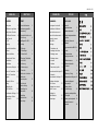
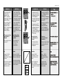
Sommaire
Consignes de sécurité 3
Conditions d’utilisation 3
Fonction de secours et
sens de fonctionnement 4
Types de vannes
pour AMV.... 4
Montage 5
- Orientations de
montage autorisées 5
- Montage vanne 6
- Montage moteur
et vanne 7
- Isolation 9
- Dimensions / poids 9
Branchement électrique 10
Schéma de
branchement électrique 11
Réglage mécanique
de la course 12
Réglage des contacts
fins de course 14
Réglage du
potentiomètre 16
Démontage 18
DEUTSCH
Inhalt
Sicherheitshinweise 3
Bestimmungsgemäße
Verwendung 3
Sicherheitsfunktion und
Wirkrichtung 4
Ventiltypen für AMV ... 4
Montage 5
- Zulässige
Einbaulagen 5
- Einbau Ventil 6
- Montage Stellantrieb
und Ventil 7
- Isolierung 9
- Abmessungen,
Gewichte 9
Elektrischer Anschluss 10
Elektrischer
Anschlussplan 11
Mechanische
Hubeinstellung 12
Einstellung der
Endschalter 14
Einstellung
Potentiometer 16
Demontage 18
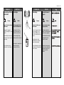
ENGLISH
Contents
Safety notes 3
Defifintion of application 3
Safety Return Function
and Effective Direction. 4
Valve Types for
AMV 41. 4
Mounting 5
Permissible Installation
Positions 5
- Valve Installation 6
- Actuator and Valve
Installation 7
- Insultation 9
- Dimensions, Weights 9
Electrical Connection 10
Electrical Connection
Diagram 11
Mechanical Stroke
Setting 12
- Adjusting the
End Switches 14
Potentiometer Settings 16
Dismounting of Valve
and Actuator 18
POLSKI
Spis treści
Warunki
bezpieczeństwa 3
Zakres zastosowań 3
Funkcja bezpieczeństwa
sprężyny
powrotnej i kierunek
działania 4
Typy zaworów do AMV41. 4
Montaż 5
- Dopuszczalne
pozycje montażu5
- Montaż zaworu 6
- Montaż siłownika
i zaworu 7
- Izolacja 9
- Wymiary / Wagi 9
Podłączenie elektryczne 10
Schemat podłączeń
elektrycznych 11
Nastawy skoku
mechanicznego 12
Regulacja przełączników
krańcowych 14
Nastawy potencjometru 16
Demontaż zaworu i
siłownika 18

3
AMV 410, 413
DEUTSCH
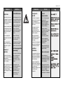
Sicherheitshinweise
Um Verletzungen an Perso-
nen und Schäden am Gerät
zu vermeiden, diese Anlei-
tung unbedingt beachten.
Montage, Inbetriebnahme
und Wartungsarbeiten
dürfen nur von sach-
kundigen und autorisierten
Personen durchgeführt
werden.
Anlage vor Montage,
Demontage unbedingt
drucklos machen.
Die Vorgaben des Anlagen-
herstellers und Anlagen-
betreibers sind zu beachten.
Bestimmungsgemäße
Verwendung
Der elektrische Stellantrieb
wird in Verbindung mit
folgenden Ventilen
eingesetzt: VFG 2(21),
VFG 25, VFU 2, VFGS 2,
AFQM 6
Einsatzgebiete sind
Temperaturregelung von
Wasser, Wasser-
Glykolgemischen und
Dampf für Heizungs-,
Fernheizungs- und
Kühlungsanlagen.
ENGLISH
Safety Notes
To avoid injury of persons
and damage to the device, it
is absolutely necessary to
carefully read and observe
these Instructions.
Necessary assembly, start-
up, and maintenance work
may be performed only by
qualified and authorized
personnel.
Prior to assembly and
disassembly, depressurize
system!
Please comply with the
instructions of the system
manufacturer or system
operator.
Definition of
application
The electrical actuator is
used in connection with the
following valves:
VFG 2(21), VFG 25, VFU 2,
VFGS 2, AFQM 6.
Fields of application are the
temperature control of
water, water-glycol mixtures
and steam for heating,
district heating and cooling
systems.
FRANCAIS
Consignes de
sécurité
Pour éviter les risques de
blessure pour les personnes
et les dommages sur
l’appareil, lire attentivement
cette notice.
Le montage, la mise en
route et les travaux
d’entretien doivent être
effectués par du personnel
qualifié et autorisé.
Mettre impérativement
l’installation hors pression
avant tout montage ou
démontage.
Respecter les consignes du
fabricant de l’installation et
de l’exploitant de celle-ci.
Conditions
d’utilisation
Le servomoteur électrique
est utilisé en combinaison
avec les vannes suivantes :
VFG 2(21), VFG 25, VFU 2,
VFGS2, AFQM6
Domaines d’application :
régulation de la température
de l’eau, de l’eau glycolée et
de la vapeur pour
chauffage, chauffage urbain
et installations de
réfrigération.
POLSKI
Warunki
bezpieczeństwa
W celu uniknięcia ryzyka
zranienia osób i
uszkodzenia urządzeń
należy bezwzględnie i
wnikliwie zapoznać się z
niniejszą instrukcją.
Niezbędny montaż,
uruchomienie oraz obsługa
mogą być dokonywane
wyłącznie przez
wykwalifikowany i
autoryzowany personel.
Należy bezwzględnie
zrzucić ciśnienie z układu
przed montażem i
demontażem.
Prosimy stosować się do
instrukcji producenta i/lub
operatora układu.
Zakres zastosowań
Siłownik elektryczny
stosowany jest w połączeniu
z następującymi zaworami:
VFG 2(21), VFG 25, VFU 2,
VFGS 2, AFQM 6
Znajdują zastosowanie w
regulacji temperatury wody,
roztworu woda-glikol i pary
wodnej w układach
grzewczych, instalacjach
sieci cieplnych i chłodzenia.

4
AMV 410, 413
DEUTSCH
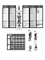
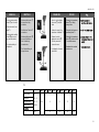
Sicherheitsfunktion
und Wirkrichtung
siehe Tabelle T1
Ventiltypen für
AMV 41.
Der elektrische Stellantrieb
AMV 41. kann auf folgende
Ventile montiert werden,
siehe Tabelle T2
ENGLISH
Safety Return
Function and
Effective Direction
see table T1
Valve Types for
AMV 41.
The electrical actuator AMV
41. can be mounted on the
following valves, see table
T2.
FRANCAIS
Fonction de secours
et sens de
fonctionnement
Voir tableau 1
Types de vannes
pour AMV 41.
Le moteur électrique AMV
41. peut être monté sur les
vannes suivantes, voir
tableau 2
POLSKI
Funkcja
bezpieczeństwa
sprężyny powrotnej i
kierunek działania
patrz Tabela T1
Typy zaworów do
AMV 41.
Siłownik elektryczny typu
AMV 41. może
współpracować z zaworami
regulacyjnymi, zgodnie z
Tabelą T2.
➀
T1 AME 410 413
VFU 2
VFG ..
VFGS 2
AFQM 6
-+
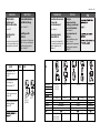
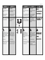
Safety function and
effective direction of
stem ➀
Sicherheitsfunktion und
Wirkrichtung der
Antriebsstange ➀
Fonction de secours et
sens de fonctionnement
de la tige ➀
Funkcja bezpieczeństwa
i kierunek działania
trzpienia ➀
➀
T2
Valve type VFG 2 VFU 2 VFGS 2 AFQM6
Ventiltyp VFG 21
Typ de vanne VFG 25
Typ zaworu
DN 15-80 15-80 15-80 15-80 40, 50
PN 16, 25, 40 25
Medium Hot water Steam Hotwater
Medium Heisswasser Dampf Heisswasser
Fluide Eau chaude Vapeur Eau chaude
Tmax Medium VFG 2: 200 150 200 350 150
VFG 25:200
VFG 21:150

5
AMV 410, 413
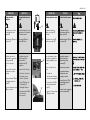
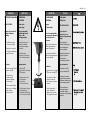
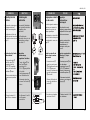
DEUTSCH
Montage
Zulässige Einbaulagen
DN 15 - 80
Mediumstemperaturen
bis 120 °C:
DN 15 - 80
Mediumstemperaturen
größer 120 °C:
Für Ventile VFGS 2
Dampf
ENGLISH
Mounting
Permissible Installation
Positions
DN 15 - 80
medium temperatures
to 120 °C:
DN 15 - 80
medium temperatures
> 120 °C:
For valves VFGS 2
steam
POLSKI
Montaż
Dopuszczalne pozycje
montażu
DN 15 – 80
Temperatura czynnika
do 120
0
C:
DN 15 – 80
temperatura czynnika
> 120
o
C:
Dla zaworów VFGS 2 para
wodna
VFG 2 (21), (25)
VFU 2
AFQM 6
VFU 2
AFQM 6
VFG 2 (21), (25)
VFGS 2
FRANCAIS
Montage
Orientations de montage
autorisées
DN 15 - 80
Température du fluide
jusqu’à 120°C :
DN 15 - 80
Température du fluide
supérieure à 120°C :
Pour vannes VFGS2 Vapeur

6
AMV 410, 413
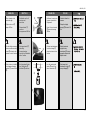
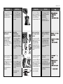
DEUTSCH
Einbau Ventil
1. Schmutzfänger vor dem
Ventil einbauen
2. Anlage vor dem Einbau
des Ventils spülen
3. Durchflussrichtung ➀ auf
dem Ventilgehäuse
beachten
Flansche ➁ in der Rohr-
leitung müssen parallel,
Dichtflächen sauber und
ohne Beschädigung sein.
4. Ventil einbauen
5. Schrauben über Kreuz
in 3 Stufen bis zum max.
Drehmoment anziehen
➀
➁
FRANCAIS
Montage vanne
1. Monter le filtre devant la
vanne
2. Rincer l’installation avant
le montage de la vanne
3. Respecter le sens
d’écoulement ➀ indiqué
sur le corps de la vanne
Les brides ➁ dans la
tuyauterie doivent être
parallèles, les surfaces
d’étanchéité propres et sans
dommages.
4. Monter la vanne
5. Serrer les vis en 3 étapes
en croix, jusqu’au couple
de rotation max.
POLSKI
Montaż zaworu
1. Zamontować filtr przed
zaworem.
2. Przed zamontowaniem
zaworu przepłukać
instalację.
3. Zwrócić uwagę na
wskaźnik kierunku
przepływu ➀ na korpusie
zaworu.
Kołnierze ➁ na rurociągu
muszą być wzajemnie
równoległe, a powierzchnie
pod uszczelki czyste i bez
uszkodzeń.
4. Zamontować zawór.
5. Dokręcać przeciwległe
nakrętki w 3 krokach do
osiągnięcia
maksymalnego momentu.
ENGLISH
Valve Installation
1. Install strainer in front of
valve.
2. Rinse system before
installing valve.
3. Observe flow direction ➀
on the valve body.
Flanges ➁ in the pipeline
system must be in parallel
direction, the sealing
surfaces must be clean and
undamaged.
4. Install valve.
5. Tighten screws crosswise
in 3 steps up to the
maximum torque.

7
AMV 410, 413
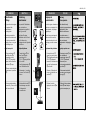
DEUTSCH
Montage Stellantrieb und
Ventil
Der Stellantrieb darf nur mit
eingefahrener Schubstange
➀ montiert werden.
Hubanzeige ➁ muss in
Position ➁ stehen
Bei Auslieferung ist die
Schubstange mittels
eingeschraubter
Montagechraube ➃
eingefahren.
Ist das nicht der Fall, dann :
1. elektrischen Anschluss
durchführen, siehe
nächsten Abschnitt
2. Taster ➂ drücken und
Schubstange ➀
vollständig einfahren
3. Montageschraube ➃ bis
zum Anschlag
einschrauben
ENGLISH
Actuator and Valve
Installation
The actuator must only be
mounted with the stem
retracted ➀.
Stroke indicator ➁ must be
in position ➁.
On delivery the stem is
retracted with a screwed-in
mounting screw ➃.
If this is not the case,
then:
1. carry out the electrical
connection, see next
section,
2. press pushbutton
➂ and
completely retract the
stem
➀ .
3. Screw in mounting screw
➃ up to its stop
FRANCAIS
Montage moteur et vanne
Uniquement monter le
moteur avec la tige ➀
rétractée
L’indication de course ➁
doit être en position ➁
Lors de la livraison, la tige
est rétractée à l’aide de la
vis de montage ➃ qui est
vissée
Si cela n’est pas les cas,
alors :
1. Procéder au
branchement électrique,
voir prochain paragraphe
2. Presser la touche ➂ et
rétracter totalement la
tige ➀
3. Visser la vis de montage
➃ jusqu’en butée
➂
➀
➁
➃
POLSKI
Montaż siłownika i zaworu
Aby siłownik mógł być
zamontowany musi mieć
cofnięty trzpień ➀.
Wskaźnik położenia ➁ musi
być w pozycji ➁.
W przypadku dostawy
trzpień jest cofnięty i
zaplombowany śrubą
montażową ➃.
W przeciwnym wypadku:
1. wykonać połączenie
elektryczne, patrz
następny rozdział
2. naciśnij przycisk ➂ do
całkowitego cofnięcia
trzpienia ➀
3. wkręcić śrubę montażową
aż do zatrzymania ➃

8
AMV 410, 413
DEUTSCH
3. Stellantrieb am Ventil
ansetzen und
ausrichten
4. Überwurfmutter ➀
anziehen
Anzugsmoment 100 Nm
5. Montageschraube ➁
unbedingt
herausschrauben,
sonst ist der Stellantrieb
außer Funktion
6. Bei hängendem Einbau
des Stellantriebs ➂
Aufkleber ➃ entfernen
ENGLISH
3. Place actuator on the
valve and align.
4. Tighten union nut ➀
torque 100 Nm
5. It is absolutely necessary
to unscrew the mounting
screw ➁, otherwise, the
actuator is out of function.
6. If the actuator is installed
in a downward hanging
position ➂, remove label
➃.
FRANCAIS
3. Positionner le moteur sur
la vanne et procéder à
l’alignement
4. Serrer l’écrou prisonnier
➀, facteur de serrage
100 Nm
5. Dévisser impérativement
la vis de montage ➁,
sinon le moteur est hors
fonction
6. Lors d’un montage du
moteur ➂ vers le bas,
retirer l’autocollant ➃
POLSKI
3. Umieścić siłownik na
zaworze
4. Dokręcić nakrętkę
łączącą ➀. Moment 100
Nm
5. Należy koniecznie
wykręcić śrubę
montażową ➁ w innym
przypadku siłownik nie
będzie działał.
6. Kiedy napęd jest
skierowany do dołu ➂
usunąć nalepkę ➃
➀
46 mm
➂
➁
3 mm
➃

9
AMV 410, 413
DEUTSCH
Isolierung
➀ zulässig
➁ unzulässig
Abmessungen, Gewichte
Flansche Anschlussmaße
nach DIN 2501, Dichtleiste
Form C
ENGLISH
Insulation
➀ acceptable
➁ intolerable
Dimensions, Weights
Flanges: connection
dimensions acc. to
DIN 2501, seal form C
FRANCAIS
Isolation
➀ Autorisé
➁ Non autorisé
Dimensions, poids
Dimensions raccordement à
brides selon DIN 2501,
étanchéité forme C
POLSKI
Izolacja
➀ do przyjęcia
➁ nie do przyjęcia
Rozmiar, Waga
Kołnierze – wymiary
połączeń zgodne z DIN
2501, uszczelka typu C.
➀
➁
VFU 2VFG(S).. DN 15 - 125
B
L
AMV(E) 413
B
L
C
235
14 5
285
14 5
125
AMV(E) 410
DN 15 20 25 32 40 50 65 80
VFG.. L mm 130 250 260 280 200 230 290 310
VFU 2
VFG 2 B 212 212 238 238 240 240 275 275
VFG21
VFG 25 kg 7 9 10 13 17 22 33 41
VFGS 2
VFU 2 B mm 95 95 106 106 123 123 135 135
C 311 311 337 337 339 339 374 374
kg 7 9 10 13 17 22 33 41

10
AMV 410, 413
DEUTSCH
Elektrischer
Anschluss
Gefahr durch
Stromschlag!
Bei unsachgemäßer
Handhabung besteht
Lebens- oder
Verletzungsgefahr.
Vor dem Anschluss der
Leitungen unbedingt
Spannungsversorgung
abschalten.
Durchführung des
elektrischen Anschlusses
nur durch Elektrofachkraft.
Vorgehensweise
1. Hutmutter ➀
abschrauben und Haube
➁ abnehmen
2. Leitungen nach dem
Anschlussplan
anschließen,
siehe nächste Seite
3. Vor Montage der Haube,
Einstellungen am
Stellantrieb durchführen,
siehe nächsten Abschnitt
➀
➁
ENGLISH
Electrical Connection
HIGH VOLTAGE !
Danger of injury and life
in case of improper
handling.
Switch off power supply
prior to connecting lines.
The electrical connection
must only be performed by
an expert electrician.
Procedure
1. Unscrew cap nut ➀ and
remove cover ➁.
2. Connect lines in
accordance with
connection diagram,
see next page.
3. Prior to remounting the
cover, carry out settings
at the actuator,
see next section.
FRANCAIS
Branchement
électrique
Danger
d’électrocution !
Lors d’une manipulation
non appropriée, danger de
mort ou risques de
blessures
Avant le branchement des
câbles, impérativement
couper l’alimentation.
Le branchement doit être
effectué uniquement par du
personnel qualifié.
Procédure :
1. Dévisser l’écrou du capot
➀ et retirer le capot ➁
2. Raccorder les câbles
selon le schéma de
branchement, voir page
suivante
3. Avant de remettre le
capot, effectuer les
réglages sur le moteur,
voir paragraphe suivant
POLSKI
Podłączenie
elektryczne
WYSOKIE NAPIĘCIE !
Ryzyko obrażeń i
zagrożenie życia w
przypadku nieprawidłowej
obsługi.
Przed wykonaniem
podłączeń elektrycznych
należy bezwzględnie
wyłączyć zasilanie.
Podłączenia elektryczne
mogą być wykonane
wyłącznie przez
uprawnionego elektryka.
Tryb postępowania
1. Odkręcić śrubę ➀ i
usunąć obudowę
➁.
2. Podłączyć przewody
zgodnie ze schematem
podłączeń elektrycznych -
patrz następna strona.
3. Przed założeniem
obudowy wykonać
wszystkie nastawy
siłownika - patrz następny
rozdział.

11
AMV 410, 413
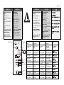
DEUTSCH
Elektrischer
Anschlussplan
➀ Anschluss für:
STB - Sicherheits-
temperaturbegrenzer
STW - Sicherheits-
temperaturwächter
SDB- Sicherheits-
druckbegrenzer
bei Anschluss unbedingt
Brücke entfernen
nur Typen AMV 413
mit Sicherheitsfunktion
ENGLISH
Electrical Connection
Diagram
➀ Connection for:
STB - Safety Temperature
Limiter
STW - Safety Temperature
Monitor
SDB - Safety Pressure
Limiter
Prior to connection, it is
absolutely necessary to
remove the jumper
only types AMV 413
with safety return function.
FRANCAIS
Schéma de branchement
électrique
➀ Branchement pour :
STB – Limiteur de
température de sécurité
STW – Contrôleur de
température de sécurité
SDB – Limiteur de pression
de sécurité
Lors du branchement,
impérativement retirer le
pont
Uniquement types AMV
413 avec fonction de
secours
POLSKI
Schemat podłączeń
elektrycznych
➀ Zaciski do:
STB – Ogranicznik
temperatury
bezpieczeństwa
STW – Strażnik temperatury
bezpieczeństwa
SDB – Ogranicznik ciśnienia
bezpieczeństwa
Przed połączeniem należy
koniecznie usunąć
mostek.
dot. wyłącznie typów AMV
413 z funkcją sprężyny
powrotnej.
1
11 12 13 14 15 16 20 21 22
PE
L R
1 2
1 2
44
S1 S2
End switches
CV
C
M
2
34
789
10
N
L
Pot
5 k
W
max. 1W
1 2 3
17 18
manual
➀
AMV 413
25 VAC
Power Spannungs Alimentation Napięcie
supply versorgung zasilania
3-position step 3punkt Schritt- Régulateur 3 Regulacja
controller Regler points sygnałem 3
– punktowym
Open valve Ventil Öffnen Ouvrir la vanne Zawór otwarty
(close VFU2) (VFU2 Schliessen) (VFU 2 fermée) (VFU 2 zamknięty
Close valve Ventil Schliessen Fermée la vanne Zawór zamknięty
(Open VFU2) (VFU2 öffnen) (Ouvrir VFU2) (VFU 2 otwarty)
Valve open Ventil auf Vanne ouverte Zawór otwarty
(VFU2 closed) (VFU2 zu) (VFU2 fermée) (VFU 2 zamknięty)
End switsches Endschalter Contacts fin Przełączniki
de course krańcowe
Valve closed Ventil zu Vanne fermée Zawór zamknięty
(VFU2 opened) (VFU2 auf) (VFU2 ouverte) (VFU 2 otwarty)
Pot Potentiometer Potentiometer Potencjometr
Valve open Ventil auf Vanne ouverte Zawór otwarty
(VFU2 closed) (VFU2 zu) (VFU2 fermée) (VFU2 zamknięty)
Stroke Hub Course Skok
Valve closed Ventil zu Vanne fermée Zawór zamknięty
(VFU2 opened) (VFU2 auf) (VFU2 ouverte) (VFU 2 otwarty)

12
AMV 410, 413
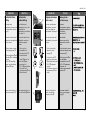
DEUTSCH
Mechanische
Hubeinstellung
Bei Ausführung mit
Potentiometer, zuerst die
Einstellung des
Potentiometers durchführen,
siehe Seite 16
Der Hub des elektrischen
Stellantriebs muss dem
Ventilhub angepasst
werden.
1. Falls noch nicht
durchgeführt, die
Montageschraube ➀
herausschrauben
2. Taster ➁ drücken bis
das Ventil ➂ ganz
geschlossen ist
(VFU 2 ➃ ganz geöffnet
ist) und die Lauf-
richtungsanzeige ➄ zum
Stillstand kommt
Hubanzeige beachten, sie
muss bis Position ➅ fahren
ENGLISH
Mechanical Stroke
Setting
For designs with
potentiometer, first carry out
the settings for the pot, see
page 16.
The stroke of the electrical
actuator must be adjusted to
the valve stroke.
1. If not yet done, unscrew
the mounting screw ➀.
2. Press pushbutton ➁ until
the valve ➂ is completely
closed
(VFU 2 ➃ completely
open) and the direction
indicator ➄ stops.
Observe stroke indicator, it
must move to position ➅.
FRANCAIS
Réglage mécanique
de la course
Pour une exécution avec
potentiomètre, procéder
d’abord au réglage du
potentiomètre, voir page 16
La course du moteur doit
être adaptée à la course de
la vanne
1. Si cela n’est pas fait,
dévisser la vis de
montage ➀
2. Presser la touche ➁
jusqu’à ce que la vanne
➂ soit totalement fermée
(VFU2 ➃ totalement
ouverte),
et l’indicateur de sens de
fonctionnement ➄ soit
arrêté
Observer l’indication de
course, elle doit aller
jusqu’en position ➅
POLSKI
Nastawy skoku
mechanicznego
Dla wersji z
potencjometrem, najpierw
przeprowadzić nastawy dla
potencjometru
Patrz strona 16.
Skok siłownika
elektrycznego musi być
przystosowany do skoku
zaworu.
1. Jeżeli nie jest to jeszcze
zrobione, odkręcić śrubę
montażową ➀.
2. Wcisnąć przycisk ➁ aż
do całkowitego
zamknięcia zaworu ➂
(VFU 2 ➃ całkowitego
otwarcia) i do
zatrzymania wskaźnika
poziomu ➄
Obserwować wskaźnik
poziomu, musi osiągnąć
pozycję ➅.
➁
➀
3 mm
➂
➃ VFU 2
➅
➄

13
AMV 410, 413
DEUTSCH
3. Hubeinstellschraube ➆
bis zum Anschlag
eindrehen
4. Ventilhub aus Tabelle T1
entnehmen
5. Hubeinstellschraube ➇
pro mm Ventilhub um
eine Umdrehung
herausdrehen
➻ Die Hubeinstellung ist
abgeschlossen
ENGLISH
3. Screw in stroke setting
screw ➆ up to its stop.
4. Take valve stroke from
table T1.
5. Unscrew stroke setting
screw ➇ by one turn
per mm valve stroke.
➻ The stroke setting is
completed.
FRANCAIS
3. Serrer la vis de réglage
de course ➆ jusqu’en
butée
4. Relever la course de la
vanne dans le tableau T1
5. Dévisser la vis de
réglage de course ➇
d’un tour par mm de
course de vanne
➻ Le réglage de la course
est terminé
POLSKI
3. Dokręcić śrubę nastawy
skoku ➆, aż do jej
zatrzymania.
4. Odczytać skok zaworu z
poniższej tabeli T1
5. Odkręcić śrubę nastawy
skoku ➇ jeden obrót na
1 mm skoku zaworu.
➻ Nastawa skoku została
zakończona.
➇
➆
➻
T1
DN 15 20 25 32 40 50 65 80
Valve stroke VFG 2
Ventilhub VFG 21
Course vanne VFG 25 mm 6 8 12 18
Skok zaworu AFQM 6
VFU2 8 10 14 20

14
AMV 410, 413
DEUTSCH
Einstellung der
Endschalter
Nur spezielle Stellantriebs-
typen sind mit Endschaltern
ausgeführt, siehe
Typenschild.
Die Einstellung der
Endschalter muss nach der
Hubeinstellung erfolgen,
siehe Seite 12
Endschalter
“Antriebsstange
ausgefahren” einstellen
1. Taster drücken ➁ bis
das Ventil ➂ ganz
geschlossen ist
(VFU 2 ➃ ganz geöffnet
ist) und die
Laufrichtungsanzeige ➄
zum Stillstand kommt
Hubanzeige beachten,
sie muss bis Position ➅
fahren
2. An Klemmen 14 und 16
ein Ohmmeter
anschließen
ENGLISH
Adjusting the End
Switches
Only special actuator types
are equipped with end
switches, see rating plate.
The adjustment of the end
switches must be done after
the stroke has been set, see
page 12.
Adjusting the End Switch
“Stem extended”
1. Press pushbutton ➁
until the valve ➂ is
completely closed
(VFU 2 ➃ completely
open) and the direction
indicator ➄ stops.
Observe stroke indicator,
it must move to position
➅.
2. Connect terminals 14
and 16 to an ohmmeter.
FRANCAIS
Réglage des contacts
fíns de course
Seuls des types de moteurs
spéciaux sont équipés de
contacts fins course, voir
plaque signalétique
Le réglage des contacts fins
de course doit se faire après
le réglage de la course, voir
page 12
Régler le contact fin de
course «tige du moteur
descendue»
1. Presser la touche ➁
jusqu’à ce que la vanne
➂ soit totalement fermée
(VFU2 ➃ totalement
ouverte) et l’indicateur de
sens de fonctionnement
➄ soit arrêté
Observer l’indication de
course, elle doit aller en
position ➅
2. Raccorder un ohmmètre
aux bornes 14 et 16
POLSKI
Regulacja
przełączników
krańcowych.
Tylko siłowniki w wersji
specjalnej są wyposażone w
przełączniki krańcowe, patrz
tabliczka znamionowa.
Regulacja przełączników
krańcowych może być
przeprowadzona po
nastawieniu skoku, patrz
strona 12.
Regulacja przełączników
krańcowych „ Trzpień
wysunięty”
1. Nacisnąć przycisk
➁ aż
do całkowitego
zamknięcia zaworu ➂
(VFU 2 ➃ całkowicie
otwarty) i zatrzymania
wskaźnika poziomu ➄.
Obserwować wskaźnik
poziomu, musi osiągnąć
pozycję ➅
2. Podłączyć zaciski 14 i 16
do omomierza.
➁
➂
➃ VFU 2
➅
➄
11 12 13 14 15 16
1 2
1 2
44
S1 S2
End switches
Ω

15
AMV 410, 413
DEUTSCH
3. Schraube ➀ drehen, bis
der Schaltnocken ➁ den
Endschalter ➂ schaltet
und das Ohmmeter 0 Ω
anzeigt
Endschalter
“Antriebsstange
eingefahren” einstellen
1. Taster drücken ➃ bis
das Ventil ➄ ganz
geöffnet ist ( VFU 2 ➅
ganz geschlossen ist)
und die Laufrichtungs-
anzeige ➆ zum Stillstand
kommt
2. An Klemmen 11 und 13
ein Ohmmeter
anschließen
3. Schraube ➇ drehen, bis
der Schaltnocken ➈ den
Endschalter ➉ schaltet
und das Ohmmeter 0 Ω
anzeigt
➻ Endschalter sind
eingestellt
ENGLISH
3. Turn screw ➀ until the
cam ➁ switches the end
switch ➂ and the
ohmmeter shows 0 Ω.
Adjusting the End Switch
“Stem retracted”
1. Press pushbutton ➃
until the valve ➄ is
completely open
(VFU 2 ➅ completely
closed) and the direction
indicator ➆ stops.
2. Connect terminals 11 and
13 to an ohmmeter.
3. Turn screw ➇ until the
cam ➈ switches the end
switch ➉ and the
ohmmeter shows 0 Ω.
➻ The end switches are
adjusted.
FRANCAIS
3. Tourner la vis ➀ jusqu’à
ce que le commutateur
➁ commute le contact fin
de course ➂ et que
l’ohmmètre indique 0 Ω
Régler le contact fin de
course «tige du moteur
rétractée»
1. Presser la touche ➃
jusqu’à ce que la vanne
➄ soit totalement
ouverte (VFU 2 ➅
totalement fermée) et
l’indicateur de sens de
fonctionnement ➆ soit
arrêté
2. Raccorder un ohmmètre
aux bornes 11 et 13
3. Tourner la vis ➇ jusqu’à
ce que le commutateur
➈ commute le contact fin
de course ➉ et que
l’ohmmètre indique 0 Ω
➻ Les contacts fins de
course sont réglés
POLSKI
4. Przekręcać śrubę ➀ aż
krzywka ➁ spowoduje
przełączenie
przełączników
krańcowych ➂, a
omomierz wskaże 0 Ω.
Regulacja przełączników
krańcowych „ Cofnięty
trzpień”
1. Nacisnąć przycisk ➃ do
całkowitego otwarcia
zaworu ➄ (VFU 2 ➅
całkowicie zamknięty) i
zatrzymania wskaźnika
poziomu ➆ .
2. Połącz zacisk 11 i 13 do
omomierza.
3. Przekręcać śrubę ➇ aż
krzywka ➈ rozłączy
przełącznik krańcowy ➉,
a omomierz wskaże 0 Ω
➻ Przełączniki krańcowe są
nastawione.
➆
➃
11 12 13 14 15 16
1 2
1 2
44
S1 S2
End switches
Ω
➀
➄ VFG..,
➅ VFU 2
➈
➇
➉
➻
13

16
AMV 410, 413
DEUTSCH
Einstellung
Potentiometer
Nur spezielle Stellantriebs-
typen sind mit dem
Potentiometer ausgeführt,
siehe Typenschild.
Nach jeder Montage
Stellantrieb und Ventil und
nach Entfernen der
Montageschraube folgendes
durchführen:
Nullpunkt justieren
1. Taster drücken ➀ bis
das Ventil ➁ ganz
geschlossen ist
(VFU 2 ➂ ganz geöffnet
ist) und die
Laufrichtungsanzeige ➃
zum Stillstand kommt
Hubanzeige beachten,
sie muss bis Position ➄
fahren
2. Hubeinstellschraube ➅ 2
Umdrehungen aus dem
Muttergewinde
herausdrehen
ENGLISH
Potentiometer
Settings
Only special actuator types
are equipped with
potentiometers,
see rating plate.
After having mounted a
valve and an actuator and
after having removed the
mounting screw, carry out
the following steps:
Adjust zero point
1. Press pushbutton ➀
until the valve ➁ is
completely closed
(VFU 2 ➂ completely
open) and the direction
indicator ➃ stops.
Observe stroke indicator,
it must move to position
➄.
2. Unscrew stroke setting
screw Å by 2 turns out of
the female thread.
FRANCAIS
Réglage du
potentiomètre
Seuls des types de moteurs
spéciaux sont équipés d’un
potentiomètre, voir plaque
signalétique
Après chaque montage du
moteur et de la vanne et
après avoir retirer la vis de
montage, procéder comme
suit
Ajustement du point zéro
1. Presser la touche ➀
jusqu’à ce que la vanne
➁ soit totalement fermée
(VFU2 ➂ totalement
ouverte) et l’indicateur de
sens de fonctionnement
➃ soit arrêté
Observer l’indication de
course, elle doit aller en
position ➄
2. Dévisser la vis de
réglage de course ➅ de
2 tours
POLSKI
Nastawy
potencjometra
Tylko siłowniki wersji
specjalnej są wyposażone w
potencjometry, patrz
tabliczka znamionowa.
Po montażu zaworu i
siłownika oraz usunięciu
śruby montażowej
przeprowadzić następujące
kroki:
Regulacja punktu zero.
1. Nacisnąć przycisk ➀ aż
do całkowitego
zamknięcia zaworu ➁
(VFU 2 ➂ całkowite
otwarcie) oraz
zatrzymania wskaźnika
poziomu ➃.
Obserwować wskaźnik
poziomu musi osiągnąć
pozycję ➄.
2. Odkręcić śrubę nastawy
skoku ➅ dwa obroty w
gwincie wewnętrznym.
➀
➁
➂ VFU 2
➄
➃
➅

17
AMV 410, 413
DEUTSCH
3. Taster drücken ➀ bis
das Ventil ganz geöffnet
ist (VFU 2 ganz
geschlossen ist) und die
Laufrichtungs-anzeige ➁
zum Stillstand kommt
4. Taster drücken ➂ bis
das Ventil ganz
geschlossen ist (VFU 2
ganz geöffnet ist) und
die Laufrichtungs-
anzeige ➁ zum Stillstand
kommt
➻➻
➻➻
➻ der Nullpunkt des
Potentiometers ist
justiiert
5. Anschließend die
Hubeinstellung
durchführen,
siehe Seite 12
Hinweis
Der Bereich 0- 5000 Ω
entspricht dem Maximalhub
(20 mm) des Stellantriebs.
Nach der Hubeinstellung
muss der Widerstandswert
entsprechend dem Ventilhub
gemessen werden.
ENGLISH
3. Press pushbutton ➀
until the valve is
completely open
(VFU 2 completely
closed) and the direction
indicator ➁ stops.
4. Press pushbutton ➂
until the valve ➁ is
completely closed
(VFU 2 completely open)
and the direction
indicator ➁ stops.
➻➻
➻➻
➻ The zero point of the
potentiometer is
adjusted
5. Then, adjust the stroke,
see page 12
Note
The range 0- 5000 Ω
corresponds to the
maximum stroke (20 mm) of
the actuator.
After the stroke is adjusted,
the resistance must be
measured in accordance
with the valve stroke.
FRANCAIS
3. Presser la touche ➀
jusqu’ŕ ce que la vanne
soit totalement ouverte
(VFU2 totalement
fermée) et l’indicateur de
sens de fonctionnement
➁ soit arręté
4. Presser la touche ➂
jusqu’ŕ ce que la vanne
soit totalement fermée
(VFU2 totalement
ouverte) et l’indicateur de
sens de fonctionnement
➁ soit arręté
➻➻
➻➻
➻ Le point zéro du
potentiomčtre est
ajusté
5. Ensuite procéder au
réglage de la course ,
voir page 12
Indication
La plage 0-5000 Ω
correspond à la course
maximum (20 mm) du
moteur.
Après le réglage de la
course, la valeur de
résistance doit être mesurée
en fonction de la course de
la vanne.
POLSKI
3. Nacisnąć przycisk ➀ aż
do całkowitego otwarcia
zaworu (VFU 2
całkowitego zamknięcia) i
zatrzymania wskaźnika
poziomu ➁.
4. Nacisnąć przycisk ➂ aż
do całkowitego
zamknięcia zaworu ‚
(VFU 2 całkowitego
otwarcia) i zatrzymania
wskaźnika poziomu ➁.
➻➻
➻➻
➻ Punkt zero
potencjometra jest
nastawiony
5. Następnie przeprowadzić
regulację skoku, patrz
strona 12. „
Uwaga
Zakres 0 – 5000 Ω
odpowiada skokowi
maksymalnemu (20mm)
siłownika.
Po regulacji skoku
rezystancja musi być
mierzona zgodnie ze
skokiem zaworu.
➀
➁
➂
0
20 mm
0
5000 Ω
Stroke
Hub
Course
Skok
➻➻
➻➻
➻

18
AMV 410, 413
POLSKI
Demontaż zaworu,
napędu
Uwaga
Ryzyko poparzenia parą
lub gorącą wodą!
Zawór bez napędu jest
otwarty ➀, uszczelnienie ➁
znajduje się w napędzie.
Przed demontażem należy
bezwzględnie zrzucić
ciśnienie z układu.
Kolejność wykonywanych
czynności przy demontażu
odwrotna w stosunku do
kolejności podczas
montażu.
FRANCAIS
Démontage
Danger
Risques de brûlures par
l’eau chaude
La vanne n’est pas étanche
sans moteur ➀, le cône
d’étanchéité ➁ se trouve
dans l’écrou de fixation du
moteur.
Impérativement mettre
l’installation hors pression
avant tout démontage.
Pour le démontage suivre la
procédure de montage dans
le sens inverse.
ENGLISH
Dismounting of Valve
and Actuator
Danger
Danger of injury by steam
or hot water!
Valve without actuator is
open ➀, sealing ➁ is in the
actuator.
It is absolutely necessary to
depressurize system prior to
dismounting.
Carry out dismounting in
reverse order as mounting.
DEUTSCH
Demontage
Gefahr
Verletzungsgefahr durch
Dampf oder Heißwasser
Ventil ist ohne Antrieb
offen ➀, Abdichtung ➁
befindet sich im Antrieb.
Vor Demontage Anlage
unbedingt drucklos machen.
Demontage in umgekehr-ter
Reihenfolge wie die
Montage durchführen.
➁
➀
-
 1
1
-
 2
2
-
 3
3
-
 4
4
-
 5
5
-
 6
6
-
 7
7
-
 8
8
-
 9
9
-
 10
10
-
 11
11
-
 12
12
-
 13
13
-
 14
14
-
 15
15
-
 16
16
-
 17
17
-
 18
18


w innych językach
- Deutsch: Danfoss AMV 410/413 Bedienungsanleitung
- français: Danfoss AMV 410/413 Mode d'emploi
- English: Danfoss AMV 410/413 Operating instructions
Powiązane artykuły
-
Danfoss AMV 410, 413 Instrukcja obsługi
-
-
-
-
-
-
-
-
-