Tesla Air to Water Heat Pump-TGTP-14HMDA1 Instrukcja obsługi
- Kategoria
- Klimatyzatory typu split
- Typ
- Instrukcja obsługi
Niniejsza instrukcja jest również odpowiednia dla

HEATPUMP AIR-TO-WATER
(HYDRO MODULE)
USER
MANUAL
Ver. 2022
SRBENG

OPERATING INSTRUCTION
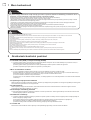
Note: All the pictures in this manual are just schematic diagrams, the actual is the standard. Please read
this owner’s manual carefully and thoroughly before operating the unit! Take care of this manual for future
reference.
ENG
UPUTSTVO ZA UPOTREBU
Napomena: Sve slike u ovom priručniku su samo šematski dijagrami, fizički proizvod je standard. Molimo
Vas da pažljivo i temeljno pročitate ovo uputstvo za upotrebu pre korišćenja uređaja! Sačuvajte ovo
uputstvo za buduću upotrebu.
SRB

3
ENG
Applicable Model:
8KW
12KW
16KW
Dear user:
Thank you for using our products!
This manual is a universal version of our hydronic module for air to
water heat pump unit. Although the appearance of the hydronic module
you purchased may not match the appearance described in this manual, it
will not affect your operation and use.
Please read carefully before use and keep this manual in a safe place
for your use.
You are using our hydronic module for air to water heat pump unit,
which requires regular cleaning and maintenance. If your module
is not properly cleaned and maintained, its failure rate will increase and its
service life will be greatly reduced. .
In order to protect your legal rights, please install it by a professional.
You are using our module for . If it
is not used for a long time in winter, please ensure that the machine is
powered on 24 hours a day. Make sure to drain the water from the system
to avoid freezing the system.
hydronic
hydronic air to water heat pump unit

4
ENG
Applicable Model:
8KW
12KW
16KW
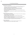
1. The appliance shall be installed in accordance with national wiring
regulations.
2. This appliance is intended to be used by expert or trained users in
shops, in light industry and on farms, or for commercial use by lay
persons.
3. This appliance is not intended for use by persons (including children)
with reduced physical, sensory or mental capabilities, or lack of
experience and knowledge, unless they have been given supervision or
instruction concerning use of the appliance by a person responsible for
their safety.
4. Children should be supervised to ensure that they do not play with the
appliance.
5. This appliance can be used by children aged from 8 years or above and
persons with reduced physical, sensory or mental capabilities or lack of
experience and knowledge if they have been given supervision or
instruction concerning use of the appliance in a safe way and understand
the hazards involved.
6. Cleaning and user maintenance shall not be made by children without
supervision.
7. Disconnect the power source before service or replacing parts.
8. Warning: before obtaining access to terminals, all supply circuits must
be disconnected.
Warning
!

5
ENG
Applicable Model:
8KW
12KW
16KW
9. Disconnect the power supply before cleaning and maintenance.
10. If the supply cord is damaged, it must be replaced by the manufacturer,
its service agent or a similarly qualified person in order to avoid a hazard.
11. An all-pole disconnection switch having a contact separation of at least
3mm in all poles should be connected in fixed wiring.
12. The appliance shall not be installed in the laundry.
13. F-gas ,The equipment contains fluorinated greenhouse gas
R32,Global Warming Potential(GWP):677
Warning
!
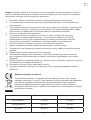
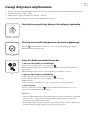
Correct Disposal of this product
This marking indicates that this product should not be disposed
with other household wastes throughout the EU. To prevent
possible harm to the environment or human health from
uncontrolled waste disposal, recycle it responsibly to promote
the sustainable reuse of material resources. To return your used
device, please use the return and collection systems or contact
the retailer where the product was purchased. They can take this
product for environmental safe recycling.
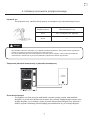
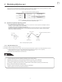
outdoor temperature indoor temperature
cooling mode operation -5~46℃-25~40℃
heating mode operation -28~43℃-25~40℃
DHW mode operation -28~43℃-25~40℃

6
ENG
111
25
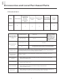
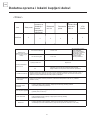
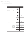
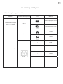
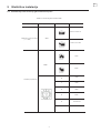
Accessories and Local Purchased Parts
<Accessories>
Name Wall Panel
Installation
Manual&
Energy
efficiency
label
Warranty
Card
Y-Type
Filter
Quantity
Copper tube (GB1527-
2006 Drawn tube of
copper and copper
alloys)
Rigid polyethylene
plastic pipe
Insulation case
Automatic water
supply valve
Water distributor &
collector
Floor heating pipe
Room thermostat
Buffer tank
Liquid-side piping Φ9.52×0.8
Φ16×0.8
Gas-side piping
For the connection of
the refrigerant system
between the outdoor
unit and the hydronic
module, it is
recommended to use
the soft copper tube
(TP2M), the length of
which is selected
according to your actual
demand.
Outer diameter mm Remarks
The drain pipe is used to connect the hydronlic module.
Its length is selected according to your actual demand.
The thickness of the insulation case for refrigerant-side pipeline is usually more than 15 mm,
and that of insulation case for the water-side pipeline more than 20 mm. For the pipeline in
the enclosed wet area, the case shall be properly thickened.
Purchase according to your actual demand, (maximum water temperature: 80 °C, set
pressure: 1.5 bar)
When installing floor heating, purchase according to actual demand (requiring the
automatic flow adjustment)
When installing floor heating, purchase according to actual demand
(diameter φ20, PE-RT tube)
When installing floor heating, purchase according to actual demand
(requiring linkage control)
When installing floor heating, purchase according to actual demand (the tank does not
provide domestic hot water, the recommended tank volume: 100~200L)
Replacement
Board
1
Extended
Wire &DHW
Tank Sensor
1 1

7
ENG
!
!
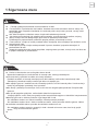
-1-
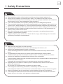
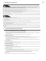
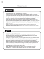
1 Safety Precautions
Warning
The installation position of the hydronic module must be protected against rain .
Please entrust a dealer or professional to install. The installer must have relevant
professional knowledge. Do not install by yourself, the improper installation will cause fire,
electric shock, injury, water leakage and other accidents.
If you need to purchase in local place, please purchase our designated products.
If you purchase the products which are not designated by our company, it may result in fire,
electric shock, water leakage, etc. The retail products shall be installed by a professional.
Observe the regulations of the local electrical regulations when making power connections.
According to the law, reliable grounding work must be carried out. If the grounding is not
perfect, it may cause electric shock.
When the heat pump or water heater needs to be moved or reinstalled, please let the
supplier or professional to operate.
Improper repairing may result in fire, electric shock, injury, water leakage, etc. It must be
repaired by the supplier or professional.
Attention
Make sure the drain pipe can drain smoothly.
Improper pipe installation may result in water leakage, wet furniture, etc.
Check if the leakage protection switch is installed.
The earth leakage protection switch must be installed, otherwise it may cause electric
shock.
It is prohibited to install the unit in a place where flammable gas is easily leaked.
If the flammable gas leaks and traps around the indoor unit, it may cause fire accident.
Confirm the installation foundation and hoisting is firm and reliable.
If the foundation and hoisting are not strong enough, it may cause accident of falling objects.
Connect the cable correctly.
If the cable is connected incorrectly, it may damage the electrical components.
Exposing the unit to water or moisture prior to installation may cause short circuits in
electrical components.
Do not store it in a wet basement or expose it to rain or water.
If the refrigerant leaks during installation, immediately ventilate the room.
If the refrigerant leaks out and comes into contact with the fire, it may produce toxic gases.
After the installation work is completed, confirm that the refrigerant is not leaking.
If the refrigerant leaks into the room and comes into contact with a fire source, such as a
heater, stove or rice cooker, toxic gases may be generated.

8
ENG
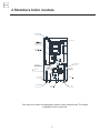
-2-
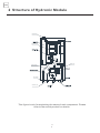
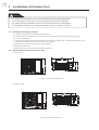
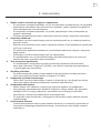
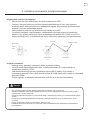
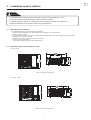
2 Structure of Hydronic Module
This figure is only for explaining the name of each component. Please
refer to the actual product for details.
Air purge Valve
Wired controller
liquid-side pipe
Expansion vessel
Gas-side pipe
Safety valve

9
ENG
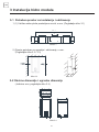
-3-
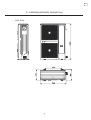
>1000
>500
>300
74
80
50
421.2
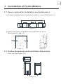
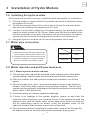
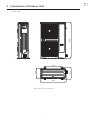
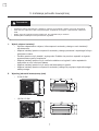
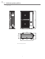
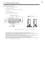
3 Installation of Hydro Module
3-1 Space required for installation and maintenance
1) The size of the wall panel mounted on the wall, in mm.(See Figure 3.1)
Figure 3.1
2) Space required for installation and maintenance, in mm.
(See Figure 3.2 and 3.3)
Figure 3.2 Figure 3.3
3-2 Outline dimensions and installation dimensions
(Unit: mm, see Figure 3.4)
Figure 3.4

10
ENG
-4-
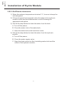
3 Installation of Hydro Module
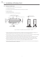
3.3 Handling
1) To avoid damage during shipping, please do not open the carton until
installation.
2) The hydronic module is heavy and requires at least two people to handle.
3) When handling the unit, please take the protective measures.
4) When handling the unit, please take protective measures for the surface of
the unit to prevent damage to the unit panel.
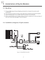
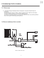
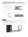
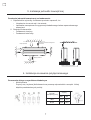
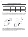
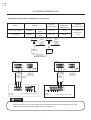
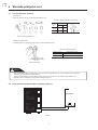
3.4 Installation diagram of hydro module
Figure 3.5 DHW Mode operation
Fan coil unit
(Cooling/Heating)
Radiator unit
(Heating)
Floor heating loop
(Heating)
Filter
T7
Water inlet
Water outlet
Filter
Motorized 3-way valve
(SV4 status:ON)
Buffer tank
Expension
vessel
DHW tank
Differential pressure
water supply valve
Circulating Pump
Filter
Differential pressure
water supply valve
hot water
cool water
Motorized 2-way valve
(SV3 status:OFF)

11
ENG
-5-
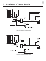
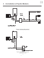
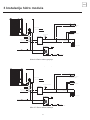
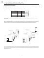
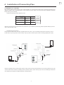
3 Installation of Hydro Module
Figure 3.6 Heating Mode operation
Figure 3.7 Cooling Mode operation
Fan coil unit
(Cooling/Heating)
Radiator unit
(Heating)
Floor heating loop
(Heating)
Filter
T7
Water inlet
Water outlet
Filter
Buffer tank
Expension
vessel
DHW tank
Differential pressure
water supply valve
Circulating Pump Motorized 2-way valve
(SV3 status:OFF)
Filter
Differential pressure
water supply valve
Outdoor Unit (14、16kW)
hot water
cool water
Motorized 3-way valve
(SV4 status:OFF)
Fan coil unit
(Cooling/Heating)
Radiator unit
(Heating)
Floor heating loop
(Heating)
Filter
T7
Water inlet
Water outlet
Filter
Buffer tank
Expension
vessel
DHW tank
Differential pressure
water supply valve
Circulating Pump
Filter
Differential pressure
water supply valve
Outdoor Unit (14、16kW)
hot water
cool water
Motorized 3-way valve
(SV4 status:OFF)
Motoized 2-way valve
(SV3 status:ON)

12
ENG
-6-
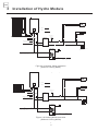
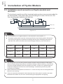
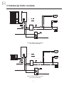
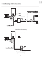
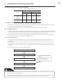
3 Installation of Hydro Module
Figure 3.8 Heating Mode operation
(Without Cooling Mode)
Figure 3.9 Heating Mode operation
(Without Cooling Mode)
Fan coil unit
(Heating)
Radiator unit
(Heating)
Floor heating loop
(Heating)
Filter
T7
Water inlet
Water outlet
Filter
Motorized 3-way valve
(SV4 status:OFF)
Buffer tank
Expension
vessel
DHW tank
Differential pressure
water supply valve
Circulating Pump
Filter
Differential pressure
water supply valve
Outdoor Unit (14、16kW)
hot water
cool water
Fan coil unit
(Heating)
Radiator unit
(Heating)
Floor heating loop
(Heating)
Filter
T7
Water inlet
Water outlet
Filter
Buffer tank
Expension
vessel
DHW tank
Differential pressure
water supply valve
Circulating Pump
Filter
Differential pressure
water supply valve
Outdoor Unit (10、12kW)
hot water
cool water
Motorized 3-way valve
(SV4 status:OFF)

13
ENG
-7-
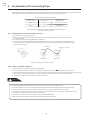
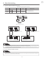
3 Installation of Hydro Module
Figure 3.8 Heating Mode operation
(Without DHW Mode&DHW Tank)
Figure 3.9 DHW Mode operation
(DHW Mode only)
Fan coil unit
(Cooling/Heating)
Radiator unit
(Heating)
Floor heating loop
(Heating)
Water inlet
Water outlet
Filter
Buffer tank
Expension
vessel
Differential pressure
water supply valve
Circulating Pump
Filter
Outdoor Unit (5、8kW)
Motorized 2-way valve
(SV3 status:ON)
hot water
cool water
Water inlet
Water outlet
Filter
Differential pressure
water supply valve
Filter
Outdoor Unit (5、8kW)
hot water
cool water
DHW tank
Differential pressure
water supply valve
Filter
Differential pressure
water supply valve
Filter
T7

14
ENG
!
6.5-8.0 200 V/cmμ<50ppm <50ppm
<50ppm <30ppm <0.3ppm <50ppm
-
-
-8-
!
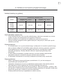
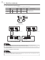
3 Installation of Hydro Module
3.5 Installation and connection of hydro module and
terminal
The hydronic module and the terminal water system are recommended to
be connected in the same way (the following is a case of a fan coil, the
floor heating and radiator are similar)
Fan coil Fan coil Fan coil
Water inlet
Water outlet
Figure 3.8
Warning
The temperature of supplied water in the tank shall not exceed 50 °C.
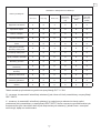
The water quality shall meet the values specified in the following table. Otherwise ,
the scaling will appear in the heat exchanger and the floor heating system after a
period of use, which will affect the heat exchange efficiency and cause failure.
Ph value Total hardness Conductivity Sulfide ion Chloride Ammonia ion
N/A N/A
Sulfate ion Silicon Iron content Sodium ion Calcium ion
No request
Warning
The refrigerant circuit of the hydronic module contains a small amount of Nitrogen,
which is used to keep the pressure and detect leakage. When installing, unscrew the
nut of the refrigerant pipe joint of the hydronic module. If there is no gas flowing out,
check the refrigerant circuit of the unit for leakage. Install and operate only after
confirming no leakage.
When the ambient temperature is below 0°C, be sure to keep the unit energized when
the unit is not running.
If the unit cannot be energized, drain the water from the hydronic module, the water
tank and each water line, so as to avoid freezing the equipment and piping.

15
ENG
!
DN32
-9-
DN32
3 Installation of Hydro Module
3.6 Installing the hydro module
As the hydronic module is heavy, it needs at least two people for installation.
1) Choose a wall or support that is fully reliable and safe to withstand twice
the weight of the unit.
2) Fix the mounting bracket of the unit on the wall with 8 expansion bolts.
(the minium mounting hole diameter is 8.5 mm)
3) In order to ensure the reliability of the load-bearing, the wall drilling hole
needs to reach a depth of 45~50 mm. Make sure that the brackets on the
wall are installed horizontally. Otherwise, the air in the water circulation
system will not be easily discharged and cause the unit malfunction.
4) Hang the hydronic module on the mounting bracket on the wall.
3.7 Water pipe connection
Attention
When connecting the water pipeline, be
sure to tighten them with two wrenches.
Please check if the exhaust valve in the
hydronic module can normally release
the air in the water circulation system.
Water pipe
specification
Outlet pipe
Inlet pipe
3.8 Water injection and antifreeze measures
3.8.1 Water injection and air exhaust
1) The exhaust valve should be installed at the highest point of the water
system piping, and the drain valve should be set at the lowest point.
2) After the outdoor unit and hydronic module are installed, turn off the
power.
3) Open the water inlet valve, unscrew the exhaust valve on the hydronic
module, and fill the water system of the hydronic module. The air in the
system can be gradually discharged through the exhaust valve and the
water outlet of the water tank.
4) Check the water circulation system for leakage.
5) If there is no leakage in the system pipeline, power on and start the
machine. After the pump runs, exhaust the air in the system through the
exhaust valve and the water outlet of the water tank. After the sound of
the air exhausting cannot be heard, close the exhaust valve on the
hydronic module and the water outlet valve of the tank.
6) For the system without installing the water tank, exhaust air through the
air exhaust valve on the hydronic module and water way system.

16
ENG
-10-
3 Installation of Hydro Module
3.8.2 Antifreeze measures
1) When the ambient temperature is below 0 °C, be sure to keep the
unit energized.
2) If the unit cannot be energized, drain the water in the hydronic
module, buffer tank and water wires to avoid freezing the
equipment and pipline.
3) Follow the steps below to drain the water from the tank.
A. Turn off the power;
B. Close the water inlet of the water tank;
C. Open the water tank outlet and drain valve;
4) Follow the steps below to drain the water from the hydronic
module.
A. Turn off the power;
B. Close the water supply valve;
C. Open the drain valves on the circulating water inlet and the
outlet of the hydronic module;

17
ENG
!
-11-
220-240V~50Hz
32
8KW
12KW
16KW
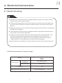
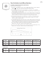
4 Electrical Connections
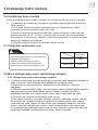
4.1 Electrical wiring
Attention
lThe hydronic module should use a dedicated power supply. The supply voltage
should conform to the rated voltage.
lThe external power supply circuit of the hydronic module must be grounded, and
the ground wire of hydronic module should be reliably connected to the external
ground.
lWiring construction must be carried out by a professional technician in accordance
with the circuit diagram.
lThe connected fixed line must be equipped with an all-pole disconnection device
with at least 3 mm contact separation.
The power wire and signal wire should be arranged neatly and reasonably, and
should not interfere with each other, and should not be in contact with the
connecting pipe and the valve body. it is not allowed to connect the two wires
unless the joint is firmly welded and covered with insulating tape.
lAfter the wiring is completed, the power can be turned on after careful inspection
l
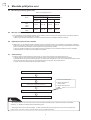
1) Detailed parameters of power supply
Model
Power supply
Voltage and
frequency
2
Power wire (mm )
Fuse (A)
2
Weak electrical signal wire (mm )
3-core×4.0
3-core shielded cable 3×0.75

18
ENG
-12-
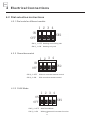
4 Electrical Connections
SW2
4321
OFF
ON
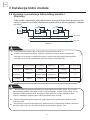
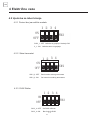
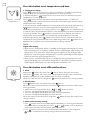
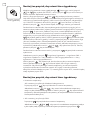
4.2.3 DHW Mode
SW2
4321
OFF
ON
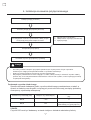
4.2 Dial selection instructions
4.2.1 Dial code for different models
SW 2_1: OFF Heating and cooling unit
SW 2_1: ON Heating only unit
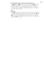
4.2.2 Room thermostat
SW 2_2 :OFF Without room thermostat control
SW 2_2 :ON With room thermostat control
SW 2_4 :OFF With DHW Mode
SW 2_4 :ON Without domestic hot water function
SW2
4321
OFF
ON

19
ENG
-13-
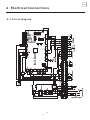
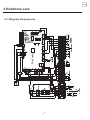
4 Electrical Connections
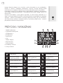
L1 N1
IC 5674312
321
54312
4321
12 12
~
LN
321
4.3 Circuit diagram

20
ENG
-15-
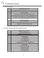
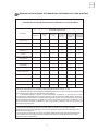
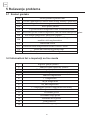
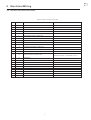
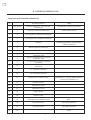
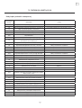
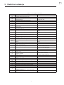
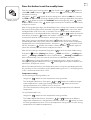
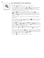
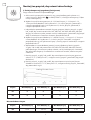
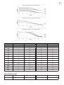
E0 Water flow switch fault
E1 Communication fault between hydronic module and outdoor
E2 T1 fault of outlet water temperature sensor
E5 Outdoor unit fault
E6 T7 fault of DHW tank water temperature sensor
E7 Tw_in fault of heat exchanger inlet water temperature sensor
E8 Tw_out fault of heat exchanger outlet water temperature
E9 Communication fault between hydronic module
and wired controller
P0 EEPROM protection
P1 Protection for large temperature difference of inlet and outlet
P2 Protection for insufficient water flow
P3 T1 and Tw_out simultaneous fault protection
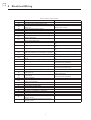
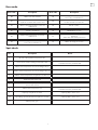
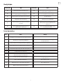
1Capacity of outdoor unit
2Set mode of indoor unit
3Operating mode of outdoor unit
4Operating capacity demand for indoor unit
5Set temperature
6T1 temperature
7Tw_in temperature
8Tw_out temperature
9T7 temperature(DHW Tank Temperature)
10 T4 ambient temperature
11 Previousfault
12 Previous second fault
13 Previous third fault
14 Software version
15 Pump output level
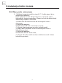
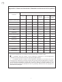
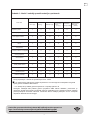
5 Troubleshooting
5.1 Fault codes
5.2 Spot inspection information sheet
Strona się ładuje...
Strona się ładuje...
Strona się ładuje...
Strona się ładuje...
Strona się ładuje...
Strona się ładuje...
Strona się ładuje...
Strona się ładuje...
Strona się ładuje...
Strona się ładuje...
Strona się ładuje...
Strona się ładuje...
Strona się ładuje...
Strona się ładuje...
Strona się ładuje...
Strona się ładuje...
Strona się ładuje...
Strona się ładuje...
Strona się ładuje...
Strona się ładuje...
Strona się ładuje...
Strona się ładuje...
Strona się ładuje...
Strona się ładuje...
Strona się ładuje...
Strona się ładuje...
Strona się ładuje...
Strona się ładuje...
Strona się ładuje...
Strona się ładuje...
Strona się ładuje...
Strona się ładuje...
Strona się ładuje...
Strona się ładuje...
Strona się ładuje...
Strona się ładuje...
Strona się ładuje...
Strona się ładuje...
Strona się ładuje...
Strona się ładuje...
Strona się ładuje...
Strona się ładuje...
Strona się ładuje...
Strona się ładuje...
Strona się ładuje...
Strona się ładuje...
Strona się ładuje...
Strona się ładuje...
Strona się ładuje...
Strona się ładuje...
Strona się ładuje...
Strona się ładuje...
Strona się ładuje...
Strona się ładuje...
Strona się ładuje...
Strona się ładuje...
Strona się ładuje...
Strona się ładuje...
Strona się ładuje...
Strona się ładuje...
Strona się ładuje...
Strona się ładuje...
Strona się ładuje...
Strona się ładuje...
Strona się ładuje...
Strona się ładuje...
Strona się ładuje...
Strona się ładuje...
Strona się ładuje...
Strona się ładuje...
Strona się ładuje...
Strona się ładuje...
Strona się ładuje...
Strona się ładuje...
Strona się ładuje...
Strona się ładuje...
Strona się ładuje...
Strona się ładuje...
Strona się ładuje...
Strona się ładuje...
Strona się ładuje...
Strona się ładuje...
Strona się ładuje...
Strona się ładuje...
Strona się ładuje...
Strona się ładuje...
Strona się ładuje...
Strona się ładuje...
Strona się ładuje...
Strona się ładuje...
Strona się ładuje...
Strona się ładuje...
Strona się ładuje...
Strona się ładuje...
Strona się ładuje...
Strona się ładuje...
Strona się ładuje...
Strona się ładuje...
-
 1
1
-
 2
2
-
 3
3
-
 4
4
-
 5
5
-
 6
6
-
 7
7
-
 8
8
-
 9
9
-
 10
10
-
 11
11
-
 12
12
-
 13
13
-
 14
14
-
 15
15
-
 16
16
-
 17
17
-
 18
18
-
 19
19
-
 20
20
-
 21
21
-
 22
22
-
 23
23
-
 24
24
-
 25
25
-
 26
26
-
 27
27
-
 28
28
-
 29
29
-
 30
30
-
 31
31
-
 32
32
-
 33
33
-
 34
34
-
 35
35
-
 36
36
-
 37
37
-
 38
38
-
 39
39
-
 40
40
-
 41
41
-
 42
42
-
 43
43
-
 44
44
-
 45
45
-
 46
46
-
 47
47
-
 48
48
-
 49
49
-
 50
50
-
 51
51
-
 52
52
-
 53
53
-
 54
54
-
 55
55
-
 56
56
-
 57
57
-
 58
58
-
 59
59
-
 60
60
-
 61
61
-
 62
62
-
 63
63
-
 64
64
-
 65
65
-
 66
66
-
 67
67
-
 68
68
-
 69
69
-
 70
70
-
 71
71
-
 72
72
-
 73
73
-
 74
74
-
 75
75
-
 76
76
-
 77
77
-
 78
78
-
 79
79
-
 80
80
-
 81
81
-
 82
82
-
 83
83
-
 84
84
-
 85
85
-
 86
86
-
 87
87
-
 88
88
-
 89
89
-
 90
90
-
 91
91
-
 92
92
-
 93
93
-
 94
94
-
 95
95
-
 96
96
-
 97
97
-
 98
98
-
 99
99
-
 100
100
-
 101
101
-
 102
102
-
 103
103
-
 104
104
-
 105
105
-
 106
106
-
 107
107
-
 108
108
-
 109
109
-
 110
110
-
 111
111
-
 112
112
-
 113
113
-
 114
114
-
 115
115
-
 116
116
-
 117
117
-
 118
118


Tesla Air to Water Heat Pump-TGTP-14HMDA1 Instrukcja obsługi
- Kategoria
- Klimatyzatory typu split
- Typ
- Instrukcja obsługi
- Niniejsza instrukcja jest również odpowiednia dla
w innych językach
Inne dokumenty
-
 Kaisai KHX-16PY3 Instrukcja obsługi
-
Blaupunkt MBS0709E Instrukcja obsługi
-
Anslut Jula 416-086 Instrukcja obsługi
-
temperzone CTC-1 instrukcja
-
 Lyson W2022NZ Instrukcja obsługi
-
Carrier 30AWH006HB Instrukcja instalacji
-
Stanley ST-221A-240-E Instrukcja obsługi
-
WarmlyYours SCE-120 Economy Snow & Ice Melt Control Instrukcja instalacji
-
OJ ETO2 Instructions Manual
-
OJ Electronics ETO2-EU Instrukcja obsługi

