
ELECTRONICS FOR SPECIALISTS ELECTRONICS FOR SPECIALISTS ELECTRONICS FOR SPECIALISTS ELECTRONICS FOR SPECIALISTS
BEDIENUNGSANLEITUNG
INSTRUCTION MANUAL
MODE D’EMPLOI
ISTRUZIONI PER L’USO
GEBRUIKSAANWIJZING
MANUAL DE INSTRUCCIONES
INSTRUKCJA OBSŁUGI
SIKKERHEDSOPLYSNINGER
SÄKERHETSFÖRESKRIFTER
TURVALLISUUDESTA
TXS-1800
Bestell-Nr. • Order No. 25.5130
1,8 GHz
Empfänger
für ein Funkmikrofon
Receiver
for a Wireless Microphone

ELECTRONICS FOR SPECIALISTS ELECTRONICS FOR SPECIALISTS ELECTRONICS FOR SPECIALISTS ELECTRONICS FOR SPECIALISTS
2
Deutsch ..........Seite 4
English ...........Page 9
Français ..........Page 14
Italiano...........Pagina 20
Nederlands .......Pagina 25
Español ..........Página 30
Polski ............Strona 35
Dansk ............Sida 40
Svenska ..........Sidan 40
Suomi............Sivulta 41

3
DC INPUT
LINE OUT
(BAL.)
LINE OUT
(UNBAL.)
ANT. B ANT. A
POWER
TXS-1800
1
2
7 8 9
3 4 5 6
➀
➁
➂
DC INPUT
LINE OUT
(BAL.)
LINE OUT
(UNBAL.)
ANT. B ANT. A
12
mm
13
mm
➃

4
Deutsch
English
English Page
Français
Français Page
Italiano
Italiano Pagina
Español
Español Página
Nederlands
Nederlands Pagina
Polski
Polski Strona
Deutsch
Deutsch Seite
Empfänger für ein Funkmikrofon
Diese Bedienungsanleitung richtet sich an Benutzer
ohne besondere Fachkenntnisse. Bitte lesen Sie die
Anleitung vor dem Betrieb gründlich durch und
heben Sie sie für ein späteres Nachlesen auf.
Auf der ausklappbaren Seite3 finden Sie alle
beschriebenen Bedienelemente und Anschlüsse.
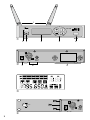
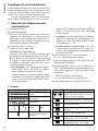
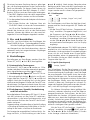
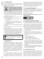
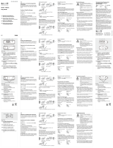
1 Übersicht der Bedienelemente
und Anschlüsse
1 Empfangsantennen
2 Infrarot-Sendediode
3 Taste ADL, um über ein Infrarot-Signal die Funk-
frequenz des Empfängers an den Sender zu
übertragen; am Empfänger durchgeführte Ein-
stellungen für den Sender (Sendeleistung und
Gain) werden ebenfalls übertragen
4 Display (
☞
Abb. 3 und Kap. 1.1)
5 Tasten SET, AUTO, und
Automatische Tastensperre:
Kurze Zeit nach dem Einschalten und nach der
letzten Bedienung werden die Tasten SET, AUTO,
und automatisch gesperrt (Sperrsymbol
im Display). Um die Sperre aufzuheben bzw. um
sie wieder zu aktivieren, die Taste SET für ca.
1Sekunde gedrückt halten.
1. Einstellmodus: Bei aufgehobener Tasten-
sperre lassen sich mit der Taste SET nachein-
ander folgende Funktionen aufrufen:
Gruppeneinstellung Kanaleinstellung Squelch-
Einstellung Einstellung der Sendeleistung für den
Sender Gain-Einstellung für den SenderVerlas-
sen des Einstellmodus
Solange die Anzeige der gewählten Funktion
blinkt, ist die Einstellung mit den Tasten
und möglich.
2. Lautstärke: Die Lautstärke für das Ausgangs-
signal des Empfängers bei aufgehobener Tas-
tensperre mit den Tasten und einstellen
(Einstellbereich 0 … 63).
3. Automatischer Kanalsuchlauf: Um den
Kanalsuchlauf innerhalb einer Gruppe zu
starten, bei aufgehobener Tastensperre die
Taste AUTO drücken.
6 Taste POWER zum Ein- und Ausschalten
(für ca. 1 Sekunde gedrückt halten)
7
Stromversorgungsbuchse zum Anschluss des
beiliegenden Netzgerätes
8
Audioausgänge, jeweils zum Anschluss an
einen Mikrofoneingang oder hochempfindli-
chen Line-Eingang z. B. eines Mischpults oder
Verstärkers
– XLR-Einbaustecker, symmetrisch
– 6,3-mm-Klinkenbuchse, asymmetrisch
9 Antenneneingänge A und B (BNC-Buchsen)
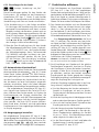
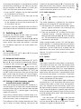
Anzeige Funktion
Empfangsstärke des Funk-
signals
Lautstärke des empfangenen
Audiosignals
Funkfrequenz
Gruppe Kanal
zeigt den Zustand der Batte-
rien im Sender in mehreren
Stufen an
Anzeige Funktion
das Empfangsteil (A oder B), welches das
stärkere Funksignal empfängt, wird durch
ein Antennensymbol angezeigt
Wellensymbol pulsiert bei IR-Übertragung
blinkt bei Kanalsuchlauf
Squelch (Rauschsperre), in 3 Stufen
einstellbar
Tasten SET, AUTO, , gesperrt
Einstellung für den Sender:
Sendeleistung, in 3 Stufen einstellbar
Einstellung für den Sender: Anpassung des
Lautstärkepegels (0 dB, –3 dB, –6 dB)
1.1 Display

5
Deutsch
2 Hinweise für den
sicherenGebrauch
Die Geräte (Empfänger und Netzgerät) entsprechen
allen relevanten Richtlinien der EU und tragen des-
halb das -Zeichen.
WARNUNG Das Netzgerät wird mit lebensge-
fährlicher Netzspannung versorgt.
Nehmen Sie deshalb niemals selbst
Eingriffe daran vor. Es besteht die
Gefahr eines elektrischen Schlags.
•
Setzen Sie die Geräte nur im Innenbereich ein.
Schützen Sie sie vor Tropf- und Spritzwasser
sowie hoher Luftfeuchtigkeit. Der zulässige Ein-
satztemperaturbereich beträgt 0 – 40 °C.
•
Ziehen Sie sofort das Netzgerät aus der Steckdose,
1. wenn sichtbare Schäden am Empfänger oder
am Netzgerät vorhanden sind,
2. wenn nach einem Sturz oder Ähnlichem der
Verdacht auf einen Defekt besteht,
3. wenn Funktionsstörungen auftreten.
Lassen Sie die Geräte in jedem Fall in einer Fach-
werkstatt reparieren.
•
Verwenden Sie zum Reinigen nur ein trockenes,
weiches Tuch, niemals Wasser oder Chemikalien.
•
Werden die Geräte zweckentfremdet, nicht richtig
angeschlossen, falsch bedient oder nicht fachge-
recht repariert, kann keine Haftung für daraus re-
sultierende Sach- oder Personenschäden und keine
Garantie für die Geräte übernommen werden.
Sollen die Geräte endgültig aus dem
Betrieb genommen werden, übergeben
Sie sie zur umweltgerechten Entsorgung
einem örtlichen Recyclingbetrieb.
3 Einsatzmöglichkeiten
Mit diesem Multifrequenz-Empfänger TXS-1800
und einem Sender der TXS-1800-Serie (Funkmikro-
fon TXS-1800HT oder Taschensender TXS-1800HSE)
lässt sich ein draht loses Audio-Übertragungs system
aufbauen, z. B. für Bühnen einsätze. Das Gerät ver-
wendet „True Diversity“-Technik: Das Sendesignal
wird von zwei Antennen empfangen und in zwei
separaten Empfangsteilen verstärkt. Das jeweils bes-
ser empfangene Signal wird dann weiterverarbeitet.
Das TXS-1800-System arbeitet im UHF-Bereich
1785 – 1800 MHz (16 Kanalgruppen mit jeweils
12 Kanälen). Besonders komfortabel ist die Fre-
quenzsynchronisation: Per Knopfdruck wird über
ein Infrarotsignal der Sender auf die am Empfänger
gewählte Funkfrequenz eingestellt. Sendeleistung
und Gain des Senders können am Empfänger ein-
gestellt werden, diese Daten werden ebenfalls bei
der IR-Übertragung dem Sender übermittelt.
3.1 Konformität und Zulassung
Hiermit erklärt MONACOR INTERNATIONAL, dass
der Empfänger TXS-1800 der Richtlinie 2014 / 53 / EU
entspricht. Die EU-Konformitätserklärung ist im
Internet verfügbar:
www.img-stageline.de
Es bestehen Beschränkungen oder Anforde-
rungen in folgenden Ländern:
CZ UK
4 Aufstellung und Anschluss
Für optimalen Empfang sollte der Empfänger min.
1 m über dem Boden, nicht zu nah an angrenzen-
den Wänden, platziert werden. Zwischen Sender
und Empfänger sollte Sichtverbindung bestehen
und sie sollten nicht in unmittelbarer Nähe zu
Metallflächen oder digitalen Geräten (wie z. B.
CD-Spieler, Computer) positioniert werden.
1)
Die mitgelieferten Empfangsantennen (1) an die
Antennenbuchsen (9) anschließen und V-förmig
nach oben ausrichten.
2)
Für den Anschluss an einen Mikrofoneingang
oder an einen hochempfindlichen Line-Eingang
des nachfolgenden Geräts (z. B. Mischpult, Ver-
stärker) einen der beiden Audioausgänge (8)
verwenden:
– symmetrisch beschalteter XLR-Ausgang
(phantomspannungsfest),
– asymmetrisch beschalteter 6,3-mm-Klinken-
ausgang; passendes Anschlusskabel liegt bei
Bei großer Distanz zwischen den Geräten sollte
der XLR-Ausgang bevorzugt werden. Die sym-
metrische Signalführung bietet einen besseren
Schutz gegen Störeinstrahlungen, die besonders
bei längeren Kabeln auftreten können.
3)
Zur Stromversorgung das beiliegende Netzgerät
an die Stromversorgungsbuchse (7) anschließen
und in eine Netzsteckdose (230 V/ 50 Hz) stecken.
4.1 Rack-Montage
Für den Einbau in ein Rack (482 mm / 19”) liegen
zwei Rackwinkel bei. Zuerst an jeder Seite des Emp-
fängers die vordere Schraube entfernen. Es sind
dann auf jeder Seite drei Löcher für die Befestigung
des Rackwinkels vorhanden. Dann die Rackwinkel
mit den beiliegenden Schrauben an den Seiten des
Empfängers festschrauben (
☞
Abb. 4).

6
Deutsch
Für einen besseren Empfang kann es günstiger
sein, die Empfangsantennen an der Frontseite des
Racks zu platzieren. Zu diesem Zweck lassen sich
die Antennen auch über BNC-Adapter (2 × BNC-
Buchse, 50 Ω) an je einem Rackwinkel anbringen:
1)
Den BNC-Adapter durch das dafür vorgesehene
Loch des Winkels stecken und festschrauben.
2)
An die vordere Buchse des Adapters die Antenne
anschließen.
3)
Die hintere Buchse des Adapters über ein
50-Ω-BNC-Kabel mit einer der Antennenbuch-
sen (9) auf der Geräterückseite verbinden.
Werden die Antennen nicht an den Rackwinkeln
montiert, können die Löcher mit den zwei bei-
liegenden Kunststoffkappen abgedeckt werden.
5 Ein- und Ausschalten
Zum Ein- und Ausschalten des Empfängers die
Taste POWER (6) für ca. 1 Sekunde gedrückt halten.
Wird der Empfänger längere Zeit nicht benutzt,
sein Netzgerät aus der Steckdose ziehen, denn es
verbraucht auch bei ausgeschaltetem Empfänger
einen geringen Strom.
6 Einstellungen
Einstellungen am Empfänger werden über die
Tasten SET, AUTO, und (5) durchgeführt.
6.1 Automatische Tastensperre
Die Tasten SET, AUTO, und werden ca. 15Se-
kunden nach dem Einschalten automatisch gesperrt,
wenn keine Bedienung erfolgt ( im Display).
Zur Aufhebung der Sperre die Taste SET für ca.
1Sekunde gedrückt halten. erlischt und Einstel-
lungen über die Tasten SET, AUTO, und sind
möglich. Nach der Einstellung lässt sich die Sperre
durch erneutes längeres Drücken der Taste SET wie-
der aktivieren. Die Sperre wird auch kurze Zeit nach
der letzten Bedienung wieder automatisch aktiviert.
6.2 Funkfrequenz, Squelch, Sendeleistung
und Gain einstellen
Bei aufgehobener Tastensperre (
☞
Kap. 6.1) lassen
sich die Funktionen mit der Taste SET nacheinan-
der anwählen. Ist die letzte Funktion erreicht, wird
durch weiteres Drücken der Taste SET der Einstell-
modus verlassen:
Gruppeneinstellung Kanaleinstellung Squelch-Einstellung
Einstellung der Sendeleistung für den Sender Gain-Ein-
stellung für den Sender Verlassen des Einstellmodus
Die Anzeige der angewählten Funktion blinkt. So-
lange sie blinkt, ist die Einstellung mit den Tasten
und möglich. Nach einigen Sekunden ohne
Betätigung einer Taste wird der Einstellmodus au-
tomatisch verlassen, die durchgeführten Einstel-
lungen werden auch in diesem Fall gespeichert.
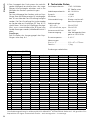
6.2.1 Funkfrequenz
GR CH
Anzeigen „Gruppe“ und „Kanal“
Die Funkfrequenz wird über die Wahl der Kanal-
gruppe und des Kanals eingestellt (
☞
Tabelle auf
Seite 8).
1)
Mit der Taste SET die Funktion „Gruppeneinstel-
lung“ anwählen (Gruppenanzeige blinkt) und
die Gruppe mit der Taste oder einstellen.
2) Danach mit der Taste SET die Funktion „Kanal-
einstellung“ anwählen (Kanalanzeige blinkt) und
mit der Taste oder den Kanal einstellen. Die
entsprechende Funkfrequenz wird im Display
angezeigt.
Bei Parallelbetrieb mehrerer TXS-1800-Funksysteme
empfiehlt es sich, Kanäle aus derselben Gruppe zu
verwenden. Unter optimalen Einsatzbedingungen
lassen sich bis zu 8 Kanäle einer Gruppe gleich-
zeitig betreiben, ohne sich gegenseitig zu stören.
Zur schnellen Suche von freien Kanälen in einer
Gruppe siehe Kap. 6.3.
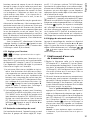
6.2.2 Squelch (Rauschsperre)
Anzeige „Squelch“
Der Schwellwert für die Rauschsperre ist in drei
Stufen einstellbar. Die Rauschsperre sorgt für eine
Stummschaltung des Empfängers, wenn der Pegel
des empfangenen Funksignals unter den einge-
stellten Schwellwert sinkt. So wird verhindert, dass
hochfrequente Störsignale zu einem Aufrauschen
des Empfängers führen, wenn der Sender ausge-
schaltet ist oder sein Funksignal zu schwach ist:
Liegen die Pegel der Störsignale unter dem Schwell-
wert, wird der Empfänger stummgeschaltet.
Ein höherer Schwellwert bietet größere Stör-
sicherheit, reduziert allerdings auch die Übertra-
gungsreichweite des Funksystems, da die Funk-
signalstärke des Senders im Betrieb ausreichend
hoch sein muss, damit der Empfänger nicht stumm-
schaltet. So kann bei gutem Empfang ein höherer
Schwellwert eingestellt werden, bei größerer Ent-
fernung zwischen Sender und Empfänger dagegen
sollte ein niedrigerer Wert gewählt werden.
Mit der Taste SET die Funktion „Squelch-Ein-
stellung“ anwählen (Anzeige blinkt) und mit
der Taste oder die Stufe einstellen (3 Stufen
in der Anzeige = höchster Schwellwert).

7
Deutsch
6.2.3 Einstellungen für den Sender
Anzeigen „Sendeleistung“ und „Gain“
Diese Einstellungen gelten für den Sender des
Funksystems. Sie werden bei der Frequenzsyn-
chronisation (
☞
Kap. 7, Punkt 2) zum Sender
übertragen. Es besteht aber auch die Möglichkeit,
Sendeleistung und Gain am Sender einzustellen.
1)
Die Sendeleistung ist in drei Stufen einstellbar.
Ein Verringern der Sendeleistung führt zu einem
geringeren Stromverbrauch und damit zu einer
längeren Laufzeit der Batterien, jedoch auch zu
einer kürzeren Übertragungsreichweite. Mit der
Taste SET die Funktion „Einstellung der Sendeleis-
tung“ anwählen (Anzeige blinkt) und mit der
Taste oder die Stufe einstellen (3Stufen in
der Anzeige = höchste Sendeleistung).
2) Über die Gain-Einstellung kann für den Sender
die Mikrofonempfindlichkeit (beim Funkmik-
rofon TXS-1800HT) bzw. die Empfindlichkeit
des Mikrofoneingangs (beim Taschensender
TXS-1800HSE) verringert und damit sein Laut-
stärkepegel korrigiert werden. Mit der Taste
SET die Funktion „Gain-Einstellung“ anwählen
(Anzeige blinkt) und mit der Taste oder
0 dB, −3 dB oder −6 dB einstellen.
6.3 Automatischer Kanalsuchlauf
Über den Kanalsuchlauf findet das Gerät innerhalb
der eingestellten Kanalgruppe (
☞
Kap. 6.2.1) einen
freien Kanal. Sollen mehrere TXS-1800-Funksys-
teme gleichzeitig am Einsatzort betrieben werden,
vor dem Durchführen des Kanalsuchlaufs die Sen-
der, die bereits auf eine Funkfrequenz eingestellt
wurden, einschalten, damit die schon belegten
Kanäle beim Kanalsuchlauf ausgeschlossen werden.
Bei aufgehobener Tastensperre (
☞
Kap.6.1)
zum Starten eines Suchlaufs die Taste AUTO drü-
cken. Während der Suche werden im Display die
Funkfrequenzen der Gruppe durchlaufen, die
Anzeige blinkt und die Ziffernsegmente der
Kanalanzeige rotieren. Soll der Suchlauf abgebro-
chen werden, die Taste AUTO erneut drücken.
Nach Ende eines Suchlaufs wird die gefundene
Funkfrequenz mit ihrer zugehörigen Kanalnummer
im Display angezeigt.
6.4 Ausgangspegel einstellen
Bei aufgehobener Tastensperre (
☞
Kap. 6.1) den
Ausgangspegel des Empfängers mit der Taste oder
einstellen. Der eingestellte Wert wird kurz im Dis-
play angezeigt ( … ), dann wechselt
das Display zurück auf Anzeige der Funkfrequenz.
7 Funkstrecke aufbauen
1)
Die Funkfrequenz am Empfänger einstellen
(
☞
Kap. 6.2.1, Kap. 6.3). Den zugehörigen
Sender noch ausgeschaltet lassen. Zeigt bei aus-
geschaltetem Sender die Balkenanzeige RF im Dis-
play (4) ein Signal an, werden Störungen oder Si-
gnale eines anderen Funksystems empfangen. In
diesem Fall eine andere Funkfrequenz einstellen.
2)
Den Sender einschalten und sein Batteriefach
öffnen, damit der Infrarot-Sensor nicht abge-
deckt ist. Den Infrarot-Sensor auf die Infra-
rot-Sendediode (2) des Empfängers ausrichten.
Es muss Sichtverbindung zwischen IR-Sensor und
IR-Sendediode bestehen (Abstand bis zu ca. 2 m).
Zur Frequenzsynchronisation die Taste
ADL (3) drücken: Der Sender wird per Infra-
rot-Signal auf die Funkfrequenz des Empfängers
eingestellt, die Sendeleistung und die Gain-Ein-
stellung (
☞
Kap. 6.2.3) werden ebenfalls zum
Sender übermittelt. Während der IR-Über tragung
pulsiert das Wellensymbol in der Anzeige . Die
erfolgreiche Übertragung wird am Sender durch
Aufleuchten des Displays angezeigt.
Hinweis: Funkfrequenz, Sendeleistung und Gain las-
sen sich auch manuell am Sender einstellen.
3)
Sind Empfänger und Sender auf die gleiche
Funkfrequenz eingestellt, leuchtet im Display
des Empfängers in einer der beiden Antennen-
anzeigen A oder B ein Antennensymbol auf
(je nachdem, welches der beiden separaten
Empfangsteile des Geräts gerade das stärkere
Funksignal empfängt) und die Balkenanzeige RF
zeigt den Empfang des Funksignals an.
Wird kein Empfang angezeigt oder ist der Emp-
fang schlecht, folgende Punkte überprüfen:
a) Sind die Batterien des Senders verbraucht?
Sowohl im Empfänger- als auch im Sender-
Display zeigt ein Batteriesymbol den Zustand
der Batterien an.
b) Wird der Empfang durch Metallgegenstände
oder andere Hochfrequenz-Quellen gestört?
c)
Lässt sich der Empfang durch Schwenken der
Empfangsantennen verbessern?
d)
Ist der Abstand zwischen Empfänger und Sen-
der zu groß? Die Reichweite ist von den ört-
lichen Gegebenheiten abhängig (im Freifeld
bis zu ca. 100 m). Die Übertragungsstrecke
sollte möglichst hindernisfrei sein.
e)
Ist die Rauschsperre zu hoch und /oder die
Sendeleistung zu niedrig eingestellt?
(
☞
Kapitel 6.2.2 bzw. 6.2.3)

8
Deutsch
4) Zum Auspegeln des Funksystems das nachfol-
gende Audiogerät einschalten bzw. den zuge-
hörigen Mischpultregler aufziehen und in das
Mikrofon des Senders sprechen / singen:
Sender
Der Lautstärkepegel des Senders wird am Emp-
fänger über die Balkenanzeige AF wiedergege-
ben. Er kann über die Gain-Einstellung korrigiert
werden. Die Gain-Einstellung lässt sich entweder
am Sender oder am Empfänger (
☞
Kap. 6.2.3)
durchführen. Wird sie am Empfänger durchge-
führt, muss sie anschließend per IR-Signal zum
Sender übertragen werden (siehe Bedienschritt2
oben).
Empfänger
Zum Einstellen des Ausgangspegels des Emp-
fängers siehe Kap. 6.4.
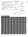
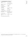
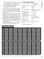
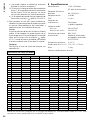
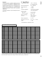
8 Technische Daten
Funkfrequenzbereich: . . . 1785 – 1800 MHz
☞
Tabelle unten
Audiofrequenzbereich: . . 60 – 16 000 Hz
Dynamik: . . . . . . . . . . . . > 95 dB
Klirrfaktor: . . . . . . . . . . . < 0,8 %
Störunterdrückung: . . . . . Pilotton und einstell-
bare Rauschsperre
Audioausgänge
XLR, sym.: . . . . . . . . . . 50 mV/ 150 Ω
6,3-mm-Klinke, asym.: 50 mV/1 kΩ
Antennenanschlüsse: . . . BNC, 50 Ω
Stromversorgung: . . . . . . über beiliegendes Netz-
gerät an 230 V/ 50 Hz
Einsatztemperatur: . . . . . 0 – 40 °C
Abmessungen
(B × H × T): . . . . . . . . . . . 212 × 47 × 175 mm
Gewicht: . . . . . . . . . . . . . 1,3 kg
Änderungen vorbehalten.
Diese Bedienungsanleitung ist urheberrechtlich für MONACOR
®
INTERNATIONAL GmbH & Co. KG geschützt. Eine
Reproduktion für eigene kommerzielle Zwecke – auch auszugsweise – ist untersagt.
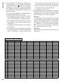
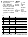
Funkfrequenzen (in MHz)
CH GR 1 GR 2 GR 3 GR 4 GR 5 GR 6 GR 7 GR 8
1 1795,650 1795,050 1785,500 1795,100 1795,100 1785,150 1799,850 1785,200
2 1796,050 1795,450 1785,950 1795,500 1795,950 1785,550 1799,450 1785,600
3 1796,750 1796,150 1786,850 1796,350 1797,250 1786,400 1798,600 1786,450
4 1797,250 1797,100 1787,250 1796,850 1797,700 1786,900 1798,100 1786,950
5 1797,650 1797,500 1788,100 1797,700 1798,650 1787,750 1797,250 1787,800
6 1799,000 1798,350 1788,650 1798,100 1799,100 1795,850 1795,850 1788,200
7 1799,400 1798,950 1789,500 1799,500 1785,100 1796,250 1795,450 1795,950
8 1785,700 1799,350 1789,950 1795,950 1785,500 1797,200 1793,950 1796,700
9 1786,100 1785,100 1790,550 1797,250 1786,350 1797,950 1793,550 1797,650
10 1786,950 1785,500 1791,000 1798,650 1786,850 1798,400 1792,650 1798,500
11 1787,450 1786,350 1791,900 1799,100 1788,100 1799,050 1792,200 1798,900
12 1788,300 1786,850 1793,150 1799,650 1789,100 1799,450 1790,750 1799,450
CH GR 9 GR 10 GR 11 GR 12 GR 13 GR 14 GR 15 GR 16
1 1799,800 1795,250 1785,150 1794,050 1795,350 1799,050 1785,500 1785,250
2 1799,400 1795,850 1785,800 1793,150 1795,750 1798,600 1786,050 1785,650
3 1798,550 1796,350 1786,250 1792,750 1796,900 1798,050 1786,500 1786,500
4 1798,050 1797,300 1786,800 1791,900 1797,300 1797,600 1787,400 1787,000
5 1797,200 1797,750 1787,250 1791,350 1798,150 1796,700 1787,850 1788,250
6 1795,800 1798,650 1788,100 1790,500 1798,650 1796,250 1788,550 1789,650
7 1795,400 1799,050 1788,600 1790,050 1799,500 1795,550 1788,950 1790,100
8 1794,350 1799,900 1790,050 1789,450 1799,900 1795,150 1795,900 1790,700
9 1793,500 1796,900 1790,500 1789,000 1796,350 1793,750 1796,750 1797,650
10 1793,000 1798,150 1791,900 1788,100 1797,750 1793,250 1797,150 1798,100
11 1792,150 1799,500 1792,750 1787,700 1799,050 1792,850 1798,050 1798,700
12 1791,750 1799,950 1793,150 1786,550 1799,450 1791,100 1798,500 1799,100

9
English
Italiano
Italiano Pagina
Español
Español Página
Nederlands
Nederlands Pagina
Receiver for a Wireless Microphone
These instructions are intended for users without
any specific technical knowledge. Please read these
instructions carefully prior to operation and keep
them for later reference.
All operating elements and connections de-
scribed can be found on the fold-out page 3.
1 Operating Elements
andConnections
1 Receiving antennas
2 IR transmitting diode
3 Button ADL, to transfer the radio frequency of
the receiver to the transmitter by IR signal; set-
tings for the transmitter (transmission power and
gain) made on the receiver will also be transferred
4 Display (
☞
fig. 3 and chapter 1.1)
5 Buttons SET, AUTO, and
Automatic lock function:
A short while after switching on and after the
last operation, the buttons SET, AUTO, and
will be locked automatically (lock symbol
on the display). To unlock the buttons or to lock
them again, keep the button SET pressed for
approx. 1 second.
1. Setting mode: When the buttons are un-
locked, use the button SET to call up the fol-
lowing functions one after another:
Group setting channel setting squelch setting
setting of transmission power for the transmitter
gain setting for the transmitter exit of setting mode
As long as the indication of the function se-
lected keeps flashing, settings can be made
with the buttons and .
2. Volume: When the buttons are unlocked, use
the buttons
and
to set the volume for the
output signal of the receiver (range 0 … 63).
3. Automatic channel scan: When the buttons
are unlocked, press the button AUTO to start
the channel scan within a group.
6
Button POWER to switch the receiver on / off
(keep button pressed for approx. 1 second)
7 Power supply jack to connect the power supply
unit provided
8
Audio outputs, one each for connection to a
microphone input or to a highly sensitive line
input (e. g. of a mixer or amplifier)
– XLR chassis plug, balanced
– 6.3 mm jack, unbalanced
9 Antenna inputs A and B (BNC jacks)
English
English Page
Indication Function
strength of the radio signal
received
volume of the audio signal
received
radio frequency
group channel
indicates the battery status
of the transmitter in several
levels
Indication Function
an antenna symbol will indicate the receiver
section (A or B) receiving the radio signal of
the highest quality
wave symbol will pulsate during IR trans-
mission
starts flashing during the channel scan
squelch, adjustable in 3 levels
buttons SET, AUTO, , locked
setting for the transmitter:
transmission power, adjustable in 3 levels
setting for the transmitter: matching of
volume level (0 dB, –3 dB, –6 dB)
1.1 Display

10
English
2 Safety Notes
The units (receiver and power supply unit) corre-
spond to all relevant directives of the EU and are
therefore marked with .
WARNING
The power supply unit uses danger-
ous mains voltage. Leave servicing
to skilled personnel only. Inexpert
handling may result in electric
shock.
•
The units are suitable for indoor use only. Pro-
tect them against dripping water, splash water
and high air humidity. The admissible ambient
temperature range is 0 – 40 °C.
•
Immediately disconnect the power supply unit
from the mains socket
1. if the receiver or the power supply unit is vis-
ibly damaged,
2. if a defect might have occurred after a unit
was dropped or suffered a similar accident,
3. if malfunctions occur.
In any case the units must be repaired by skilled
personnel.
•
For cleaning only use a dry, soft cloth; never use
water or chemicals.
•
No guarantee claims for the units and no liability
for any resulting personal damage or material
damage will be accepted if the units are used
for other purposes than originally intended, if
they are not correctly connected or operated, or
if they are not repaired in an expert way.
If the units are to be put out of operation
definitively, take them to a local recycling
plant for a disposal which is not harmful
to the environment.
3 Applications
Combined with a transmitter of the TXS-1800
series (wireless microphone TXS-1800HT or pocket
transmitter TXS-1800HSE), this multifrequency
receiver TXS-1800 can be used to set up a wireless
audio transmission system, e. g. for stage applica-
tions. The receiver uses “True Diversity” technol-
ogy: The signal sent is received by two antennas
and amplified in two separate receiver sections.
The signal of the highest reception quality is then
processed.
The TXS-1800 system operates in the UHF
range 1785 – 1800 MHz (16 channel groups of
12channels each). A most convenient feature is
the frequency synchronization: At the press of a
button the transmitter will be matched to the radio
frequency of the receiver by IR signal. Transmission
power and gain of the transmitter can be set on
the receiver; these data will also be transferred to
the transmitter during IR transmission.
3.1 Conformity and approval
Herewith, MONACOR INTERNATIONAL declare that
the receiver TXS-1800 complies with the directive
2014 / 53 / EU. The EU declaration of conformity is
available on the Internet:
www.img-stageline.com
Restrictions or requirements apply in the fol-
lowing countries:
CZ UK
4 Setting up and Connection
For optimum reception, place the receiver at least
1 m above the ground, not too close to adjacent
walls. Make sure that there are no obstacles be-
tween the transmitter and the receiver. Do not posi-
tion the units in the immediate vicinity of metal sur-
faces or digital devices (e. g. CD player, computer).
1) Connect the receiving antennas provided (1) to
the antenna jacks (9) and put them upright in a
V-shaped position.
2) For connection to a microphone input or to a
highly sensitive line input of the subsequent unit
(e. g. mixer, amplifier), use one of the two audio
outputs (8):
– balanced XLR output
(phantom power resistant)
– unbalanced 6.3 mm output jack;
matching connection cable is supplied
When the units are placed far apart, the XLR
output should be preferred. The balanced signal
transmission offers higher protection against
interference which may occur especially with
long cables.
3)
For power supply, connect the power supply unit
provided to the power supply jack (7) and to a
mains socket (230 V/ 50 Hz).
4.1 Installation into a rack
For installation into a rack (482 mm / 19”), two rack
brackets are supplied. First remove the front screw
on each side of the receiver. Now there are three
holes on each side for attaching the rack bracket.
Then use the screws supplied to fasten the rack
brackets to the sides of the receiver (
☞
fig. 4).

11
English
To improve the reception it may be better to place
the receiving antennas at the front of the rack.
For this purpose, use BNC adapters (2 × BNC jack,
50 Ω) to attach each antenna to a bracket:
1) Insert the BNC adapter into the hole provided
on the bracket and fasten it.
2)
Connect the antenna to the front jack of the
adapter.
3) Use a 50 Ω BNC cable to connect the rear jack
of the adapter to one of the antenna jacks (9)
on the rear of the unit.
Two plastic caps are supplied to cover the holes if
the antennas are not attached to the rack brackets.
5 Switching on / off
To switch the receiver on / off, keep the button
POWER (6) pressed for approx. 1 second.
If the receiver is not in use for a longer period
of time, disconnect the power supply unit from the
mains socket. Even when the receiver is switched
off, the power supply unit has a low power con-
sumption.
6 Settings
Use the buttons SET, AUTO, and (5) to make
settings on the receiver.
6.1 Automatic lock function
When no button is pressed, the buttons SET, AUTO,
and will be locked automatically approx.
15seconds after switching on ( on the display).
To unlock the buttons, keep the button SET
pressed for approx. 1 second. will disappear and
settings can be made via the buttons SET, AUTO,
and . To lock the buttons after the settings have
been made, keep the button SET pressed again.
The buttons will also be locked automatically a
short while after the last operation.
6.2 Setting of radio frequency, squelch,
transmission power and gain
When the buttons are unlocked (
☞
chapter 6.1),
use the button SET to select the functions one after
another. When the last function has been reached
and the button SET is pressed again, the setting
mode will be exited:
Group setting channel setting squelch setting set-
ting of transmission power for the transmitter gain setting
for the transmitter exit of setting mode
The indication of the function selected starts flash-
ing. As long as it keeps flashing, settings can be
made with the buttons and . If no button has
been pressed for a few seconds, the setting mode
will be exited automatically. However, any setting
made will also be saved in this case.
6.2.1 Radio frequency
GR CH
indications “group” and “channel”
The radio frequency is defined by the channel
group and the channel (
☞
table on page 13).
1)
Use the button SET to select the function “group
setting” (group indication starts flashing) and
the button or to set the group.
2) Then use the button SET to select the function
“channel setting” (channel indication starts
flashing) and the button
or
to set the chan-
nel. The corresponding radio frequency will be
indicated on the display.
When multiple wireless systems TXS-1800 are oper-
ated in parallel, it is recommended to use channels
from the same group. Under optimum operating
conditions, up to 8 channels of a group may be
operated at the same time without mutual inter-
ference. To quickly find free channels in a group
see chapter 6.3.
6.2.2 Squelch
indication “squelch”
The squelch threshold is adjustable in three levels.
The squelch function will mute the receiver when
the level of the radio signal received falls below
the threshold value adjusted. Thus, high-frequency
interference signals will not cause noise at the re-
ceiver when the transmitter is switched off or when
the transmission power is insufficient: If the levels
of the interference signals are below the threshold
value, the receiver will be muted.
A high threshold value offers high interference
resistance, but it will also reduce the transmission
range of the wireless system since, during opera-
tion, the strength of the transmitter signal must
be high enough to prevent muting of the receiver.
Thus, when the reception is good, a high threshold
value can be used; however, when the transmitter
and the receiver are far apart, a low threshold value
is recommended.
Use the button SET to select the function
“squelch setting” (indication starts flashing)
and the button or to set the level (3 levels
displayed = highest threshold value).

12
English
6.2.3 Settings for the transmitter
indications “transmission power” and“gain”
These settings apply to the transmitter of the
wireless system. During frequency synchronization
(
☞
chapter 7, step 2), they will be transferred to
the transmitter. However, it is also possible to set
the transmission power and the gain on the trans-
mitter itself.
1)
The transmission power is adjustable in three
levels. When the transmission power is reduced,
the power consumption will also be reduced.
Thus, the battery life will be longer, but the
transmission range will be shorter. Use the but-
ton SET to select the function “setting of trans-
mission power” (indication starts flashing)
and the button or to set the level (3 levels
displayed = highest transmission power).
2) The gain setting can be used to reduce the mi-
crophone sensitivity (for wireless microphone
TXS-1800HT) or the sensitivity of the microphone
input (for pocket transmitter TXS-1800HSE) and
thus to readjust the volume level of the trans-
mitter. Use the button SET to select the function
“gain setting” (indication
starts flashing) and
the button or to set 0 dB, −3 dB or −6 dB.
6.3 Automatic channel scan
With the automatic channel scan, the unit will find
a free channel within the channel group adjusted
(
☞
chapter 6.2.1). To operate multiple wireless
systems TXS-1800 at the same place at the same
time: Before performing a channel scan, switch on
the transmitters that have already been set to a
radio frequency so that the channels already being
used will be skipped during the channel scan.
Unlock the buttons (
☞
chapter 6.1) and press
the button AUTO to start the scan. During the
scan, the display will indicate the radio frequencies
of the group consecutively, the indication will
keep flashing and the numeric segments of the
channel indication will keep rotating. To stop the
scan, press the button AUTO once again. At the
end of the scan, the radio frequency found and the
corresponding channel number will be indicated
on the display.
6.4 Setting the output level
Unlock the buttons (
☞
chapter 6.1) and use the
button or to set the output level of the re-
ceiver. The value adjusted will briefly appear on
the display ( … ) before the display
indicates the radio frequency again.
7 Establishing a Transmission Path
1)
Set the radio frequency on the receiver (
☞
chap-
ter 6.2.1, chapter 6.3). Do not switch on the
corresponding transmitter yet. If the transmitter
is still switched off and the bargraph RF on the
display (4) indicates a signal, interference or sig-
nals from another wireless system are received.
In this case, use a different radio frequency.
2) Switch on the transmitter and open its battery
compartment so that the IR sensor is not
covered. Aim the IR sensor at the IR transmit-
ting diode (2) of the receiver. Make sure that
there are no obstacles between the IR sensor
and the IR transmitting diode (distance up to
approx. 2 m).
For frequency synchronization, press the
button ADL (3): The transmitter will be matched
to the radio frequency of the receiver by IR sig-
nal. The transmission power and the gain set-
ting (
☞
chapter 6.2.3) will also be transferred
to the transmitter. During IR transmission, the
wave symbol in the indication
will pulsate.
To indicate successful transmission, the display
of the transmitter will light up for a few seconds.
Note: The radio frequency, transmission power and
gain can also be set manually on the transmitter.
3)
When the receiver and the transmitter have
been set to the same radio frequency, an
antenna symbol will light up in one of the
two antenna indications A or B on the display
of the receiver (depending on which of the two
separate receiver sections of the unit receives
the radio signal of the highest quality at this
moment) and the bargraph RF will indicate that
a radio signal is being received.
In case of no reception or poor reception, please
check the following items:
a)
Are the batteries of the transmitter dis-
charged?
Both on the display of the receiver and on the
display of the transmitter, a battery symbol
indicates the battery status.
b)
Are there any metal objects or other high-
frequency sources interfering with reception?
c) Is it possible to improve the reception quality
by turning the receiving antennas?
d) Are the receiver and the transmitter too far
apart? The range depends on local conditions
(up to approx. 100 m in the open). The trans-
mission path should be free of any obstacles.
e)
Is the squelch too high and / or the trans mission
power too low? (
☞
chapter 6.2.2 or 6.2.3)

13
English
4)
To control the level of the wireless system, switch
on the subsequent audio unit or raise the cor-
responding control of the mixer and speak / sing
into the microphone of the transmitter:
Transmitter
The volume level of the transmitter is indicated
on the bargraph AF of the receiver. It is adjust-
able via the gain setting. The gain setting can
either be made on the transmitter or on the
receiver (
☞
chapter 6.2.3). When it is made on
the receiver, transfer it to the transmitter by IR
signal (see step 2 above).
Receiver
To set the output level of the receiver see chap-
ter 6.4.
8 Specifications
Radio frequency range: . . 1785 – 1800 MHz
☞
table below
Audio frequency range: . . 60 – 16 000 Hz
Dynamic range: . . . . . . . . > 95 dB
THD: . . . . . . . . . . . . . . . . < 0.8 %
Interference suppression: pilot tone and
adjustable squelch
Audio outputs
XLR, bal.:. . . . . . . . . . . 50 mV/ 150 Ω
6.3 mm jack, unbal. . . . 50 mV/ 1 kΩ
Antenna connections: . . . BNC, 50 Ω
Power supply: . . . . . . . . via power supply unit
provided and con-
nected to 230 V/ 50 Hz
Ambient temperature: . . . 0 – 40 °C
Dimensions (W × H × D): . . 212 × 47 × 175 mm
Weight: . . . . . . . . . . . . . 1.3 kg
Subject to technical modification.
All rights reserved by MONACOR
®
INTERNATIONAL GmbH & Co. KG. No part of this instruction manual may be
reproduced in any form or by any means for any commercial use.
Radio frequencies (in MHz)
CH GR 1 GR 2 GR 3 GR 4 GR 5 GR 6 GR 7 GR 8
1 1795.650 1795.050 1785.500 1795.100 1795.100 1785.150 1799.850 1785.200
2 1796.050 1795.450 1785.950 1795.500 1795.950 1785.550 1799.450 1785.600
3 1796.750 1796.150 1786.850 1796.350 1797.250 1786.400 1798.600 1786.450
4 1797.250 1797.100 1787.250 1796.850 1797.700 1786.900 1798.100 1786.950
5 1797.650 1797.500 1788.100 1797.700 1798.650 1787.750 1797.250 1787.800
6 1799.000 1798.350 1788.650 1798.100 1799.100 1795.850 1795.850 1788.200
7 1799.400 1798.950 1789.500 1799.500 1785.100 1796.250 1795.450 1795.950
8 1785,700 1799.350 1789.950 1795.950 1785.500 1797.200 1793.950 1796.700
9 1786.100 1785.100 1790.550 1797.250 1786.350 1797.950 1793.550 1797.650
10 1786.950 1785.500 1791.000 1798.650 1786.850 1798.400 1792.650 1798.500
11 1787.450 1786.350 1791.900 1799.100 1788.100 1799.050 1792.200 1798.900
12 1788.300 1786.850 1793.150 1799.650 1789.100 1799.450 1790.750 1799.450
CH GR 9 GR 10 GR 11 GR 12 GR 13 GR 14 GR 15 GR 16
1 1799.800 1795.250 1785.150 1794.050 1795.350 1799.050 1785.500 1785.250
2 1799.400 1795.850 1785.800 1793.150 1795.750 1798.600 1786.050 1785.650
3 1798.550 1796.350 1786.250 1792.750 1796.900 1798.050 1786.500 1786.500
4 1798.050 1797.300 1786.800 1791.900 1797.300 1797.600 1787.400 1787.000
5 1797.200 1797.750 1787.250 1791.350 1798.150 1796.700 1787.850 1788.250
6 1795.800 1798.650 1788.100 1790.500 1798.650 1796.250 1788.550 1789.650
7 1795.400 1799.050 1788.600 1790.050 1799.500 1795.550 1788.950 1790.100
8 1794.350 1799.900 1790.050 1789.450 1799.900 1795.150 1795.900 1790.700
9 1793.500 1796.900 1790.500 1789.000 1796.350 1793.750 1796.750 1797.650
10 1793.000 1798.150 1791.900 1788.100 1797.750 1793.250 1797.150 1798.100
11 1792.150 1799.500 1792.750 1787.700 1799.050 1792.850 1798.050 1798.700
12 1791.750 1799.950 1793.150 1786.550 1799.450 1791.100 1798.500 1799.100

14
Français
Deutsch
Deutsch Seite
English
English Page
Italiano
Italiano Pagina
Español
Español Página
Nederlands
Nederlands Pagina
Polski
Polski Strona
Récepteur pour
unmicrophonesansfil
Cette notice s‘adresse aux utilisateurs sans connais-
sances techniques particulières. Veuillez lire la pré-
sente notice avant le fonctionnement et conser
-
vez-la pour pouvoir vous y reporter ultérieurement.
Vous trouverez sur la page 3, dépliable, les
éléments et branchements décrits.
1 Eléments et branchements
1 Antennes de réception
2 Diode d’émission infrarouge
3
Touche ADL pour transmettre la fréquence radio
du récepteur à l’émetteur via un signal infra-
rouge; les réglages pour l’émetteur effectués sur
le récepteur (puissance d’émission et gain) sont
également transmis
4 Affichage (
☞
schéma 3 et chapitre 1.1)
5 Touches SET, AUTO, et
Verrouillage automatique des touches :
Peu de temps après l’allumage et après la der-
nière utilisation, les touches SET, AUTO, et
sont automatiquement verrouillées (le symbole
de verrouillage est visible sur l’affichage). Pour
déverrouiller ou réactiver le verrouillage, mainte-
nez la touche SET enfoncée pendant 1 seconde
environ.
1. Mode de réglage : Lorsque le verrouillage
des touches est désactivé, on peut appeler les
fonctions suivantes les unes après les autres
avec la touche SET :
Réglage de groupe Réglage de canal Réglage
squelch Réglage de la puissance d’émission pour
l’émetteur Réglage de gain pour l’émetteur Quit-
ter le mode de réglage
Tant que l’affichage de la fonction sélectionnée
clignote, le réglage avec les touches et
est possible.
2. Volume : Lorsque le verrouillage des touches
est désactivé, réglez le volume pour le signal
de sortie du récepteur avec les touches et
(plage de réglage 0 … 63).
3. Recherche automatique de canal : Lorsque
le verrouillage des touches est désactivé, ap-
puyez sur la touche AUTO pour démarrer la re-
cherche automatique de canal dans un groupe.
6
Touche POWER pour marche / arrêt (maintenez
la touche enfoncée pendant 1 seconde environ)
7 Prise d’alimentation pour brancher le bloc sec-
teur livré
8
Sorties audio respectivement pour brancher à
une entrée micro ou une entrée ligne haute sen-
sibilité, par exemple d’une table de mixage ou
d’un amplificateur
– prise XLR châssis, symétrique
– prise jack 6,35 femelle, asymétrique
9 Entrées antenne A et B (prises BNC)
Français
Français Page
Affichage Fonction
puissance de réception du
signal radio
volume du signal audio reçu
fréquence radio
groupe canal
indique l’état des batteries
de l’émetteur en plusieurs
niveaux
Affichage Fonction
la partie de réception (A ou B) qui reçoit le
signal radio le plus puissant, est indiquée
par un symbole d’antenne
symbole ondes pulsant lors de la
transmission IR
clignote en mode de recherche de canal
squelch, réglable en 3 niveaux
touches SET, AUTO, , verrouillées
réglage pour l’émetteur :
puissance d’émission réglable en 3 niveaux
réglages pour l’émetteur : adaptation du
niveau de volume (0 dB, –3 dB, –6 dB)
1.1 Affichage

15
Français
2 Conseils d'utilisation
etdesécurité
Les appareils (récepteur et bloc secteur) répondent
à toutes les directives nécessaires de l’Union euro-
péenne et portent donc le symbole .
AVERTISSEMENT
Le bloc secteur est alimenté
par une tension dangereuse.
Ne touchez jamais l’intérieur
de l’appareil ! Une mauvaise
manipulation pourrait générer
une décharge électrique.
•
Les appareils ne sont conçus que pour une uti-
lisation en intérieur. Protégez-les
des éclabous-
sures, de tout type de projections d'eau et d’une
humidité d'air élevée. La plage de température
ambiante admissible est de 0 – 40 °C.
•
Débranchez immédiatement le bloc secteur du
secteur lorsque :
1.
des dommages visibles apparaissent sur le
récepteur ou sur le bloc secteur,
2.
après une chute ou un cas similaire, vous avez
un doute sur l'état de l'appareil,
3. des dysfonctionnements apparaissent.
Dans tous les cas, les dommages doivent être
réparés par un technicien spécialisé.
•
Pour le nettoyage, utilisez uniquement un chiffon
sec et doux, en aucun cas de produits chimiques
ou d’eau.
•
Nous déclinons toute responsabilité en cas de
dommages matériels ou corporels résultants si
les appareils sont utilisés dans un but autre que
celui pour lequel ils ont été conçus, s’ils ne sont
pas correctement branchés ou utilisés ou s’ils ne
sont pas réparés par une personne habilitée, en
outre, la garantie deviendrait caduque.
Lorsque les appareils sont définitivement
retirés du service, vous devez les déposer
dans une usine de recyclage de proximité
pour contribuer à leur élimination non
polluante.
CARTONS ET EMBALLAGE
PAPIER À TRIER
3 Possibilités d’utilisation
Avec ce récepteur multifréquences TXS-1800 et un
émetteur de la série TXS-1800 (microphone main
TXS-1800HT ou émetteur de poche TXS-1800HSE),
il est possible d‘établir un système de transmission
audio sans fil, par exemple pour des applications
sur scène. L'appareil utilise la technique «True Di-
versity» : le signal d'émission est reçu par deux
antennes distinctes et amplifié dans deux sections
séparées du récepteur. Le signal ayant la meilleure
qualité de réception est alors traité.
Le système de transmission TXS-1800 fonc-
tionne dans la plage UHF 1785 – 1800 MHz
(16 groupes de canaux avec respectivement
12canaux). La synchronisation de fréquence est
particulièrement agréable : par une pression sur
un bouton, l’émetteur est réglé, via un signal
infrarouge, sur la fréquence sélectionnée sur le
récepteur. La puissance d’émission et le gain de
l’émetteur peuvent être réglés sur le récepteur ; ces
données sont également transmises à l’émetteur
via la transmission IR.
3.1 Conformité et autorisation
Par la présente, MONACOR INTERNATIONAL
déclare que le récepteur TXS-1800 se trouve en
conformité avec la directive 2014 / 53 / UE. La décla-
ration de conformité UE peut être téléchargée sur :
www.img-stageline.com
Il existe des limitations ou exigences d’utilisa-
tion dans les pays suivants :
CZ UK
4 Positionnement et branchement
Pour une réception optimale, le récepteur devrait
être placé à 1 m au moins au-dessus du sol, pas trop
près des cloisons. Il ne doit pas y avoir d’obstacle
entre l’émetteur et le récepteur et ils ne doivent
pas se trouver à proximité immédiate de surfaces
métalliques ou d’objets numériques (par exemple
lecteur CD, ordinateur).
1)
Branchez les antennes de réception livrées (1)
aux prises d’antenne (9) et orientez-les vers le
haut pour former un V.
2)
Pour le branchement à une entrée micro ou
une entrée ligne haute sensibilité de l’appareil
suivant (par exemple table de mixage, amplifi-
cateur), utilisez une des deux sorties audio (8) :
– sortie XLR symétrique
(résistante à l’alimentation fantôme)
– sortie jack 6,35 asymétrique ; un cordon de
branchement correspondant est livré
En cas de distance importante entre les appareils,
il convient de privilégier la sortie XLR. La trans-
mission symétrique du signal offre une meilleure

16
Français
protection contre les interférences pouvant sur-
venir en particulier avec des câbles longs.
3) Pour l’alimentation, reliez le bloc secteur livré à
la prise d’alimentation (7) et à une prise secteur
230 V/ 50 Hz.
4.1 Montage en rack
Pour le montage en rack 482 mm, 19”, deux étriers
sont livrés. Retirez tout d’abord la vis avant sur
chaque côté du récepteur. Puis trois trous sont
prévus pour fixer l’étrier sur chaque face. Ensuite,
vissez les étriers avec les vis livrées sur les côtés du
récepteur (
☞
schéma 4).
Pour une meilleure réception, il peut être
mieux de placer les antennes de réception sur
la face avant du rack. Pour ce faire, les antennes
peuvent être montées sur chaque étrier via des
adaptateurs BNC (2 × BNC femelle, 50 Ω) :
1) Insérez l’adaptateur BNC dans le trou prévu de
l’étrier et vissez.
2)
Reliez l’antenne à la prise avant de l’adaptateur.
3) Reliez la prise arrière de l’adaptateur via un cor-
don BNC 50 Ω à une des prises d’antenne (9) sur
la face arrière de l’appareil.
Si les antennes ne sont pas montées sur les étriers,
les trous peuvent être cachés par les deux capu-
chons plastiques livrés.
5 Marche /Arrêt
Pour allumer et éteindre le récepteur, maintenez la
touche POWER (6) enfoncée pendant 1 seconde
environ.
En cas de non utilisation prolongée du récep-
teur, débranchez son bloc secteur car même si le
récepteur est éteint, le bloc secteur a une faible
consommation.
6 Réglages
Les réglages sur le récepteur s’effectuent via les
touches SET, AUTO, et (5).
6.1 Verrouillage automatique des touches
Les touches SET, AUTO, et sont automa-
tiquement verrouillées 15 secondes environ après
l’allumage si aucune utilisation n’en est faite ( sur
l’affichage).
Pour déverrouiller, maintenez la touche SET en-
foncée pendant 1 seconde environ. s’éteint, les
réglages via les touches SET, AUTO, et sont
possibles. Une fois le réglage effectué, le verrouil-
lage peut être réactivé par une nouvelle longue
pression sur la touche SET. Le verrouillage est auto-
matiquement activé peu de temps après la dernière
utilisation.
6.2 Réglage de fréquence radio, squelch,
puissance d’émission et gain
Lorsque le verrouillage des touches est désactivé
(
☞
chapitre 6.1), les fonctions peuvent être sélec-
tionnées les unes après les autres avec la touche
SET. Lorsque la dernière fonction est atteinte, vous
quittez le mode de réglage par une nouvelle pres-
sion sur la touche SET :
Réglage de groupe Réglage de canal Réglage du
squelch Réglage de la puissance d'émission pour l’émet-
teur Réglage de gain pour l’émetteur Quitter le mode
de réglage
L’affichage de la fonction sélectionnée clignote.
Tant qu’il clignote, le réglage avec les touches
et est possible.
Après quelques secondes sans activation d’une
touche, vous quittez automatiquement le mode
de réglage, les réglages effectués sont également
mémorisés dans ce cas.
6.2.1 Fréquence radio
GR CH
affichages «groupe» et «canal»
La fréquence radio se règle en choisissant le groupe
de canaux et le canal (
☞
tableau page 18).
1)
Avec la touche SET, sélectionnez la fonction
«réglage de groupe» (l’indication de groupe
clignote) et réglez le groupe avec la touche
ou .
2)
Ensuite, avec la touche SET, sélectionnez la fonc-
tion «réglage de canal» (affichage de canal cli-
gnote) et avec la touche
ou
, réglez le canal.
La fréquence radio correspondante est indiquée
sur l’affichage.
Pour un fonctionnement parallèle de plusieurs
systèmes TXS-1800, il est recommandé d’utiliser
des canaux du même groupe. Dans des conditions
optimales d’utilisation, on peut faire fonctionner
simultanément jusqu’à 8 canaux d’un groupe sans
interférence réciproque. Pour une recherche rapide
de canaux libres dans un groupe, voir chapitre 6.3.
6.2.2 Squelch (réglage du seuil de suppression
des interférences)
affichage «squelch»
Le seuil pour lequel la suppression des interfé-
rences intervient est réglable en trois niveaux. Cette

17
Français
fonction permet de couper le son du récepteur
lorsque le niveau du signal radio reçu passe sous
le seuil réglé. On évite ainsi que des signaux per-
turbateurs haute fréquence ne causent du bruit
sur le récepteur si l’émetteur est éteint ou si son
signal radio est trop faible : si les niveaux des si-
gnaux perturbateur sont sous le seuil, le son du
récepteur est coupé.
Un seuil plus élevé offre une plus grande sécu-
rité contre les interférences, il diminue cependant la
portée de transmission du système sans fil puisque
la puissance de signal de l’émetteur doit, pendant
le fonctionnement, être assez importante pour que
le son du récepteur ne soit pas coupé. Ainsi, on
peut régler, pour une bonne réception un seuil plus
élevé ; en revanche si la distance entre l’émetteur et
le récepteur est plus importante, il faut sélectionner
une valeur inférieure.
Avec la touche SET, sélectionnez la fonction
«réglage Squelch» (indication clignote) et avec
la touche
ou
, réglez le niveau (3 niveaux dans
l’affichage = valeur la plus élevée).
6.2.3 Réglages pour l’émetteur
affichages «puissance émission» et «gain»
Les réglages sont valables pour l’émetteur du sys-
tème sans fil. Ils sont transmis via la synchronisation
de fréquence (
☞
chapitre 7, point 2) à l’émetteur.
Il est également possible de régler la puissance
d’émission et le gain sur l’émetteur.
1) La puissance d’émission est réglable en trois ni-
veaux. Une diminution de la puissance d’émis-
sion engendre une consommation plus faible
et donc une durée de vie plus importante des
batteries mais une portée de transmission plus
courte. Avec la touche SET, sélectionnez la fonc-
tion «réglage de la puissance d’émission» (af-
fichage clignote) et avec la touche ou ,
réglez le niveau (3 niveaux dans l’affichage =
puissance d’émission la plus élevée).
2)
Via le réglage de gain, on peut, pour l’émetteur,
diminuer la sensibilité micro (pour micro sans fil
TXS-1800HT) ou la sensibilité de l’entrée micro
(pour émetteur de poche TXS-1800HSE) et ainsi
corriger son niveau de volume. Avec la touche
SET, sélectionnez la fonction «réglage de gain»
(affichage clignote) et avec la touche ou
, réglez 0 dB, −3 dB ou −6 dB.
6.3 Recherche automatique de canal
Via la recherche de canal, l’appareil trouve un canal
libre dans le groupe de canaux réglé (
☞
chapi-
tre 6.2.1). Si plusieurs systèmes TXS-1800 doivent
fonctionner en même temps et au même endroit,
allumez avant d’effectuer la recherche de canal, les
émetteurs qui sont déjà réglés sur une fréquence
radio pour que les canaux déjà utilisés soient exclus
de la recherche de canal.
Lorsque le verrouillage de touche est désactivé
(
☞
chapitre 6.1), appuyez sur la touche AUTO pour
démarrer une recherche. Pendant la re cherche, les
fréquences radio du groupe défilent sur l’affichage,
l’indication clignote, les segments numériques
de l’affichage de canal tournent. Si la recherche
doit être interrompue, appuyez une nouvelle fois
sur la touche AUTO. Une fois la recherche termi-
née, la fréquence radio trouvée est indiquée sur
l’affichage avec le numéro de canal correspondant.
6.4 Réglage du niveau de sortie
Lorsque le verrouillage des touches est désactivé
(
☞
chapitre 6.1), utilisez la touche ou pour
régler le niveau de sortie du récepteur. La valeur
réglée s’affiche brièvement sur l’affichage (
… ) avant que ce dernier n’indique à nou-
veau la fréquence radio.
7 Etablissement d’une voie
detransmission
1)
Réglez la fréquence radio sur le récepteur
(
☞
chapitre 6.2.1, chapitre 6.3). Laissez l’émet-
teur correspondant encore éteint. Si avec l’émet-
teur éteint, le bargraphe RF indique un signal sur
l’affichage (4), des interférences ou des signaux
d’un autre système sans fil sont reçus. Dans ce
cas, réglez une autre fréquence.
2)
Allumez l’émetteur et ouvrez son compartiment
batterie pour que le capteur infrarouge ne soit
pas caché. Orientez le capteur infrarouge vers la
diode infrarouge (2) du récepteur. Il ne doit pas
y avoir d’obstacle entre le capteur IR et la diode
IR (distance jusqu’à 2 m environ).
Pour la synchronisation de fréquence,
appuyez sur la touche ADL (3) : l’émetteur est
réglé sur la fréquence du récepteur par signal in-
frarouge, la puissance d’émission et le réglage de
gain (
☞
chapitre 6.2.3) sont également trans-
mis à l’émetteur. Pendant la transmission IR, le
symbole d’ondes
pulse sur l’affichage. La
transmission réussie est signalée sur l‘émetteur
par l‘éclairage de l‘affichage pendant quelques
secondes.
Conseil : On peut également régler manuellement
la fréquence, la puissance d’émission et le gain sur
l’émetteur.

18
Français
3) Si le récepteur et l’émetteur sont réglés sur la
même fréquence, sur l’affichage du récepteur,
un symbole d’antenne brille dans un des deux
affichages A ou B (selon la partie de réception
de l’appareil qui reçoit le signal le plus puissant
en ce moment), le bargraphe RF indique la ré-
ception du signal.
S’il n’y a aucune réception, ou si la réception est
mauvaise, vérifiez les points suivants :
a)
Les batteries de l’émetteur sont-elles mortes ?
Un symbole de batterie indique, sur l’émet-
teur et sur le récepteur, l’état des batteries.
b)
La réception est-elle perturbée par des ob-
jets métalliques ou d’autres sources hautes
fréquences ?
c)
La réception est-elle meilleure si vous orientez
les antennes ?
d)
La distance entre le récepteur et l’émetteur
est-elle trop grande ? La portée dépend des
lieux d’utilisation (en champ libre jusqu’à
100 m environ). La voie de transmission doit
être, dans la mesure du possible, sans obstacle.
e) Le seuil squelch est-il trop haut et / ou la puis-
sance d’émission est-elle trop faible ?
(
☞
chapitre 6.2.2 ou 6.2.3)
4)
Pour régler le niveau du système sans fil, allumez
l’appareil audio suivant ou poussez le réglage
correspondant de la table de mixage et par-
lez / chantez dans le micro de l’émetteur :
Emetteur
Le niveau de volume de l’émetteur est indiqué
sur le récepteur via le bargraphe AF. Il peut être
corrigé via le réglage de gain. Ce dernier peut
être effectué sur l’émetteur ou sur le récepteur
(
☞
chapitre 6.2.3). S'il est effectué sur le récep-
teur, il faut en plus le transmettre à l’émetteur
par signal IR (voir point 2 en haut).
Récepteur
Pour régler le niveau de sortie du récepteur, voir
chapitre 6.4.
Fréquences radio (en MHz)
CH GR 1 GR 2 GR 3 GR 4 GR 5 GR 6 GR 7 GR 8
1 1795,650 1795,050 1785,500 1795,100 1795,100 1785,150 1799,850 1785,200
2 1796,050 1795,450 1785,950 1795,500 1795,950 1785,550 1799,450 1785,600
3 1796,750 1796,150 1786,850 1796,350 1797,250 1786,400 1798,600 1786,450
4 1797,250 1797,100 1787,250 1796,850 1797,700 1786,900 1798,100 1786,950
5 1797,650 1797,500 1788,100 1797,700 1798,650 1787,750 1797,250 1787,800
6 1799,000 1798,350 1788,650 1798,100 1799,100 1795,850 1795,850 1788,200
7 1799,400 1798,950 1789,500 1799,500 1785,100 1796,250 1795,450 1795,950
8 1785,700 1799,350 1789,950 1795,950 1785,500 1797,200 1793,950 1796,700
9 1786,100 1785,100 1790,550 1797,250 1786,350 1797,950 1793,550 1797,650
10 1786,950 1785,500 1791,000 1798,650 1786,850 1798,400 1792,650 1798,500
11 1787,450 1786,350 1791,900 1799,100 1788,100 1799,050 1792,200 1798,900
12 1788,300 1786,850 1793,150 1799,650 1789,100 1799,450 1790,750 1799,450
CH GR 9 GR 10 GR 11 GR 12 GR 13 GR 14 GR 15 GR 16
1 1799,800 1795,250 1785,150 1794,050 1795,350 1799,050 1785,500 1785,250
2 1799,400 1795,850 1785,800 1793,150 1795,750 1798,600 1786,050 1785,650
3 1798,550 1796,350 1786,250 1792,750 1796,900 1798,050 1786,500 1786,500
4 1798,050 1797,300 1786,800 1791,900 1797,300 1797,600 1787,400 1787,000
5 1797,200 1797,750 1787,250 1791,350 1798,150 1796,700 1787,850 1788,250
6 1795,800 1798,650 1788,100 1790,500 1798,650 1796,250 1788,550 1789,650
7 1795,400 1799,050 1788,600 1790,050 1799,500 1795,550 1788,950 1790,100
8 1794,350 1799,900 1790,050 1789,450 1799,900 1795,150 1795,900 1790,700
9 1793,500 1796,900 1790,500 1789,000 1796,350 1793,750 1796,750 1797,650
10 1793,000 1798,150 1791,900 1788,100 1797,750 1793,250 1797,150 1798,100
11 1792,150 1799,500 1792,750 1787,700 1799,050 1792,850 1798,050 1798,700
12 1791,750 1799,950 1793,150 1786,550 1799,450 1791,100 1798,500 1799,100

19
Français
8 Caractéristiques techniques
Plage de fréquence
radio : . . . . . . . . . . . . . . . 1785 – 1800 MHz
☞
tableau page 18
Plage de fréquence
audio : . . . . . . . . . . . . . . 60 – 16 000 Hz
Dynamique : . . . . . . . . . . > 95 dB
Taux de distorsion : . . . . . < 0,8 %
Elimination
interférences : . . . . . . . . . son pilote et squelch
réglable
Sorties audio
XLR sym : . . . . . . . . . . 50 mV/150 Ω
Jack 6,35 asym : . . . . . 50 mV/1 kΩ
Branchements antenne : . BNC, 50 Ω
Alimentation : . . . . . . . . . par bloc secteur livré
relié à 230 V/ 50 Hz
Température fonc. : . . . . . 0 – 40 °C
Dimensions (L × H × P) : . 212 × 47 × 175 mm
Poids : . . . . . . . . . . . . . . . 1,3 kg
Tout droit de modification réservé.
Notice d’utilisation protégée par le copyright de MONACOR
®
INTERNATIONAL GmbH & Co. KG. Toute reproduction
même partielle à des fins commerciales est interdite.

20
Italiano
Deutsch
Deutsch Seite
English
English Page
Français
Français Page
Español
Español Página
Nederlands
Nederlands Pagina
Polski
Polski Strona
Italiano
Italiano Pagina
Ricevitore per un radiomicrofono
Queste istruzioni sono rivolte all‘utente senza co-
noscenze tecniche specifiche. Vi preghiamo di leg-
gerle attentamente prima della messa in funzione
e di conservarle per un uso futuro.
A pagina 3, se aperta completamente, vedrete
tutti gli elementi di comando e i collegamenti de-
scritti.
1 Elementi di comando
ecollegamenti
1 Antenne riceventi
2 Diodo infrarosso di trasmissione
3
Tasto ADL, per trasmettere la radiofrequenza
del ricevitore al trasmettitore per mezzo di un
segnale infrarosso; si trasmettono anche le im-
postazioni per il trasmettitore (potenza di tra-
smissione e gain) fatte sul ricevitore
4 Display (
☞
Fig. 3 e Cap. 1.1)
5 Tasti SET, AUTO, e
Blocco automatico dei tasti:
Poco tempo dopo l'accensione e dopo l'ultimo
uso, i tasti SET, AUTO, e vengono bloccati
automaticamente (simbolo di blocco sul dis-
play). Per disattivare il blocco oppure per atti-
varlo nuovamente, tener premuto il tasto SET
per 1secondo ca.
1. Modo d'impostazione: Con il blocco tasti
disattivato, tramite il tasto SET si possono sce-
gliere, una dopo l'altra, le seguenti funzioni:
Impostazione gruppo Impostazione canale
Impostazione squelch Impostazione potenza di
trasmissione per il trasmettitore Impostazione gain
per il trasmettitore Uscita dal modo d'impostazione
Mentre l'indicazione della funzione scelta sta
lampeggiando, è possibile l'impostazione con
i tasti e .
2. Volume: Con i tasti e e con il blocco tasti
disattivato, impostare il volume per il segnale
d'uscita del ricevitore (campo d'impostazione
0 … 63).
3. Ricerca automatica dei canali: Per avviare la
ricerca canali all'interno di un gruppo, con il
blocco tasti disattivato premere il tasto AUTO.
6 Tasto POWER per accendere e spegnere
(tener premuto per 1 secondo ca.)
7 Presa alimentazione per il collegamento dell'ali-
mentatore in dotazione
8
Uscite audio, per il collegamento con un in gresso
per microfono o con un ingresso Line a alta sen-
sibilità, p. es. di un mixer o amplificatore
– connettore XLR da pannello, bilanciato
– presa jack 6,3 mm, sbilanciata
9 Ingressi per antenne A e B (prese BNC)
Indicazione Funzione
Potenza di ricezione del
radiosegnal
Volume del segnale audio
ricevuto
Radiofrequenza
Gruppo Canale
Indica lo stato delle batterie
del trasmettitore a più livelli
Indicazione Funzione
L'unità di ricezione (A o B) che riceve il
radio segnale più potente, è contrassegnato
da un simbolo di antenna
Simbolo d'onda pulsante durante
la trasmissione IR
Lampeggia durante la ricerca canali
Squelch (soppressione fruscio), regolabile
a 3 livelli
Tasti SET, AUTO, e bloccati
Impostazione per il trasmettitore:
potenza di trasmissione regolabile a 3 livelli
Impostazione per il trasmettitore:
adattamento del livello del volume
(0 dB, –3 dB, –6 dB)
1.1 Display
Strona się ładuje...
Strona się ładuje...
Strona się ładuje...
Strona się ładuje...
Strona się ładuje...
Strona się ładuje...
Strona się ładuje...
Strona się ładuje...
Strona się ładuje...
Strona się ładuje...
Strona się ładuje...
Strona się ładuje...
Strona się ładuje...
Strona się ładuje...
Strona się ładuje...
Strona się ładuje...
Strona się ładuje...
Strona się ładuje...
Strona się ładuje...
Strona się ładuje...
Strona się ładuje...
Strona się ładuje...
-
 1
1
-
 2
2
-
 3
3
-
 4
4
-
 5
5
-
 6
6
-
 7
7
-
 8
8
-
 9
9
-
 10
10
-
 11
11
-
 12
12
-
 13
13
-
 14
14
-
 15
15
-
 16
16
-
 17
17
-
 18
18
-
 19
19
-
 20
20
-
 21
21
-
 22
22
-
 23
23
-
 24
24
-
 25
25
-
 26
26
-
 27
27
-
 28
28
-
 29
29
-
 30
30
-
 31
31
-
 32
32
-
 33
33
-
 34
34
-
 35
35
-
 36
36
-
 37
37
-
 38
38
-
 39
39
-
 40
40
-
 41
41
-
 42
42


IMG STAGELINE TXS-1800 Instrukcja obsługi
- Typ
- Instrukcja obsługi
- Niniejsza instrukcja jest również odpowiednia dla
w innych językach
- español: IMG STAGELINE TXS-1800 Manual de usuario
- italiano: IMG STAGELINE TXS-1800 Manuale utente
- Deutsch: IMG STAGELINE TXS-1800 Benutzerhandbuch
- français: IMG STAGELINE TXS-1800 Manuel utilisateur
- Nederlands: IMG STAGELINE TXS-1800 Handleiding
Powiązane artykuły
-
IMG STAGELINE TXS-1820 Instrukcja obsługi
-
-
-
-
IMG STAGELINE TXS-646 Instrukcja obsługi
-
-
-
-
IMG STAGELINE TXS-636SET Instrukcja obsługi
-
Inne dokumenty
-
DeLOCK 88717 Karta katalogowa
-
 Power Dynamics PD810 Instrukcja obsługi
-
IMG Stage Line TXS-606DT Instrukcja obsługi
-
Artsound TXS-882HT Karta katalogowa
-
LD Systems U518 BPHH2 Instrukcja obsługi
-
LD Systems LDSystems U505HHC Handheld Condenser Wireless Microphone System Instrukcja obsługi
-
Smartwares® Drahtloser Tag/Nacht-Lichtsensor, HomeWizard kompatibel Instrukcja obsługi
-
 Selve iveo Key Send Instrukcja obsługi
-
Flex ADL 120-P Instrukcja obsługi
-
Tefal TD1000 Instrukcja obsługi

