LD Systems LDSystems U505HHC Handheld Condenser Wireless Microphone System Instrukcja obsługi
- Typ
- Instrukcja obsługi

U500® SERIES
TRUE DIVERSITY WIRELESS SYSTEM
USER´S MANUAL
BEDIENUNGSANLEITUNG
MANUEL D´UTILISATION
MANUAL DE USUARIO
INSTRUKCJA OBSŁUGI
MANUALE D´USO

CONTENTS / INHALTSVERZEICHNIS / CONTENU / CONTENIDO / TREŚĆ / CONTENUTO
ENGLISH
PREVENTIVE MEASURES 3
INTRODUCTION 4
SCOPE OF DELIVERY 4
CONNECTIONS, CONTROLS AND INDICATORS 5
BELTPACK MINI-XLR PIN ASSIGNMENT 7
RECEIVER OPERATION 8
TRANSMITTER OPERATION 11
BATTERY REPLACEMENT 12
TROUBLESHOOTING 13
OPTIONAL ACCESSORIES 13
SPECIFICATIONS 14
MANUFACTURER´S DECLARATIONS 17
DEUTSCH
SICHERHEITSHINWEISE 18
EINFÜHRUNG 19
LIEFERUMFANG 19
ANSCHLÜSSE, BEDIEN- UND ANZEIGEELEMENTE 20
BELEGUNG MINI-XLR-ANSCHLUSS (TASCHENSENDER) 23
BEDIENUNG EMPFÄNGER 23
BEDIENUNG SENDER 26
BATTERIEWECHSEL 27
FEHLERSUCHE 28
OPTIONALES ZUBEHÖR 28
TECHNISCHE DATEN 29
HERSTELLERERKLÄRUNGEN 32
FRANCAIS
MESURES PRÉVENTIVES 33
INTRODUCTION 34
CONTENU DU CARTON 34
CONNECTEURS, CONTRÔLES ET INDICATEURS 35
BROCHAGE TRANSMETTEUR CEINTURE MINI-XLR 37
UTILISATION DU RÉCEPTEUR 38
UTILISATION DE L’ÉMETTEUR 41
REMPLACEMENT DES PILES 42
EN CAS DE PROBLÈME 43
ACCESSOIRES OPTIONNELS 43
CARACTÉRISTIQUES TECHNIQUES 44
DECLARATIONS 47
ESPAÑOL
MEDIDAS DE SEGURIDAD 48
INTRODUCCIÓN 49
ELEMENTOS SUMINISTRADOS 49
CONEXIONES, CONTROLES E INDICADORES 50
PINEADO DEL MINI-XLR DE LA PETACAA 53
USO DEL RECEPTOR 53
USO DEL TRANSMISOR 56
SUSTITUCIÓN DE LAS PILAS 57
SOLUCIÓN DE PROBLEMAS 58
ACCESORIOS OPCIONALES 58
CARACTERÍSTICAS TÉCNICAS 59
DECLARACIÓN DEL FABRICANTE 62
POLSKI
ŚRODKI OSTROŻNOŚCI 63
WPROWADZENIE 64
ZAKRES DOSTAWY 64
PRZYŁĄCZA, ELEMENTY OBSŁUGI I WSKAŹNIKI 65
UKŁAD STYKÓW WEJŚCIA MINI-XLR W NADAJNIKU BELTPACK 67
OBSŁUGA ODBIORNIKA 68
INSTRUKCJA NADAJNIKA 71
WYMIANA BATERII 72
WYSZUKIWANIE BŁĘDÓW 73
AKCESORIA OPCJONALNE 73
SPECYFIKACJE 74
DEKLARACJE PRODUCENTA 77
ITALIANO
MISURE PRECAUZIONALI 78
INTRODUZIONE 79
IN DOTAZIONE 79
CONNESSIONI, COMANDI E INDICATORI 80
ASSEGNAZIONE PIN BELTPACK MINI-XLR 82
USO DEL RICEVITORE 83
USO DEL TRASMETTITORE 86
SOSTITUZIONE DELLE BATTERIE 87
RICERCA ERRORI 88
ACCESSORI OPZIONALI 88
DATI TECNICI 89
DICHIARAZIONI DEL PRODUTTORE 92

ENGLISH
You‘ve made the right choice!
We have designed this product to operate reliably over many years. LD Systems stands for this with its name and many years of experience as a
manufacturer of high-quality audio products. Please read this User‘s Manual carefully, so that you can begin making optimum use of your
LD Systems product quickly.
You can nd more information about LD-SYSTEMS at our Internet site WWW.LD-SYSTEMS.COM
PREVENTIVE MEASURES
1. Please read these instructions carefully.
2. Keep all information and instructions in a safe place.
3. Follow the instructions.
4. Observe all safety warnings. Never remove safety warnings or other information from the equipment.
5. Use the equipment only in the intended manner and for the intended purpose.
6. Use only sufciently stable and compatible stands and/or mounts (for xed installations). Make certain that wall mounts are properly installed and
secured. Make certain that the equipment is installed securely and cannot fall down.
7. During installation, observe the applicable safety regulations for your country.
8. Never install and operate the equipment near radiators, heat registers, ovens or other sources of heat. Make certain that the equipment is always installed
so that is cooled sufciently and cannot overheat.
9. Never place sources of ignition, e.g., burning candles, on the equipment.
10. Ventilation slits must not be blocked.
11. Do not use this equipment in the immediate vicinity of water (does not apply to special outdoor equipment - in this case, observe the special
instructions noted below. Do not expose this equipment to ammable materials, uids or gases. Avoid direct sunlight!
12. Make certain that dripping or splashed water cannot enter the equipment. Do not place containers lled with liquids, such as vases or drinking
vessels, on the equipment.
13. Make certain that objects cannot fall into the device.
14. Use this equipment only with the accessories recommended and intended by the manufacturer.
15. Do not open or modify this equipment.
16. After connecting the equipment, check all cables in order to prevent damage or accidents, e.g., due to tripping hazards.
17. During transport, make certain that the equipment cannot fall down and possibly cause property damage and personal injuries.
18. If your equipment is no longer functioning properly, if uids or objects have gotten inside the equipment or if it has been damaged in another way,
switch it off immediately and unplug it from the mains outlet (if it is a powered device). This equipment may only be repaired by authorized, qualied
personnel.
19. Clean the equipment using a dry cloth.
20. Comply with all applicable disposal laws in your country. During disposal of packaging, please separate plastic and paper/cardboard.
21. Plastic bags must be kept out of reach of children.
FOR EQUIPMENT THAT CONNECTS TO THE POWER MAINS
22. CAUTION: If the power cord of the device is equipped with an earthing contact, then it must be connected to an outlet with a protective ground.
Never deactivate the protective ground of a power cord.
23. If the equipment has been exposed to strong uctuations in temperature (for example, after transport), do not switch it on immediately.
Moisture and condensation could damage the equipment. Do not switch on the equipment until it has reached room temperature.
24. Before connecting the equipment to the power outlet, rst verify that the mains voltage and frequency match the values specied on the
equipment. If the equipment has a voltage selection switch, connect the equipment to the power outlet only if the equipment values and the mains
power values match. If the included power cord or power adapter does not t in your wall outlet, contact your electrician.
25. Do not step on the power cord. Make certain that the power cable does not become kinked, especially at the mains outlet and/or power adapter
and the equipment connector.
26. When connecting the equipment, make certain that the power cord or power adapter is always freely accessible. Always disconnect the equip-
ment from the power supply if the equipment is not in use or if you want to clean the equipment. Always unplug the power cord and power adapter
from the power outlet at the plug or adapter and not by pulling on the cord. Never touch the power cord and power adapter with wet hands.
27. Whenever possible, avoid switching the equipment on and off in quick succession because otherwise this can shorten the useful life of the
equipment.
28. IMPORTANT INFORMATION: Replace fuses only with fuses of the same type and rating. If a fuse blows repeatedly, please contact an authorised
service centre.
29. To disconnect the equipment from the power mains completely, unplug the power cord or power adapter from the power outlet.
30. If your device is equipped with a Volex power connector, the mating Volex equipment connector must be unlocked before it can be removed.
However, this also means that the equipment can slide and fall down if the power cable is pulled, which can lead to personal injuries and/or other
damage. For this reason, always be careful when laying cables.
31. Unplug the power cord and power adapter from the power outlet if there is a risk of a lightning strike or before extended periods of disuse.
3
DEUTSCHFRANCAIS
ESPAÑOL
ENGLISH
ITALIANO POLSKI

CAUTION:
To reduce the risk of electric shock, do not remove cover (or back). There are no user serviceable parts inside.
Maintenance and repairs should be exclusively carried out by qualied service personnel.
The warning triangle with lightning symbol indicates dangerous uninsulated voltage inside the unit, which may cause an electrical shock.
The warning triangle with exclamation mark indicates important operating and maintenance instructions.
Warning! This symbol indicates a hot surface. Certain parts of the housing can become hot during operation. After use, wait for a
cool-down period of at least 10 minutes before handling or transporting the device.
CAUTION! HIGH VOLUMES IN AUDIO PRODUCTS!
This device is meant for professional use. Therefore, commercial use of this equipment is subject to the respectively applicable national accident
prevention rules and regulations. As a manufacturer, Adam Hall is obligated to notify you formally about the existence of potential health risks.
Hearing damage due to high volume and prolonged exposure: When in use, this product is capable of producing high sound-pressure levels (SPL)
that can lead to irreversible hearing damage in performers, employees, and audience members. For this reason, avoid prolonged exposure to
volumes in excess of 90 dB.
INTRODUCTION
The radio transmission systems of the LD U500 Series offer professional performance and features including the automatic channel search and the
convenient one-touch infrared synchronisation for easy set-up. With switchable RF power, pilot tone transmission, and a selection of dynamic and
condenser microphones, U500 systems deliver excellent sound with advanced dynamics.
• Wireless True Diversity UHF microphone system
• Automatic channel scan for interference-free operation
• Frequency sync via infrared technology
• Individual user name
• Pilot tone for noise-free transmission
• Adjustable squelch
• Switchable transmission power (2, 10, or 30 mW)
• Hand-held and belt pack transmitter with comfortable Gain setting
• Mechanically decoupled capsules
• High-contrast OLED graphics display
• Simultaneous operation of up to 4 systems (LDU518) /up to 6 systems (LDU508 and LDU506UK) / up to 12 systems (LDU505 and LDU506)
The use of wireless microphone systems may require a license according to country-specic regulations. Please contact your local appropriate authority
for more information.
SCOPE OF DELIVERY
Scope of delivery
LDU5xxHHC: Single receiver plus hand-held transmitter and condenser capsule (cardioid), power supply, 2 x BNC antennas, audio cable,
2 x AA batteries, carrying case, instructions
LDU5xxHHD: Single receiver plus hand-held transmitter and dynamic capsule (cardioid), power supply, 2 x BNC antennas, audio cable, 2 x AA batteries,
carrying case, instructions
LDU5xxBPH: Single receiver plus hand-held transmitter and headset (black), power supply, 2 x BNC antennas, audio cable, 2 x AA batteries, carrying
case, instructions
LDU5xxBPHH: Single receiver plus hand-held transmitter and headset (skin coloured), power supply, 2 x BNC antennas, audio cable, 2 x AA batteries,
carrying case, instructions
LDU5xxBPG: Single receiver plus hand-held transmitter and guitar cable, power supply, 2 x BNC antennas, audio cable, 2 x AA batteries,
carrying case, instructions
LDU5xxBPL: Single receiver plus hand-held transmitter and lavalier microphone, power supply, 2 x BNC antennas, audio cable, 2 x AA batteries,
carrying case, instructions
LDU5xxBPW: Single receiver plus hand-held transmitter and clip microphone for brass instruments, power supply, 2 x BNC antennas, audio cable,
2 x AA batteries, carrying case, instructions
4
ITALIANO
POLSKI
ESPAÑOL
FRANCAIS
DEUTSCHENGLISH

LDU5xxHHC2: Dual receiver plus 2 x hand-held transmitter and condenser capsule (cardioid), power supply, 2 x BNC antennas, audio cable, 4 x AA
batteries, carrying case, rack kit, instructions
LDU5xxHHD2: Dual receiver plus 2 x hand-held transmitter and dynamic capsule (cardioid), power supply, 2 x BNC antennas, audio cable, 4 x AA
batteries, carrying case, rack kit, instructions
LDU5xxBPH2: Dual receiver plus 2 x hand-held transmitter and headset (black), power supply, 2 x BNC antennas, audio cable, 4 x AA batteries, carrying
case, rack kit, instructions
LDU5xxBPHH2: Dual receiver plus 2 x hand-held transmitter and headset (skin coloured), power supply, 2 x BNC antennas, audio cable, 4 x AA batteries,
carrying case, rack kit, instructions
An extensive selection of suitable LD U500 single components and accessories can be found at www.LD-SYSTEMS.COM
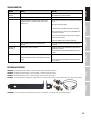
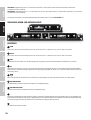
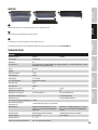
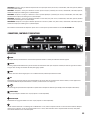
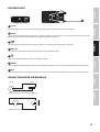
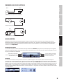
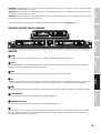
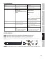
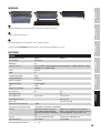
CONNECTIONS, CONTROLS AND INDICATORS
1
2
5
3 4
9
8
1
2
3
4
5
6
7
2
3
4
9
8
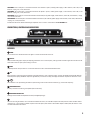
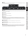
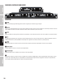
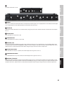
RECEIVER
1
POWER
On / Off switch. Press and hold the switch for approx. 2 seconds to turn the device on or off.
2
DISPLAY
Multi-functional OLED graphics display for displaying information such as radio frequency, radio signal level and audio signal level. Also indicates the
menu items in order to adjust system settings as desired.
3
MENU
Combined pressure rotary encoder to access the Edit menu and to select and edit individual menu items.
4
VOL
Rotary encoder to adjust the audio signal volume of the audio outputs. As soon as volume changes are made, the volume setting will be shown im-
mediately on the display (VOLUME 00 - 100). After approximately 3 seconds of inactivity, the display will automatically return to to the main screen.
5
Infrared interface for synchronising the relevant system settings of the receiver and the transmitter (e.g. transmission frequency).
6
HEADPHONE OUTPUT
6.3 mm jack socket for connecting a headphone (dual receiver only).
7
HEADPHONE VOLUME LEVEL
Drehregler zum Einstellen der Kopfhörerlautstärke (nur Doppelempfänger).
8
Device for attaching the antennas for rack installation. Remove the covers, attach the BNC adapter to the front panel and connect the BNC antenna
connectors (Fig. 11, dual receiver) to the BNC adapters on the front panel (short antenna cable and BNC adapter included). Now, the antennas can be
attached to the front of the receiver.
5
DEUTSCHFRANCAIS
ESPAÑOL
ENGLISH
ITALIANO POLSKI

9
Screw holes for 19” rack mounting.
11
15
16
17
12
13 14
12
13
14
11
10
12
13
14
11
11
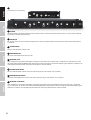
10
10
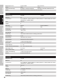
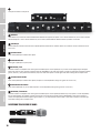
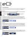
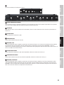
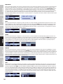
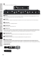
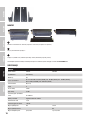
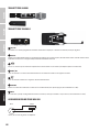
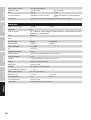
DC SOCKET
Low-voltage socket for the power supply of the device. (Single receiver: DC 12V Plus internal/ 500 mA, Dual receiver: DC 12 V Plus internal/ 1000 mA).
Please only use the power adapter included.
11
ANTENNA A/B
BNC antenna connector A and B. For optimal reception, please connect the supplied antenna to the connectors A and B and point them upward in
“V” formation.
12
BALANCED OUTPUT
Balanced audio output with 3-pin XLR socket.
13
UNBALANCED OUTPUT
Unbalanced audio output with 6.3 mm jack socket.
14
INSTRUMENT / LINE
Level and impedance adjustment to instruments or line inputs for the unbalanced jack output. Using a suitable tool (e.g. a ball point pen), set the
switch to the down position INSTRUMENT, when connecting the receiver to the input of an instrument amplier (guitar amplier, bass amplier) and
to the opposite position LINE, when connecting to the line input of a mixer or amplier
15
BALANCED OUTPUT MIX OUT
Balanced audio output with 3-pin XLR socket (dual receiver only, signals from channels 1 and 2 are mixed).
16
UNBALANCED OUTPUT MIX OUT
Unbalanced audio output with 6.3 mm jack socket (dual receiver only, signals from channels 1 and 2 are mixed).
17
INSTRUMENT / LINE MIX OUT
Level and impedance adjustment to instruments or line inputs for the unbalanced jack output MIX OUT (dual receiver only). Using a suitable tool
(e.g. a ball point pen), set the switch to the down position INSTRUMENT, when connecting the receiver to the input of an instrument amplier (guitar
amplier, bass amplier) and to the opposite position LINE, when connecting to the line input of a mixer or amplier.
6
ITALIANO
POLSKI
ESPAÑOL
FRANCAIS
DEUTSCHENGLISH

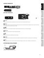
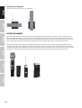
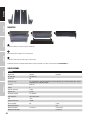
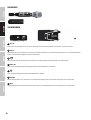
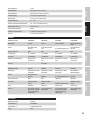
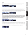
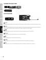
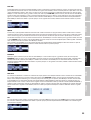
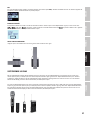
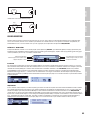
HANDHELD TRANSMITTER
22
21
20
19
18
BELT PACK TRANSMITTER
18
24
21
22
20
19
23
18
ON / OFF
On / Off switch. Set the switch to the ON position to turn the receiver on, and to the OFF position to turn it off.
19
DISPLAY
Multi-functional OLED graphics display for displaying the frequency group and channel, the username and battery status. Also indicates the menu
items in order to adjust transmitter settings as desired.
20
Infrared interface for synchronising the relevant system settings with the receiver (e.g. transmission frequency).
21
MENU / SEL
Switch to access the Edit menu and to select individual menu items.
22
Switch to edit the individual menu options on the Edit menu.
23
ANTENNA
Interchangeable antenna of the belt pack transmitter. For optimal reception, please do not obstruct or bend (belt pack transmitter only).
24
INPUT
3-pin mini XLR socket to connect a headset, lavalier or instrument microphone, as well as a guitar cable (belt pack transmitter only).
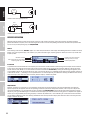
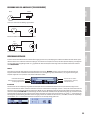
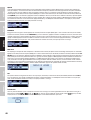
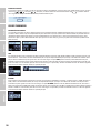
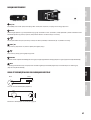
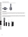
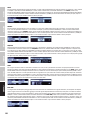
BELTPACK MINI-XLR PIN ASSIGNMENT
1
2
3
MINI-XLR
sleeve tip
6,3 mm jack
Guitar & Bass and other high impendance sources.
7
DEUTSCHFRANCAIS
ESPAÑOL
ENGLISH
ITALIANO POLSKI

1
2
ava3
MINI-XLR
Condenser with internal pull up resistor.
1
2
3
MINI-XLR
R
2,2k
Condenser without internal pull up resistor.
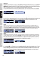
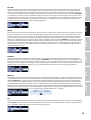
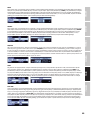
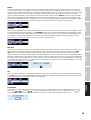
RECEIVER OPERATION
When operating the wireless transmission system, be sure to place the receiver in the line of sight of the transmitter. For optimal reception,
perform the automatic frequency search after switching on the receiver. Leave the corresponding transmitter off, but other radio systems turned
on, if necessary. For the operating steps, see FREQ AUTO RUN.
DISPLAY
After switching on the receiver, “WELCOME” appears for a short time, then the main screen displays the following information: individual username,
battery status, radio signal level (RF), active antenna (A / B), level of the audio signal, frequency group and channel (GR.xx and CH.xx) and the radio
frequency in MHz.
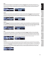
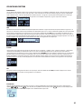
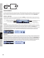
IR SYNC RUN
To synchronize the transmitter with the radio frequency set in the receiver and the individual username, bring the infrared port of the transmitter
in direct visual contact with the infrared port of the receiver (distance approx. 10 cm) and turn on the transmitter. Now press the pressure rotary
encoder of the receiver (MENU) to access the Edit menu and select the menu item IR SYNC RUN by rotating the encoder (light background). Press
again on MENU to initiate the synchronization process. After a few seconds, the process is completed and the display of the transmitter switches for
a short time to “IR SYNC ”, conrming successful synchronization. To cancel the operation, press MENU. Press briey(!) on POWER to return directly
to the main display. After about 10 seconds of inactivity, the main display is automatically shown.
FREQ AUTO RUN
Automatic frequency search (frequency scan) to determine an interference-free radio frequency in the current environment and to allow for
optimal reception. For this purpose, leave the corresponding transmitter off, but other radio systems turned on, if necessary. Press the pressure
rotary encoder (MENU) to access the Edit menu and select the menu item FREQ AUTO RUN by rotating the encoder (light background). To initiate
the process, press again on MENU. Progress is now indicated on the display by an animation and the scanning process is completed after approx. 30
seconds (to cancel, press MENU). The resulting frequency is automatically enabled and, as in “IR SYNC RUN”, you can now switch on the transmitter
and synchronize it with the receiver. Press briey(!) on POWER to return directly to the main display. After about 10 seconds of inactivity, the main
display is automatically shown.
· Individual username
· Radio signal level and active antenna
· Frequency group and channel
· Battery status of the transmitter
· Audio signal level / Peak (PK)
· Radio frequency in MHz
8
ITALIANO
POLSKI
ESPAÑOL
FRANCAIS
DEUTSCHENGLISH

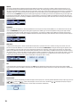
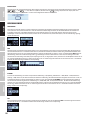
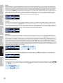
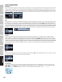
GROUP
Menu item to adjust the frequency group. The LD U500 wireless system has 8 frequency groups, which can be selected as desired. Press the
pressure rotary encoder (MENU) to access the Edit menu and select the menu item GROUP by rotating the encoder (light background). Press MENU
again and select one of the groups 01 to 08 by rotating the encoder. To conrm, press MENU. Pressing MENU once more will take you up one level
in the menu structure. Press briey(!) on POWER to return directly to the main display. After about 10 seconds of inactivity, the main display is
automatically shown.
CHANNEL
Menu item to adjust the frequency channel. The LD U500 wireless system has 8 frequency groups featuring 12 channels each, which can be selected
as desired. Press the pressure rotary encoder (MENU) to access the Edit menu and select the menu item CHANNEL by rotating the encoder (light
background). Press MENU again and select one of the channels 01 to 12 by rotating the encoder. To conrm, press MENU. Pressing MENU once more
will take you up one level in the menu structure. Press briey(!) on POWER to return directly to the main display. After about 10 seconds of inactivity,
the main display is automatically shown.
FREQ MAN
Manual adjustment of the radio frequency in 25 kHz increments. Press the pressure rotary encoder (MENU) to access the Edit menu and select the
menu item FREQ MAN by rotating the encoder (light background). Press MENU and adjust the frequency in the MHz range by rotating the encoder.
Press MENU again and adjust the frequency in the kHz range in 25 kHz increments by rotating the encoder. To conrm, press MENU. Pressing MENU
once more will take you up one level in the menu structure. Press briey(!) on POWER to return directly to the main display. After about 10 seconds
of inactivity, the main display is automatically shown. The display will now show U for user under group GR. and CH.1 under channel.
NAME
To clearly assign transmitters and receivers to a specic performer, you have the ability to show names, numbers, or characters on the display.
Press the pressure rotary encoder (MENU) to access the Edit menu and select the menu item NAME by rotating the encoder (light background).
Press MENU and then, as desired, select the letter, number or symbol for the rst of the 8 digits provided by rotating the encoder and conrming
with MENU; now, the second digit can be set as desired, etc.. Once the last digit has been conrmed, pressing MENU again will take you to a higher
level in the menu structure. Press briey(!) on POWER to return directly to the main display. After about 10 seconds of inactivity, the main display is
automatically shown. In addition to the radio frequency, the name is also transferred to the transmitter when synchronizing.
PILOT TONE
The pilot tone feature protects a wireless microphone system against interference of unwanted signals, for example from other radio equipment.
The transmitter adds a second inaudible signal, the pilot tone, to the signal to be transmitted. The receiver identies this as the matching pilot tone
and frees the corresponding signal. Signals without pilot tone remain muted. Press the pressure rotary encoder (MENU) to access the Edit menu and
select the menu item PILOT TONE by rotating the encoder (light background). Press again on MENU and using the encoder, select ON, for initiating
pilot tone (right turn), or OFF for pilot tone equipment switched off (turn left). To conrm, press MENU. Pressing MENU once more will take you
up one level in the menu structure. Press briey(!) on POWER to return directly to the main display. After about 10 seconds of inactivity, the main
display is automatically shown.
· Battery status of the transmitter
· Audio signal level / Peak (PK)
· Radio frequency in MHz
9
DEUTSCHFRANCAIS
ESPAÑOL
ENGLISH
ITALIANO POLSKI

SQUELCH
The squelch control prevents unwanted background noise when the transmitter is turned off. In addition, sudden background noises are sup-
pressed when the signal transmitted from the transmitter to the receiver is not strong enough (for instance because of excessive distance) Set
the squelch control (with the transmitter switched off) to the lowest setting, which still effectively suppresses background noises. In unfavourable
conditions, in the “HIGH” setting, the transmission range may decrease. Press the pressure rotary encoder (MENU) to access the Edit menu and
select the menu item SQUELCH by rotating the encoder (light background). Press MENU again and select the optimum setting for your application
by rotating the encoder (LOW = low, MID= mid and HIGH = high threshold). To conrm, press MENU. Pressing MENU once more will take you up one
level in the menu structure. Press briey(!) on POWER to return directly to the main display. After about 10 seconds of inactivity, the main display is
automatically shown.
BRIGHTNESS
Menu item to adjust the brightness of the display illumination. Press the pressure rotary encoder (MENU) to access the Edit menu and select the
menu item BRIGHTNESS by rotating the encoder (light background). Press MENU again and select the optimum setting for your application by
rotating the encoder (LOW = low, MID= mid and HIGH = high brightness). To conrm, press MENU. Pressing MENU once more will take you up one
level in the menu structure. Press briey(!) on POWER to return directly to the main display. After about 10 seconds of inactivity, the main display is
automatically shown.
PANEL LOCK
To protect the receiver against accidental and unauthorised operation, it is possible to initiate an automatic locking of the controls. Press the
pressure rotary encoder (MENU) to access the Edit menu and select the menu item PANEL LOCK by rotating the encoder (light background). Press
again on MENU and using the encoder, select ON, for initiating the automatic lock (right turn), or OFF to switch it off (turn left). To conrm, press
MENU. Pressing MENU once more will take you up one level in the menu structure. Press briey(!) on POWER to return directly to the main display. If
the automatic lock is activated, after approx. 10 seconds, “DISPLAY IS LOCKED” is displayed for a short time and also if one of the controls is activated;
a change to the settings of the receiver via the control elements is then not possible. Press and hold the pressure rotary encoder for approx. 3
seconds to unlock the control elements (“DISPLAY IS UNLOCKED” is displayed for about 1 second).
EXIT
To exit the Edit menu and return to the main display, select EXIT (light background) by rotating the pressure rotary encoder and press MENU.
Alternatively, press briey(!) on POWER to return directly to the main display. After about 10 seconds of inactivity, the main display is automatically
shown.
BATTERY STATUS
The battery status of the corresponding transmitter will appear on the display and is constantly updated. When the battery is fully charged, the icon
( = approx. 70%, = approx. 30%) will appear. As soon as the icon for “low battery” is displayed, the display changes to
“LOW BATTERY” and shows approximately every 5 seconds. Replace the batteries immediately.
10
ITALIANO
POLSKI
ESPAÑOL
FRANCAIS
DEUTSCHENGLISH

TRANSMITTER OPERATION
MAIN DISPLAY
After switching on the transmitter, the main screen displays the following information: username, frequency group and channel (GR.xx and CH.xx)
and battery status. Remove the battery compartment cover on the transmitter to release the controls SEL and arrow buttons (hand-held
transmitter: remove the screwable cover shell by rotating it to the left, belt pack transmitter: pull cover shell by pressing on the markings on the
sides of the housing). Now press the arrow button, and the radio frequency, gain and transmission power are displayed (back with arrow button).
GAIN
To avoid distortions and to adjust the transmitter optimally to the input audio signal, it is possible to adjust the audio levels in 3dB increments
from 0dB to -27dB. Open the battery compartment cover as previously described to reveal the controls. Press SEL to access the Edit menu and press
SEL repeatedly, if necessary, to select the menu item GAIN (light background). Now lower the audio level if necessary by repeatedly pressing the
arrow button until you have no more distortion and the peak indicator AF PK in the display of the receiver goes out (watch out for peak levels). To
exit the menu item, press SEL, call up the menu item EXIT by pressing SEL repeatedly if necessary, and conrm by pressing the arrow button. After
approximately 10 seconds of inactivity, the display will automatically return to the main screen.
RF POWER
Adjust the output power of the transmitter according to the application (recommendation: outdoors = 30mW, stage = 10mW, conference setting
= 2mW). Open the battery compartment cover as previously described to reveal the controls. Press SEL to access the Edit menu and press SEL
repeatedly, if necessary, to select the menu item RF POWER (light background). Now, using the arrow keys, select the desired output power (30mW,
10mW, 2mW - in the frequency range of 863 – 865 MHz, the output power is automatically reduced to 10 mW in accordance with legal requirements).
To exit the menu item, press SEL, call up the menu item EXIT by pressing SEL repeatedly if necessary, and conrm by pressing the arrow button. After
approximately 10 seconds of inactivity, the display will automatically return to the main screen.
EXIT
In order to exit the Edit menu and return to the main display, call up the menu item EXIT and conrm by pressing the arrow button.
After approximately 10 seconds of inactivity, the display will automatically return to the main screen.
BATTERY STATUS
The battery status of the transmitter will appear in the display and is constantly updated. When the battery is fully charged, the icon
(
= approx. 70%,
= approx. 30%) will appear. As soon as the icon for “low battery” is displayed, the display changes to “LOW BATTERY” and
shows approximately every 5 seconds. Replace the batteries immediately.
11
DEUTSCHFRANCAIS
ESPAÑOL
ENGLISH
ITALIANO POLSKI

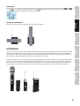
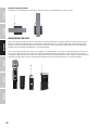
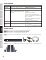
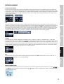
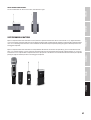
ATTACHING THE PACK TRANSMITTER
Attach the transmitter to a belt or strap as shown below.
BATTERY REPLACEMENT
Open the battery compartment of the hand-held transmitter by turning the battery compartment cover counter-clockwise and pull it from the
housing. Remove the used batteries and insert new batteries (AA, Mignon) as shown on the illustration inside the battery compartment. Replace
the battery compartment cover on the housing and close the battery compartment by turning clockwise. If the transmitter is not in use for a long
period of time, remove the batteries from the battery compartment on the transmitter to avoid damage caused by defective batteries.
Open the battery compartment of the hand-held transmitter by pressing on both markings on the sides of the battery compartment cover (Fig.
A) and pull it away until it stops. Remove the used batteries and insert new batteries (AA, Mignon) as shown on the illustration inside the battery
compartment. Slide the battery compartment cover back onto the housing until the cover clicks into place. If the transmitter is not in use for a long
period of time, remove the batteries from the battery compartment on the transmitter to avoid damage caused by defective batteries.
A
12
ITALIANO
POLSKI
ESPAÑOL
FRANCAIS
DEUTSCHENGLISH

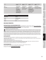
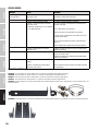
TROUBLESHOOTING
PROBLEM DISPLAY SOLUTION
No audio signal or
low level
Receiver: Reception is not displayed on antenna A or B. Verify that the transmitter is turned on.
Check the batteries in the transmitter.
Receiver: Display light is off Check the power supply in the transmitter.
Receiver: Reception is not displayed on antenna A or B.
Transmitter: Device is turned on. Charge status of the
batteries is ok.
Check whether radio frequency of transmitter and receiver
match.
Check the transmission output.
Reduce the distance between transmitter and receiver.
Make sure that there is a direct line of sight between the
transmitter and receiver.
Make sure that the antennas of the receiver are aligned
upward and into a V-shape.
Reduce the amount of noise reduction (SQUELCH)
Receiver: Neither antenna A nor antenna B LED is
displayed.
Increase the signal level or check the GAIN setting on the
transmitter.
Distortion and
interference
Receiver: Radio signal is displayed Remove possible sources of interference (digital devices,
other wireless systems).
Increase the level of noise reduction (MUTE level) on the
receiver.
Distorted sound Transmitter and Receiver: "LOW BATTERY" is displayed.
Receiver: AF PK peak indicator is displayed on the receiver
display.
Replace the batteries in the transmitter.
Increase the signal level or lower the audio level GAIN on
the transmitter.
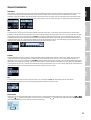
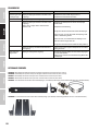
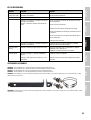
OPTIONAL ACCESSORIES
LDU500CH - Microphone head with condenser capsule and hyper cardioid directivity (matt black)
LDU500DH - Microphone head with dynamic capsule and hyper cardioid directivity (matt black)
LDU500CC - Microphone head with condenser capsule and hyper cardioid directivity (matt silver)
LDU500DC - Microphone head with dynamic capsule and hyper cardioid directivity (matt silver)
LDU500RK - 19” rack installation kit for mounting a single receiver (2 rack brackets, 2 BNC adapters, 2 short antenna cables and 1 set of screws included).
LDU500RK2 - 19” rack installation kit for mounting a dual receiver (2 rack brackets, 2 connectors and 1 set of screws included).
13
DEUTSCHFRANCAIS
ESPAÑOL
ENGLISH
ITALIANO POLSKI

MOUNTING
1 2 3
1
Screw the connectors (receiver A right, receiver B left).
2
Place both receivers together and screw into place.
3
Screw the rack brackets (receiver A right, receiver B left).
An extensive selection of suitable LD U500 wireless systems and further accessories can be found at www.LD-SYSTEMS.COM
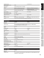
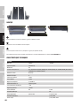
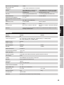
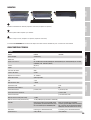
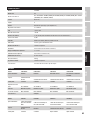
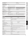
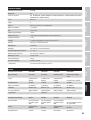
SPECIFICATIONS
Receiver
Model name: LDU50xR LDU50xR2
Receiver type: true diversity
Modulation: FM
Frequency range: 823 - 832 MHz & 863 - 865 MHz (LDU508), 584 - 607 MHz (LDU505), 655 - 679 MHz (LDU506), 604 - 614 MHz
(LDU506UK), 1785 - 1800 MHz (LDU518)
Channels: 96 (8 x 12)
Groups: 8
Antenna connectors: 2 x BNC
Antenna Gain: 2.15 dBi
Frequency response: 30 - 16.000 Hz
Noise Reduction: adjustable squelch
THD: <0.1%
Signal-to-noise ratio: >100dB
Balanced output: XLR 2 x XLR
Balanced mix output: XLR
Unbalanced output: 6.3 mm jack 2x 6.3mm jack
Unbalanced mix output: 6.3 mm jack
14
ITALIANO
POLSKI
ESPAÑOL
FRANCAIS
DEUTSCHENGLISH

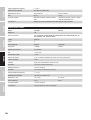
Headphones output: 6.3 mm stereo jack
Audio output level (balanced): +10dBu
Audio output level
(unbalanced):
+6dBV / 0dBV (Switchable Line / Instrument)
Controls: POWER on/off, MENU push-turn-control, VOL
Volume control, switch INSTRUMENT/LINE
POWER on/off, 2x MENU push-turn-control, 2x
VOL Volume control, 2x switch INSTRUMENT/LINE,
headphones volume control
Indicators: multifunctional OLED-graphic display, 2 x multifunctional OLED-graphic display
Operating voltage: 12V DC, 500 mA 12V DC, 1000 mA
Operating temperature range: 5°C … 40°C
Relative humidity in operation: 20% … 80% (non condensing)
Dimensions (W x H x D): 212 x 44 x 159mm 484 x 44 x 200mm
Weight: 0.95kg 2.05 kg
Accessories included: power adapter, 2 x antenna, audio cable power adapter, 2 x antenna, audio cable, rack kit
Features: channel scan function, infrared frequency synchronisation, pilot tone
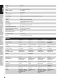
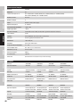
Handheld transmitter
Model name: LDU50xMD LDU50xMC
Modulation: FM
Frequency range: 823 - 832 MHz & 863 - 865 MHz (LDU508), 584 - 607 MHz (LDU505), 655 - 679 MHz (LDU506),
604 - 614 MHz (LDU506UK), 1785 - 1800 MHz (LDU518)
Channels: 96 (8 x 12)
Groups: 8
Microphone type: dynamic condenser
Polar pattern: cardioid cardioid
Frequency response: 60 - 16.000 Hz
THD: <0.2% @ 1kHz
Signal-to-noise ratio: >95 dB
RF output power: 2mW, 10mW, 30mW switchable and depending on the RF -Range
Antenna Gain: 0.5 dBi
Controls: Power on/off, Select, Arrow button
Indicators: multifunctional OLED-graphic display
Power supply: 2 x AA battery
Operating time: up to 10 h (depending on batteries)
Operating temperature range: 5°C … 40°C
Relative humidity range in operation: 20% … 80% (non condensing)
Dimensions (L x Ø): 257 x 51mm 257 x 50mm
Weight (without batteries): 0.2 kg 0.21kg
Accessories included: 2 x AA battery
Features: infrared frequency synchronisation
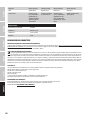
Bodypack transmitter
Model name: LDU50xBP
Modulation: FM
Frequency range: 823 - 832 MHz & 863 - 865 MHz (LDU508), 584 - 607 MHz (LDU505), 655 - 679 MHz (LDU506), 604 - 614 MHz
(LDU506UK), 1785 - 1800 MHz (LDU518)
15
DEUTSCHFRANCAIS
ESPAÑOL
ENGLISH
ITALIANO POLSKI

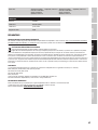
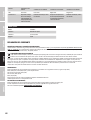
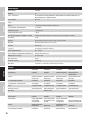
Microphones
Model name: LDWS100MH1 LDWS100MH3 LDWS100ML LDWS1000MW
Microphone type: headset headset lavalier microphone wind instrument
microphone
Capsule: back-electret condenser back-electret condenser back-electret condenser back-electret condenser
Polar pattern: cardioid cardioid cardioid cardioid
Frequency response: 20 - 20.000 Hz 70 - 16.000 Hz 20 - 20.000 Hz 50 - 18.000 Hz
Connector: 3-pin mini-XLR 3-pin mini-XLR 3-pin mini-XLR 3-pin mini-XLR
Accessories included: foam windscreen foam windscreen foam windscreen foam windscreen
Features: skin coloured
Model name: LDU500CC LDU500DC LDU500CH LDU500DH
Microphone type: Microphone head for
U500 handheld
Microphone head for
U500 handheld
Microphone head for
U500 handheld
Microphone head for
U500 handheld
Capsule: back-electret condenser dynamic back-electret condenser dynamic
Polar pattern: cardioid cardioid hyper cardioid hyper cardioid
Connector: LDU500 screw connection LDU500 screw connection LDU500 screw connection
LDU500 screw
connection
Colour: matt silver matt silver matt black matt black
Features: low noise -FET impedan-
ce converter, customized
shock mount, gold
contacts
shock mount, gold
contacts
low noise -FET impedan-
ce converter, customized
shock mount, gold
contacts
shock mount, gold
contacts
Channels: 96 (8 x 12)
Groups: 8
Input: 3-pin mini-XLR (Low-Z/High-Z)
Frequency response: 30 - 16.000 Hz
THD: <0.1% @ 1kHz
Signal-to-noise ratio: >90 dB
RF output power: 2mW, 10mW, 30mW switchable and depending on the RF -Range
Antenna Gain: 0.5 dBi
Controls: Power on/off, Select, Arrow button
Indicators: multifunctional OLED-graphic display
Power supply: 2 x AA batteries
Operating time: up to 10 h (depending on batteries)
Operating temperature range: 5°C … 40°C
Relative humidity range in operation: 20% … 80% (non condensing)
Dimensions (W x H x D): 65 x 86 x 23 mm
Weight (without batteries): 0,09 kg
Accessories included: 2 x AA battery
Features: infrared frequency synchronisation
16
ITALIANO
POLSKI
ESPAÑOL
FRANCAIS
DEUTSCHENGLISH

Guitar cable
Model name: LDU500GC
Connector 1: 3-pin mini-XLR
Connector 2: 6.3 mm jack
Length: 0.8 m
MANUFACTURER´S DECLARATIONS
MANUFACTURER‘S WARRANTY & LIMITATIONS OF LIABILITY
You can nd our current warranty conditions and limitations of liability at: https://cdn-shop.adamhall.com/media/pdf/MANUFACTURERS-DECLARA-
TIONS_LD_SYSTEMS.pdf To request warranty service for a product, please contact Adam Hall GmbH, Adam-Hall-Str. 1,
61267 Neu Anspach / Email: [email protected] / +49 (0)6081 / 9419-0.
CORRECT DISPOSAL OF THIS PRODUCT
(valid in the European Union and other European countries with a differentiated waste collection system)
This symbol on the product, or on its documents indicates that the device may not be treated as household waste. This is to avoid environ-
mental damage or personal injury due to uncontrolled waste disposal. Please dispose of this product separately from other waste and have it
recycled to promote sustainable economic activity. Household users should contact either the retailer where they purchased this product, or their
local government ofce, for details on where and how they can recycle this item in an environmentally friendly manner. Business users should
contact their supplier and check the terms and conditions of the purchase contract. This product should not be mixed with other commercial waste
for disposal.
FCC STATEMENT
This device complies with Part 15 of the FCC Rules. Operation is subject to the following two conditions:
(1) This device may not cause harmful interference, and
(2) This device must accept any interference received, including interference that may cause undesired operation
CE Compliance
Adam Hall GmbH states that this product meets the following guidelines (where applicable):
R&TTE (1999/5/EC) or RED (2014/53/EU) from June 2017
Low voltage directive (2014/35/EU)
EMV directive (2014/30/EU)
RoHS (2011/65/EU)
The complete declaration of conformity can be found at www.adamhall.com.
Furthermore, you may also direct your enquiry to [email protected].
EU DECLARATION OF CONFORMITY
Hereby, Adam Hall GmbH declares that this radio equipment type is in compliance with Directive 2014/53/EU.
The full text of the EU declaration of conformity is available at the following
internet address: www.adamhall.com/compliance/
17
DEUTSCHFRANCAIS
ESPAÑOL
ENGLISH
ITALIANO POLSKI

DEUTSCH
Sie haben die richtige Wahl getroffen!
Dieses Gerät wurde unter hohen Qualitätsanforderungen entwickelt und gefertigt, um viele Jahre einen reibungslosen Betrieb zu gewährleisten.
Dafür steht LD Systems mit seinem Namen und der langjährigen Erfahrung als Hersteller hochwertiger Audioprodukte. Bitte lesen Sie diese Bedie-
nungsanleitung sorgfältig, damit Sie Ihr neues Produkt von LD Systems schnell optimal einsetzen können.
Mehr Informationen zu LD SYSTEMS nden Sie auf unserer Internetseite www.LD-SYSTEMS.COM
SICHERHEITSHINWEISE
1. Lesen Sie diese Anleitung bitte sorgfältig durch.
2. Bewahren Sie alle Informationen und Anleitungen an einem sicheren Ort auf.
3. Befolgen Sie die Anweisungen.
4. Beachten Sie alle Warnhinweise. Entfernen Sie keine Sicherheitshinweise oder andere Informationen vom Gerät.
5. Verwenden Sie das Gerät nur in der vorgesehenen Art und Weise.
6. Verwenden Sie ausschließlich stabile und passende Stative bzw. Befestigungen (bei Festinstallationen). Stellen Sie sicher, dass Wandhalterungen
ordnungsgemäß installiert und gesichert sind. Stellen Sie sicher, dass das Gerät sicher installiert ist und nicht herunterfallen kann.
7. Beachten Sie bei der Installation die für Ihr Land geltenden Sicherheitsvorschriften.
8. Installieren und betreiben Sie das Gerät nicht in der Nähe von Heizkörpern, Wärmespeichern, Öfen oder sonstigen Wärmequellen. Sorgen Sie dafür,
dass das Gerät immer so installiert ist, dass es ausreichend gekühlt wird und nicht überhitzen kann.
9. Platzieren Sie keine Zündquellen wie z.B. brennende Kerzen auf dem Gerät.
10. Lüftungsschlitze dürfen nicht blockiert werden.
11. Betreiben Sie das Gerät nicht in unmittelbarer Nähe von Wasser. Bringen Sie das Gerät nicht mit brennbaren Materialien, Flüssigkeiten oder Gasen
in Berührung. Direkte Sonneneinstrahlung vermeiden!
12. Sorgen Sie dafür, dass kein Tropf- oder Spritzwasser in das Gerät eindringen kann. Stellen Sie keine mit Flüssigkeit gefüllten Behältnisse wie
Vasen oder Trinkgefäße auf das Gerät.
13. Sorgen Sie dafür, dass keine Gegenstände in das Gerät fallen können.
14. Betreiben Sie das Gerät nur mit dem vom Hersteller empfohlenen und vorgesehenen Zubehör.
15. Öffnen Sie das Gerät nicht und verändern Sie es nicht.
16. Überprüfen Sie nach dem Anschluss des Geräts alle Kabelwege, um Schäden oder Unfälle, z. B. durch Stolperfallen zu vermeiden.
17. Achten Sie beim Transport darauf, dass das Gerät nicht herunterfallen und dabei möglicherweise Sach- und Personenschäden verursachen kann.
18. Wenn Ihr Gerät nicht mehr ordnungsgemäß funktioniert, Flüssigkeiten oder Gegenstände in das Geräteinnere gelangt sind, oder das Gerät an-
derweitig beschädigt wurde, schalten Sie es sofort aus und trennen es von der Netzsteckdose (sofern es sich um ein aktives Gerät handelt). Dieses
Gerät darf nur von autorisiertem Fachpersonal repariert werden.
19. Verwenden Sie zur Reinigung des Geräts ein trockenes Tuch.
20. Beachten Sie alle in Ihrem Land geltenden Entsorgungsgesetze. Trennen Sie bei der Entsorgung der Verpackung bitte Kunststoff und Papier bzw.
Kartonagen voneinander.
21. Kunststoffbeutel müssen außer Reichweite von Kindern aufbewahrt werden.
BEI GERÄTEN MIT NETZANSCHLUSS
22. ACHTUNG: Wenn das Netzkabel des Geräts mit einem Schutzkontakt ausgestattet ist, muss es an einer Steckdose mit Schutzleiter angeschlossen
werden. Deaktivieren Sie niemals den Schutzleiter eines Netzkabels.
23. Schalten Sie das Gerät nicht sofort ein, wenn es starken Temperaturschwankungen ausgesetzt war (beispielsweise nach dem Transport). Feuch-
tigkeit und Kondensat könnten das Gerät beschädigen. Schalten Sie das Gerät erst ein, wenn es Zimmertemperatur erreicht hat.
24. Bevor Sie das Gerät an die Steckdose anschließen, prüfen Sie zuerst, ob die Spannung und die Frequenz des Stromnetzes mit den auf dem Gerät
angegebenen Werten übereinstimmen. Verfügt das Gerät über einen Spannungswahlschalter, schließen Sie das Gerät nur an die Steckdose an,
wenn die Gerätewerte mit den Werten des Stromnetzes übereinstimmen. Wenn das mitgelieferte Netzkabel bzw. der mitgelieferte Netzadapter
nicht in Ihre Netzsteckdose passt, wenden Sie sich an Ihren Elektriker.
25. Treten Sie nicht auf das Netzkabel. Sorgen Sie dafür, dass spannungsführende Kabel speziell an der Netzbuchse bzw. am Netzadapter und der
Gerätebuchse nicht geknickt werden.
26. Achten Sie bei der Verkabelung des Geräts immer darauf, dass das Netzkabel bzw. der Netzadapter stets frei zugänglich ist. Trennen Sie das Gerät
stets von der Stromzuführung, wenn das Gerät nicht benutzt wird, oder Sie das Gerät reinigen möchten. Ziehen Sie Netzkabel und Netzadapter immer am
Stecker bzw. am Adapter und nicht am Kabel aus der Steckdose. Berühren Sie Netzkabel und Netzadapter niemals mit nassen Händen.
27. Schalten Sie das Gerät möglichst nicht schnell hintereinander ein und aus, da sonst die Lebensdauer des Geräts beeinträchtigt werden könnte.
28. WICHTIGER HINWEIS: Ersetzen Sie Sicherungen ausschließlich durch Sicherungen des gleichen Typs und Wertes. Sollte eine Sicherung wiederholt
auslösen, wenden Sie sich bitte an ein autorisiertes Servicezentrum.
29. Um das Gerät vollständig vom Stromnetz zu trennen, entfernen Sie das Netzkabel bzw. den Netzadapter aus der Steckdose.
30. Wenn Ihr Gerät mit einem verriegelbaren Netzanschluss bestückt ist, muss der passende Gerätestecker entsperrt werden, bevor er entfernt wer-
den kann. Das bedeutet aber auch, dass das Gerät durch ein Ziehen am Netzkabel verrutschen und herunterfallen kann, wodurch Personen verletzt
werden und/oder andere Schäden auftreten können. Verlegen Sie Ihre Kabel daher immer sorgfältig.
31. Entfernen Sie Netzkabel und Netzadapter aus der Steckdose bei Gefahr eines Blitzschlags oder wenn Sie das Gerät länger nicht verwenden.
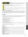
ACHTUNG
Entfernen Sie niemals die Abdeckung, da sonst das Risiko eines elektrischen Schlages besteht. Im Inneren
des Geräts benden sich keine Teile, die vom Bediener repariert oder gewartet werden können. Lassen Sie
Wartung und Reparaturen ausschließlich von qualiziertem Servicepersonal durchführen.
18
ITALIANO
POLSKI
ESPAÑOL
FRANCAIS
DEUTSCHENGLISH

Das gleichseitige Dreieck mit Blitzsymbol warnt vor nichtisolierten, gefährlichen Spannungen im Geräteinneren, die einen elektrischen
Schlag verursachen können.
Das gleichseitige Dreieck mit Ausrufungszeichen kennzeichnet wichtige Bedienungs- und Wartungshinweise.
Warnung! Dieses Symbol kennzeichnet heiße Oberächen. Während des Betriebs können bestimmte Teile des Gehäuses heiß werden.
Berühren oder transportieren Sie das Gerät nach einem Einsatz erst nach einer Abkühlzeit von mindestens 10 Minuten.
ACHTUNG HOHE LAUTSTÄRKEN BEI AUDIOPRODUKTEN!
Dieses Gerät ist für den professionellen Einsatz vorgesehen. Der kommerzielle Betrieb dieses Geräts unterliegt den jeweils gültigen nationalen Vorschriften
und Richtlinien zur Unfallverhütung. Als Hersteller ist Adam Hall gesetzlich verpichtet, Sie ausdrücklich auf mögliche Gesundheitsrisiken hinzuweisen.
Gehörschäden durch hohe Lautstärken und Dauerbelastung: Bei der Verwendung dieses Produkts können hohe Schalldruckpegel (SPL) erzeugt werden, die
bei Künstlern, Mitarbeitern und Zuschauern zu irreparablen Gehörschäden führen können. Vermeiden Sie länger
anhaltende Belastung durch hohe Lautstärken über 90 dB.
EINFÜHRUNG
Die Funkübertragungssysteme der LD U500 Serie bieten professionelle Leistung und Funktionen einschließlich der automatischen Kanalsuche und
der bequemen One-Touch-Infrarot-Synchronisierung für einfache Einrichtung. Mit schaltbarer HF-Leistung, Pilotton-Übertragung und einer Auswahl
von dynamischen und Kondensatormikrofonen liefern U500 Systeme hervorragenden Klang mit erweiterter Dynamik.
• Drahtloses True Diversity UHF Mikrofon System
• Automatischer Kanal-Scan für interferenzfreie Funktion
• Frequenz-Sync via Infrarot-Technik
• Individueller Benutzername
• Pilot-Ton für störgeräuschfreie Übertragung
• Einstellbare Rauschsperre (Squelch)
• Schaltbare Sendeleistung (2, 10 oder 30 mW)
• Hand- und Taschensender mit komfortabler Gain-Einstellung
• Mechanisch entkoppelte Kapseln
• Kontrastreiches OLED-Grakdisplay
• Simultaner Betrieb von bis zu 4 Systemen (LDU518) / bis zu 6 Systemen (LDU508 und DU506UK) / bis zu 12 Systemen (LDU505 und LDU506)
Die Verwendung von drahtlosen Mikrofonsystemen kann eine Genehmigung erfordern - je nach landesspezischen Bestimmungen. Bitte kontaktier-
en Sie Ihre zuständigen Behörde für weitere Informationen.
LIEFERUMFANG
LDU5xxHHC: Einzelempfänger plus Handsender und Kondensatorkapsel (cardioid), Netzteil, 2x BNC-Antennen, Audiokabel, 2x AA Batterien, Transport-
koffer, Anleitung
LDU5xxHHD: Einzelempfänger plus Handsender und dynamischer Kapsel (cardioid), Netzteil, 2x BNC-Antennen, Audiokabel, 2x AA Batterien, Trans-
portkoffer, Anleitung
LDU5xxBPH: Einzelempfänger plus Taschensender und Headset (schwarz), Netzteil, 2x BNC-Antennen, Audiokabel, 2x AA Batterien,
Transportkoffer, Anleitung
LDU5xxBPHH: Einzelempfänger plus Taschensender und Headset (hautfarben), Netzteil, 2x BNC-Antennen, Audiokabel, 2x AA Batterien,
Transportkoffer, Anleitung
LDU5xxBPG: Einzelempfänger plus Taschensender und Gitarrenkabel, Netzteil, 2x BNC-Antennen, Audiokabel, 2x AA Batterien,
Transportkoffer, Anleitung
LDU5xxBPL: Einzelempfänger plus Taschensender und Lavalier-Mikrofon, Netzteil, 2x BNC-Antennen, Audiokabel, 2x AA Batterien,
Transportkoffer, Anleitung
LDU5xxBPW: Einzelempfänger plus Taschensender und Clip-Mikrofon für Blasinstrumente, Netzteil, 2x BNC-Antennen, Audiokabel, 2x AA Batterien,
Transportkoffer, Anleitung
LDU5xxHHC2: Doppelempfänger plus 2x Handsender und Kondensatorkapsel (cardioid), Netzteil, 2x BNC-Antennen, Audiokabel, 4x AA Batterien,
Transportkoffer, Rack-Kit, Anleitung
LDU5xxHHD2: Doppelempfänger plus 2x Handsender und dynamischer Kapsel (cardioid), Netzteil, 2x BNC-Antennen, Audiokabel, 4x AA Batterien,
Transportkoffer, Rack-Kit, Anleitung
19
DEUTSCHFRANCAIS
ESPAÑOL
ENGLISH
ITALIANO POLSKI

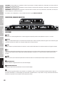
ANSCHLÜSSE, BEDIEN- UND ANZEIGEELEMENTE
LDU5xxBPH2: Doppelempfänger plus 2x Taschensender und Headset (schwarz), Netzteil, 2x BNC-Antennen, Audiokabel, 4x AA Batterien,
Transportkoffer, Rack-Kit, Anleitung
LDU5xxBPHH2: Doppelempfänger plus 2x Taschensender und Headset (hautfarben), Netzteil, 2x BNC-Antennen, Audiokabel, 4x AA Batterien,
Transportkoffer, Rack-Kit, Anleitung
Eine umfangreiche Auswahl an LD U500 Einzelkomponenten und Zubehör nden Sie auf www.LD-SYSTEMS.COM
1
2
5
3
4
9
8
1
2
3
4
5
6
7
2
3
4
9
8
EMPFÄNGER
1
POWER
Ein- bzw. Ausschalter. Drücken und halten Sie den Taster für die Dauer von ca. 2 Sekunden, um das Gerät ein- bzw. auszuschalten.
2
DISPLAY
Ein- bzw. Ausschalter. Drücken und halten Sie den Taster für die Dauer von ca. 2 Sekunden, um das Gerät ein- bzw. auszuschalten.
3
MENU
Kombinierter Drück-Dreh-Geber, um in das Bearbeitungsmenü zu gelangen und die einzelnen Menüpunkte auszuwählen und zu editieren.
4
VOL
Dreh-Geber zum Einstellen der Lautstärke des an den Audio-Ausgängen anliegenden Audio-Signals. Sobald Lautstärkeänderungen vorgenommen
werden, wird die Lautstärkeeinstellung augenblicklich im Display angezeigt (VOLUME 00 - 100). Nach ca. 3 Sekunden Inaktivität kehrt das Display zur
Hauptanzeige zurück.
5
Infrarot-Schnittstelle zum Synchronisieren der relevanten Systemeinstellungen des Empfängers mit dem Sender (z.B. Sendefrequenz).
6
KOPFHÖRERAUSGANG
6,3mm Klinkenbuchse zum Anschließen eines Kopfhörers (nur Doppelempfänger).
7
KOPFHÖRERLAUTSTÄRKE
Drehregler zum Einstellen der Kopfhörerlautstärke (nur Doppelempfänger).
8
Vorrichtung zum Anbringen der Antennen beim Rackeinbau. Entfernen Sie die Abdeckkappen, befestigen die BNC-Adapter an der Frontblende und
verbinden die BNC-Antennenanschlüsse (Abb. 11, Doppelempfänger) mit den BNC-Adaptern in der Frontblende (kurze Antennenkabel und BNC-Adap-
ter im Lieferumfang). Nun können die Antennen an der Vorderseite des Empfängers befestigt werden.
9
Schraublöcher für den 19“ Rackeinbau.
20
ITALIANO
POLSKI
ESPAÑOL
FRANCAIS
DEUTSCHENGLISH
Strona się ładuje...
Strona się ładuje...
Strona się ładuje...
Strona się ładuje...
Strona się ładuje...
Strona się ładuje...
Strona się ładuje...
Strona się ładuje...
Strona się ładuje...
Strona się ładuje...
Strona się ładuje...
Strona się ładuje...
Strona się ładuje...
Strona się ładuje...
Strona się ładuje...
Strona się ładuje...
Strona się ładuje...
Strona się ładuje...
Strona się ładuje...
Strona się ładuje...
Strona się ładuje...
Strona się ładuje...
Strona się ładuje...
Strona się ładuje...
Strona się ładuje...
Strona się ładuje...
Strona się ładuje...
Strona się ładuje...
Strona się ładuje...
Strona się ładuje...
Strona się ładuje...
Strona się ładuje...
Strona się ładuje...
Strona się ładuje...
Strona się ładuje...
Strona się ładuje...
Strona się ładuje...
Strona się ładuje...
Strona się ładuje...
Strona się ładuje...
Strona się ładuje...
Strona się ładuje...
Strona się ładuje...
Strona się ładuje...
Strona się ładuje...
Strona się ładuje...
Strona się ładuje...
Strona się ładuje...
Strona się ładuje...
Strona się ładuje...
Strona się ładuje...
Strona się ładuje...
Strona się ładuje...
Strona się ładuje...
Strona się ładuje...
Strona się ładuje...
Strona się ładuje...
Strona się ładuje...
Strona się ładuje...
Strona się ładuje...
Strona się ładuje...
Strona się ładuje...
Strona się ładuje...
Strona się ładuje...
Strona się ładuje...
Strona się ładuje...
Strona się ładuje...
Strona się ładuje...
Strona się ładuje...
Strona się ładuje...
Strona się ładuje...
Strona się ładuje...
Strona się ładuje...
Strona się ładuje...
Strona się ładuje...
Strona się ładuje...
-
 1
1
-
 2
2
-
 3
3
-
 4
4
-
 5
5
-
 6
6
-
 7
7
-
 8
8
-
 9
9
-
 10
10
-
 11
11
-
 12
12
-
 13
13
-
 14
14
-
 15
15
-
 16
16
-
 17
17
-
 18
18
-
 19
19
-
 20
20
-
 21
21
-
 22
22
-
 23
23
-
 24
24
-
 25
25
-
 26
26
-
 27
27
-
 28
28
-
 29
29
-
 30
30
-
 31
31
-
 32
32
-
 33
33
-
 34
34
-
 35
35
-
 36
36
-
 37
37
-
 38
38
-
 39
39
-
 40
40
-
 41
41
-
 42
42
-
 43
43
-
 44
44
-
 45
45
-
 46
46
-
 47
47
-
 48
48
-
 49
49
-
 50
50
-
 51
51
-
 52
52
-
 53
53
-
 54
54
-
 55
55
-
 56
56
-
 57
57
-
 58
58
-
 59
59
-
 60
60
-
 61
61
-
 62
62
-
 63
63
-
 64
64
-
 65
65
-
 66
66
-
 67
67
-
 68
68
-
 69
69
-
 70
70
-
 71
71
-
 72
72
-
 73
73
-
 74
74
-
 75
75
-
 76
76
-
 77
77
-
 78
78
-
 79
79
-
 80
80
-
 81
81
-
 82
82
-
 83
83
-
 84
84
-
 85
85
-
 86
86
-
 87
87
-
 88
88
-
 89
89
-
 90
90
-
 91
91
-
 92
92
-
 93
93
-
 94
94
-
 95
95
-
 96
96


LD Systems LDSystems U505HHC Handheld Condenser Wireless Microphone System Instrukcja obsługi
- Typ
- Instrukcja obsługi
w innych językach
- español: LD Systems LDSystems U505HHC Handheld Condenser Wireless Microphone System Manual de usuario
- italiano: LD Systems LDSystems U505HHC Handheld Condenser Wireless Microphone System Manuale utente
- Deutsch: LD Systems LDSystems U505HHC Handheld Condenser Wireless Microphone System Benutzerhandbuch
- français: LD Systems LDSystems U505HHC Handheld Condenser Wireless Microphone System Manuel utilisateur
- English: LD Systems LDSystems U505HHC Handheld Condenser Wireless Microphone System User manual
Powiązane artykuły
-
LD Systems U508 BPH Instrukcja obsługi
-
LD LDHP550E Instrukcja obsługi
-
LD LDU505CS4 Instrukcja obsługi
-
LD WS10002 Instrukcja obsługi
-
-
LD U505.1 IEM R Instrukcja obsługi
-
-
-
LD U304.7 BPG Instrukcja obsługi
-
LD Systems U306 HHD Wireless Handheld Microphone System Instrukcja obsługi