
BENNING MM 4
D
Bedienungsanleitung
Operating manual
F
Notice d‘emploi
E
Instrucciones de servicio
Návod k obsluze
Εγχειρίδιο Χρήσης για
H
Kezelési utasítás
I
Istruzioni d’uso
Gebruiksaanwijzing
Instrukcja obsługi
Instructiuni de folosire
Инструкция по эксплуатации
индикатора напряжения
S
Bruksanvisning
Kullanma Talimati

11/ 2008
BENNING MM 4
D F E H I S
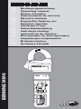
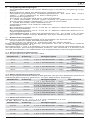
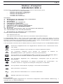
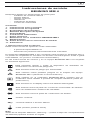
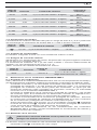
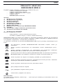
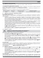
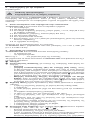
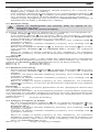
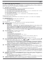
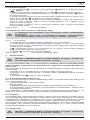
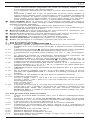
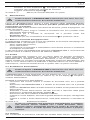
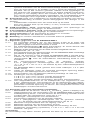
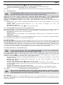
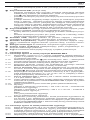
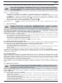
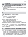
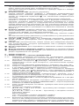
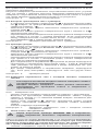
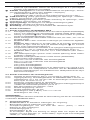
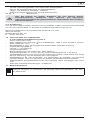
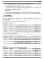
Bild 1: Gerätefrontseite
Fig. 1: Front tester panel
Fig. 1: Panneau avant de l‘appareil
Fig. 1: Parte frontal del equipo
Obr.1: Přední strana přístroje
σχήμα 1: Μπροστινή όψη
1. bra: Készülék előlap
ill. 1: Lato anteriore apparecchio
Fig. 1: Voorzijde van het apparaat
Rys.1 Panel przedni przyrządu
Imaginea 1: Partea frontală a aparatului
Рис. 1. Фронтальная сторона прибора
Fig. 1: Instrumentfront
Resim 1: Cihaz ön yüzü

11/ 2008
BENNING MM 4
D F E H I S
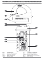
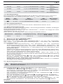
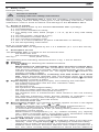
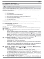
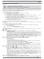
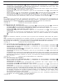
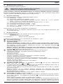
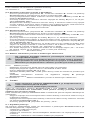
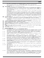
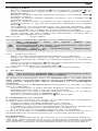
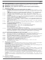
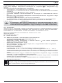
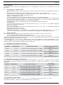
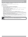
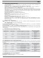
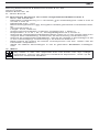
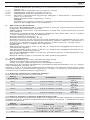
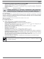
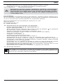
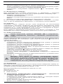
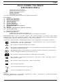
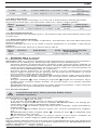
Bild 2: Gleichspannungsmessung
Fig. 2: Direct voltage measurement
Fig. 2: Mesure de tension continue
Fig. 2: Medición de tension contínua
Obr.2: Měření stejnosměrného napětí
σχήμα 2: μέτρηση DC-τάσης
2. bra: Egyenfeszültség mérés
ill. 2: Misura tensione continua
Fig. 2: Meten van gelijkspanning
Rys.2: Pomiar napięcia stałego
Imaginea 2: Măsurarea tensiunii continue
Рис. 2. Измерение напряжения
постоянного тока
Fig. 2: Likspänningsmätning
Resim 2: Doğru Gerilim Ölçümü
Bild 3: Wechselspannungsmessung
Fig. 3: Alternating voltage measurement
Fig. 3: Mesure de tension alternative
Fig. 3: Medición de tensión alterna
Obr.3: Měření střídavého napětí
σχήμα 3: μέτρηση AC-τάσης
3. bra: V ltakozó feszültség mérés
ill. 3: Misura tensione alternata
Fig. 3: Meten van wisselspanning
Rys.3: Pomiar napięcia przemiennego
Imaginea 3: Măsurarea tensiunii alternative
Рис. 3 Измерение напряжения
переменного тока
Fig. 3: Växelspänningsmätning
Resim 3: Alternatif Gerilim Ölçümü
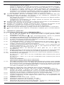
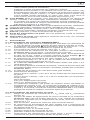
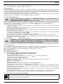
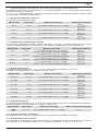
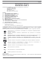
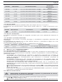
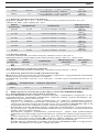
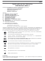
Bild 4: Widerstandsmessung
Fig. 4: Resistance measurement
Fig. 4: Mesure de résistance
Fig. 4: Medición de resistencia
Obr.4: Měření odporu
σχήμα 4: Μέτρηση αντίστασης
4. bra: Váltakozó áram mérés
ill. 4: Misura di resistenza
Fig. 4: Weerstandsmeting
Rys.4: Pomiar rezystancji
Imaginea 4: Măsurarea rezistenţei
Рис. 4. Измерение сопротивления
Fig. 4: Resistansmätning
Resim 4: Direnç Ölçümü

11/ 2008
BENNING MM 4
D F E H I S
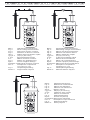
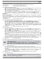
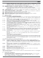
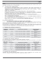
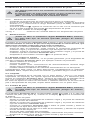
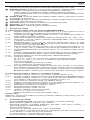
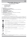
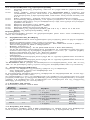
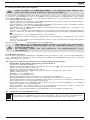
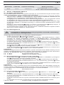
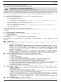
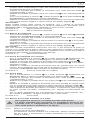
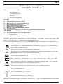
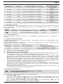
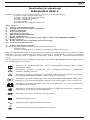
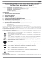
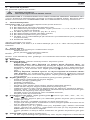
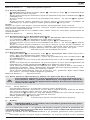
Bild 6: Diodenprüfung
Fig. 6: Diode Testing
Fig. 6: Contrôle de diodes
Fig. 6: Verificación de diodos
Obr.6: Měření diod
σχήμα 6: Έλεγχος διόδου
6. bra: Dióda vizsgálatra
ill. 6: Prova diodi
Fig. 6: Diodecontrole
Rys.6: Pomiar diody
Imaginea 6: Măsurarea diodelor
Рис. 6. Проверка диодов
Fig. 6: Diod-test
Resim 6: Diyot Kontrolü
Bild 5: Durchgangsprüfung mit Summer
Fig. 5: Continuity Testing with buzzer
Fig. 5: Contrôle de continuité avec ronfleur
Fig. 5: Control de continuidad con vibrador
Obr.5: Zkouška průchodu bzučákem
σχήμα 5: Έλεγχος συνέχειας με ηχητικό σήμα
5. bra: A kiválasztott mérési tartomány
ill. 5: Prova di continuità con cicalino
Fig. 5: Doorgangstest met akoestisch signaal
Rys.5: Sprawdzenie ciągłości obwodu
Imaginea 5: Măsurarea continuităţii cu buzzer
Рис. 5. Контроль прохождения тока с зуммером
Fig. 5: Genomgångstest med summer
Resim 5: Akustik Uyarıcı ile Süreklilik Ölçümü

11/ 2008
BENNING MM 4
D F E H I S
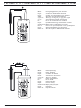
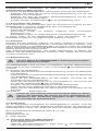
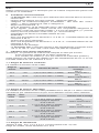
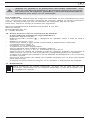
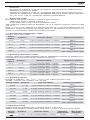
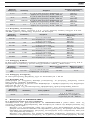
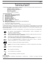
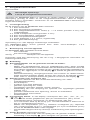
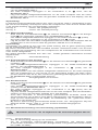
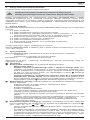
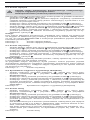
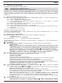
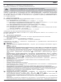
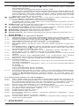
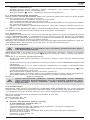
Bild 8: Batteriewechsel
Fig. 8: Battery replacement
Fig. 8: Remplacement de la pile
Fig. 8: Cambio de pila
Obr.8: Výměna baterií
σχήμα 8: Αντικατάσταση μπαταριών
8. bra: Telepcsere
ill. 8: Sostituzione batterie
Fig. 8: Vervanging van de batterijen
Rys.8: Wymiana baterii
Imaginea 8: Schimbarea bateriei
Рис. 8. Замена батарейки
Fig. 8: Batteribyte
Resim 8: Batarya Değişimi
Bild 7: Wechselstrommessung mit
Strom zangen aufsatz
Fig. 7: AC current current measurement with current
transducer
Fig. 7: Mesure de courant alternatif avec la pince
électrique rapportée
Fig. 7: Medición de corriente alterna con el
amperímetro de pinza
Fig. 7: Meten van wisselstroom met stroomtang
Obr.7: Měření střídavého proudu s klešťovým
proudovým nástavcem
σχήμα 7: Τρέχουσα μέτρηση AC με την
αμπεροτσιμπίδα
7. bra: Árammérés lakatfogó fejjel
ill. 7: Misura di corrente alternata con pinza
Rys.7: Pomiar prądu przemiennego przetwornikiem
cęgowym
Imaginea 7: Măsurarea curentului alternativ cu cleştele de
curent ataşabil
Рис. 7. Измерение переменного тока с
насадкой токового клещевого захвата
Fig. 7: Växelströmsmätning med strömtångtillsats
Resim 7: Akım Pensesi (Pensemetre) ile Alternatif
Akım Ölçümü

11/ 2008
BENNING MM 4
1
D
Bedienungsanleitung
BENNING MM 4
Digital-Multimeter mit Stromzangenaufsatz zur
- Wechselstrommessung
- Wechselspannungsmessung
- Gleichspannungsmessung
- Widerstandsmessung
- Diodenprüfung
- Durchgangsprüfung
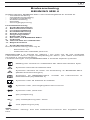
Inhaltsverzeichnis
1. Benutzerhinweise
2. Sicherheitshinweise
3. Lieferumfang
4. Gerätebeschreibung
5. Allgemeine Angaben
6. Umgebungsbedingungen
7. Elektrische Angaben
8. Messen mit dem BENNING MM 4
9. Instandhaltung
10. Technische Daten des Messzubehörs
11. Umweltschutz
1. Benutzerhinweise
Diese Bedienungsanleitung richtet sich an
- Elektrofachkräfte und
- elektrotechnisch unterwiesene Personen
Das BENNING MM 4 ist zur Messung in trockener Umgebung vorgesehen und
darf nicht in Stromkreisen mit einer höheren Nennspannung als 600 V einge-
setzt werden (Näheres hierzu in Abschnitt 6. „Umgebungsbedinungen“).
In der Bedienungsanleitung und auf dem BENNING MM 4 werden folgende
Symbole verwendet:
Anlegen um GEFÄHRLICH AKTIVE Leiter oder Abnehmen von
diesen ist zugelassen.
Dieses Symbol weist auf elektrische Gefahr hin.
Dieses Symbol weist auf Gefährdungen beim Gebrauch des
BENNING MM 4 hin. (Dokumentation beachten!)
Dieses Symbol auf dem BENNING MM 4 bedeutet, dass das Gerät
schutzisoliert (Schutzklasse II) ausgeführt ist.
Dieses Symbol erscheint in der Anzeige für eine entladene
Batterie.
Dieses Symbol kennzeichnet den Bereich “Durchgangsprüfung”.
Der Summer dient der akustischen Er geb nis aus gabe.
Dieses Symbol kennzeichnet den Bereich „Diodenprüfung“.
(DC) Gleichspannung.
(AC) Wechsel- Spannung oder Strom.
Masse (Spannung gegen Erde).
Hinweis
Nach Entfernen des Klebeschildes „Warnung...“ (auf dem Batteriedeckel) er-
scheint der englische Text!

11/ 2008
BENNING MM 4
2
D
2. Sicherheitshinweise
Beispiel für Sicherheitshinweis:
Elektrische Gefahr!
Beachten Sie die Sicher heits hinweise!
Bevor Sie das BENNING MM 4 benutzen, lesen Sie bitte die Bedienungsanleitung
sorgfältig. Beachten Sie die Sicherheitshinweise in der Bedienungsanleitung.
Damit schützen Sie sich vor Unfällen und das BENNING MM 4 vor Schaden.
3. Lieferumfang
Zum Lieferumfang des BENNING MM 4 gehören:
3.1 ein Stück Multimeter,
3.2 ein Stück Stromzangenaufsatz,
3.3 ein Stück Sicherheitsmessleitung, schwarz (L = 1,4 m, Spitze Ø 4 mm)
mit Schutzkappen,
3.4 zwei Stück Messspitzen, rot (Spitze Ø 4 mm),
3.5 ein Stück isolierte Krokodilklemme,
3.6 eine Stück Kompakt-Schutztasche,
3.7 zwei Stück 1,5-V-Micro-Batterien (zur Erstbestückung im Multimeter
eingebaut),
3.8 die Bedienungsanleitung.
Hinweis auf Verschleißteile:
Das BENNING MM 4 wird von zwei 1,5-V-Micro-Batterien (2 x 1,5-V-IEC LR 03)
gespeist.
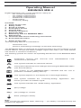
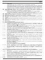
4. Gerätebeschreibung
Das BENNING MM 4 besteht aus zwei Funktionseinheiten,
- dem Multimeter und
- dem Stromzangenaufsatz.
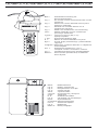
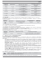
siehe Bild 1: Gerätefrontseite
Die in Bild 1 angegebenen Anzeige- und Bedienelemente werden wie folgt
bezeichnet:
1 Gehäuse
2 Schiebeschalter, dient zur Wahl der gewünschten Funktionen.
- Aus (OFF)
- Wechselspannungsmessung (AC) und Gleichspannungsmessung
(DC), diese Funktionen wechseln auf Tastendruck der blau gekenn-
zeichneten Funktionstaste einander ab. Bei längerem Druck (2 s)
Wechselstrommessung, usw. Die Digitalanzeige 3 zeigt die aktuelle
Funktion.
- Widerstandsmessung, Durchgangsprüfung mit Summer und
Diodenprüfung, diese Funktionen wechseln auf Tastendruck der blau
gekennzeichneten Funktionstaste einander ab. Die Digitalanzeige 3
zeigt die aktuelle Funktion.
3 Digitalanzeige (Flüssigkristallprinzip), angezeigt werden
- der Messwert mit der max. Anzeige 4200,
- die Polaritätsanzeige,
- der Dezimalpunkt,
- das Symbol für die entladene Batterie,
- die gewählte Spannungsart (Gleichspannung/ Wechselspannung),
- der festgehaltene Messwert (Holdfunktion),
- das Anzeigen einer Abweichung von einem gespeicherten Messwert (REL),
- der gewählte Messbereich durch Anzeige der erweiterten/ nicht erwei-
terten Maßeinheiten von Spannung, Strom und Widerstand,
- die gewählte Durchgangsprüfung mit Summer,
- die gewählte Diodenprüfung.
4 Funktionstaste blau, in der Digitalanzeige 3 erscheinen dazu „DC“; „AC“;
„Ω“; „V“; „ “ oder „ “
- zur Wahl zwischen Gleichspannungsmessung (DC) und
Wechselspannungsmessung (AC) bzw.
- Widerstandsmessung, Durchgangs- und Diodenprüfung.
- oder nach 2 s Tastenbetätigung (in Schiebeschalter-Stellung AC V/
DC V) Wechselstrom (Amp).
- Messungen der Temperatur (°C, °F), Rel. Feuchte (%), Kapazität (µF),
Kohlenmonoxid (ppm), Windgeschwindigkeit (m/s), Beleuchtungsstärke
(k lux) sind mit dem BENNING MM 4 nicht möglich.
- erneute 2 s Tastenbetätigung führt zurück zur Spannungsmessung
5 HOLD/ REL-Taste (Haltefunktion),
- erster Tastendruck führt zum Halten des angezeigten Messwertes
(angezeigt durch „Hold“ in der Digitalanzeige 3, keine Aktualisierung

11/ 2008
BENNING MM 4
3
D
des Messwertes),
- erneuter Tastendruck führt zu fortlaufender Messung.
- Taste 2 s gedrückt führt in die Relativwert-Funktion. Der anliegende
Messwert wird gespeichert und die Differenz (Offset) zum nächst höhe-
ren oder niedrigeren Messwert angezeigt. Durch erneutes Drücken
kann ein neuer Basiswert gespeichert werden. Zurückschaltung in den
Normalmodus durch längere (2 s) Tastenbetätigung.
6 RANGE-Taste (Bereichstaste), zur manuellen Wahl der Spannungs-,
Strom- bzw. der Widerstandsmessbereiche, (angezeigt durch „RANGE“ in
der Digitalanzeige)
- die Messbereiche wechseln auf kurzen Tastendruck,
- automatische Bereichswahl wird durch längeren Tastendruck (Zeit
größer 2 Sekunden) eingestellt.
7
COM-Buchse, gemeinsame Buchse für Spannungs-, Widerstandsmessungen,
Durchgangs- und Diodenprüfung, schwarz markiert.
8 V-Ω-Buchse (positive), gemeinsame Buchse für Spannungs-,
Widerstandsmessungen, Durchgangs- und Diodenprüfung, rot markiert.
9 Öffnungshebel, zum Öffnen und Schließen der Stromzange.
J Stromzangenwulst, schützt vor Leiterberührung.
K Messzange, zum Umfassen des einadrigen wechselstromdurchflossenen
Leiters.
5. Allgemeine Angaben
5.1 Allgemeine Angaben zum BENNING MM 4
5.1.1 Die Digitalanzeige ist als 3¾-stellige Flüssigkristallanzeige mit 11 mm
Schrifthöhe mit Dezimalpunkt ausgeführt. Der größte Anzeigewert ist 4200.
5.1.2 Die Polaritätsanzeige 3 wirkt automatisch. Es wird nur eine Polung
entgegen der Buchsendefinition mit „-“ angezeigt.
5.1.3 Die Bereichsüberschreitung wird mit „OL“ oder „-OL“ angezeigt.
5.1.4 Die Messrate der Ziffernanzeige des BENNING MM 4 beträgt nominal
ca. 2 Messungen pro Sekunde.
5.1.5 Das BENNING MM 4 schaltet nach ca. 30 min. selbstätig ab. Es schal-
tet wieder ein, wenn die RANGE-Taste 6 betätigt wird. Ein Summerton
warnt vor selbsttätiger Abschaltung.
5.1.6 Temperaturkoeffizient des Messwertes: 0,15 × (angegebene
Messgenauigkeit)/ °C < 18 °C oder > 28 °C, bezogen auf den Wert bei
der Referenztemperatur 23 °C.
5.1.7 Das BENNING MM 4 wird durch zwei Stück 1,5-V-Batterien gespeist
(IEC LR03/ „Micro“).
5.1.8 Wenn die Batteriespannung unter die vorgesehene Arbeitsspannung
des BENNING MM 4 sinkt, dann erscheint in der Anzeige ein
Batteriesymbol.
5.1.9 Die Lebensdauer der Batterien beträgt etwa 800 Stunden
(Alkalibatterie).
5.1.10 Geräteabmessungen:
(L x B x H) = 145 x 52 x 34 mm Multimeter ohne Stromzangenaufsatz,
(L x B x H) = 225 x 77 x 35 mm Multimeter mit Stromzangenaufsatz
Gerätegewicht:
100 g ohne Stromzangenaufsatz
230 g mit Stromzangenaufsatz
5.1.11 Die Sicherheitsmessleitung und die Messspitzen sind in 4 mm-
Stecktechnik ausgeführt. Die mitgelieferte Sicherheitsmessleitung und
die Messspitzen sind ausdrücklich für die Nennspannung und dem
Nennstrom des BENNING MM 4 geeignet. Die Messspitzen können
durch Schutzkappen geschützt werden.
5.2 Allgemeine Angaben zum Stromzangenaufsatz
5.2.1 Strommessbereich: von 0,1 A
eff
bis 300 A
eff
(Direktanzeige, A)
5.2.2 Ausgangsspannung: Der Stromzangenaufsatz des BENNING MM 4
gibt eine Wechselspannung von 1 mV ab, wenn der von dem
Stromzangenaufsatz umschlossene einadrige Leiter einen
Wechselstrom von 0,1 A führt.
5.2.3 Sensorart: Induktionsspule für den Wechselstrom.
5.2.4 Temperaturkoeffizient des Messwertes: 0,15 x (angegebene Mess-
genauigkeit)/ °C bezogen auf den Wert bei der Referenztemperatur 23 °C.
5.2.5 Max. Scheinwiderstand am Ausgang: 120 Ω
5.2.6 Größte Zangenöffnung: 30 mm
5.2.7 Größter Leiterdurchmesser: 29 mm
5.2.8 Abmessungen des Stromzangenaufsatzes: (L x B x H) = 102 x 77 x 35 mm
Gewicht des Stromzangenaufsatzes: 130 g
Hinweis:
Der Stomzangenaufsatz darf nur zur Messung verwendet werden, wenn dieser
auf dem Multimeter aufgesteckt ist.

11/ 2008
BENNING MM 4
4
D
6. Umgebungsbedingungen
- Das BENNING MM 4 ist nur für Messungen in trockener Umgebung vorge-
sehen,
- Barometrische Höhe bei Messungen: Maximal 2000 m,
- Überspannungskategorie/ Aufstellungskategorie: IEC 664/ IEC 1010-1
(2001) → 300 V Kategorie III; 600 V Kategorie ll.
- Verschmutzungsgrad: 2,
- Schutzart: IP 30 (DIN VDE 0470-1 IEC/ EN 60529)
3 - erste Kennziffer: Schutz gegen Zugang zu gefährlichen Teilen und
Schutz gegen feste Fremdkörper, > 2,5 mm Durchmesser
0 - zweite Kennziffer: Kein Wasserschutz,
- Arbeitstemperatur und relative Luftfeuchte:
Multimeter:
Bei Arbeitstemperatur von 0 °C bis 50 °C: relative Luftfeuchte kleiner 80 %,
Stromzangenaufsatz:
Bei Arbeitstemperatur von 0 °C bis 45 °C: relative Luftfeuchte kleiner 75 %,
- Lagerungstemperatur:
Das BENNING MM 4 kann bei Temperaturen von - 20 °C bis + 60 °C gela-
gert werden. Dabei sind die Batterien aus dem Gerät heraus zu nehmen.
7. Elektrische Angaben
Bemerkung: Die Messgenauigkeit wird angegeben als Summe aus
- einem relativen Anteil des Messwertes und
- einer Anzahl von Digit (d.h., Zahlenschritte der letzten Stelle).
Diese Messgenauigkeit gilt bei der Temperatur von 23 °C und einer relativen
Luftfeuchtigkeit kleiner 75 %.
Die Abschnitte 7.1 bis 7.5 beziehen sich auf den Anschluss des Multimeters an
die Messkreise (Stromzangenaufsatz entfernt). Der Abschnitt 7.6 bezieht sich
auf die Kombination von Multimeter und aufgestecktem Stromzangenaufsatz.
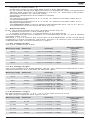
7.1 Gleichspannungsbereiche
Der Eingangswiderstand beträgt 9 MΩ.
Messbereich Auflösung Messgenauigkeit Überlastschutz
4,2 V 1 mV ± (0,5 % des Messwertes + 2 Digit)
600 V
eff
600 V Gleichspannung
42 V 10 mV ± (0,5 % des Messwertes + 2 Digit)
600 V
eff
600 V Gleichspannung
420 V 100 mV ± (0,5 % des Messwertes + 2 Digit)
600 V
eff
600 V Gleichspannung
600 V 1 V ± (0,5 % des Messwertes + 2 Digit)
600 V
eff
600 V Gleichspannung
7.2 Wechselspannungsbereiche
Der Eingangswiderstand beträgt 9 MΩ parallel 100 pF. Der Messwert wird durch
Mittelwertgleichrichtung gewonnen und als Effektivwert angezeigt.
Messbereich Auflösung Messgenauigkeit Überlastschutz
4,2 V 1 mV
± (1,5 % des Messwertes + 5 Digit)
im Frequenzbereich 40 Hz - 300 Hz
600 V
eff
600 V Gleichspannung
42 V 10 mV
± (1,5 % des Messwertes + 5 Digit)
im Frequenzbereich 40 Hz - 500 Hz
600 V
eff
600 V Gleichspannung
420 V 100 mV
± (1,5 % des Messwertes + 5 Digit)
im Frequenzbereich 40 Hz - 500 Hz
600 V
eff
600 V Gleichspannung
600 V 1 V
± (1,5 % des Messwertes + 5 Digit)
im Frequenzbereich 40 Hz - 300 Hz
600 V
eff
600 V Gleichspannung
7.3 Widerstandsbereiche
Leerlaufspannung: ca. 1,3 V - 3,3 V, max. Prüfstrom 2,5 mA.
42 MΩ -Bereich, Einschwingzeit ca. 20 s
Messbereich Auflösung Messgenauigkeit Überlastschutz
420 Ω 0,1 Ω ± (1,2 % des Messwertes + 8 Digit)
600 V
eff
600 V Gleichspannung
4,2 kΩ 1 Ω ± (0,9 % des Messwertes + 4 Digit)
600 V
eff
600 V Gleichspannung
42 kΩ 10 Ω ± (0,9 % des Messwertes + 4 Digit)
600 V
eff
600 V Gleichspannung

11/ 2008
BENNING MM 4
5
D
420 kΩ 100 Ω ± (1,2 % des Messwertes + 4 Digit)
600 V
eff
600 V Gleichspannung
4,2 MΩ 1 kΩ ± (1,2 % des Messwertes + 4 Digit)
600 V
eff
600 V Gleichspannung
42 MΩ 10 kΩ ± (3,0 % des Messwertes + 8 Digit)
600 V
eff
600 V Gleichspannung
7.4 Diodenprüfung
Die angegebene Messgenauigkeit gilt im Bereich zwischen 0,4 V und 0,8 V.
Überlastschutz bei Diodenprüfungen: 600 V
eff
/ 600 V Gleichspannung.
Mess-
bereich
Auf-
lösung
Mess-
genauigkeit
Max.
Messstrom
Max. Leerlauf-
spannung
0,1 mV
± (1,5 % des Messwertes + 5 Digit)
1,5 mA
3,3 V
7.5 Durchgangsprüfung
Der eingebaute Summer ertönt bei einem Widerstand kleiner 50 Ω.
7.6 Wechselstrombereiche
(Multimeter mit Stromzangenaufsatz, Stromzangenaufsatz umfasst einadrigen
wechselstromführenden Leiter).
Messgenauigkeit beträgt ± (% des Messwertes + Anzahl von Digit) bei einer
Temperatur von 23 °C ± 5 °C.
Max. Strom des beiliegenden Stromzangenaufsatzes 300 A!
Messbereich Auflösung Ausgangsspannung
Messgenauigkeit im Frequenzbereich
40 Hz - 300 Hz
300 A 0,1 A 1 mV/ 0,1 A
± (1,5 % des Messwertes + 5 Digit)
8. Messen mit dem BENNING MM 4
8.1 Vorbereiten der Messungen
Benutzen und lagern Sie das BENNING MM 4 nur bei den angegebe-
nen Lager- und Arbeitstemperaturbedingungen, vermeiden Sie dauernde
Sonneneinstrahlung.
- Angaben von Nennspannung und Nennstrom auf der schwarzen
Sicherheitsmessleitung und den roten Messspitzen überprüfen. Die
zum Lieferumfang gehörende schwarze Sicherheitsmessleitung und die
roten Messspitzen entsprechen in Nennspannung und Nennstrom dem
BENNING MM 4.
- Isolation der Sicherheitsmessleitung und der roten Messspitzen überprüfen.
Wenn die Isolation beschädigt ist, dann die Sicherheitsmessleitung und/
oder die roten Messspitzen sofort aussondern!
- Sicherheitsmessleitung auf Durchgang prüfen. Wenn der Leiter in der
Sicherheitsmessleitung unterbrochen ist, dann ist die Sicherheitsmessleitung
sofort auszusondern.
- Bevor am Schiebeschalter 2 oder der Funktionstaste 4 eine andere
Funktion gewählt wird, müssen die Sicherheitsmessleitung und die rote
Messspitze von der Messstelle getrennt werden.
- Starke Störquellen in der Nähe des BENNING MM 4 können zu instabiler
Anzeige und zu Messfehlern führen.
8.2 Spannungsmessung
Maximale Spannung gegen Erd po ten tial beachten!
Elektrische Gefahr!
Die höchste Spannung, die an den Buchsen des Multimeters,
- COM-Buchse 7, schwarz markiert,
- V-Ω-Buchse (positive) 8 für Spannungs- und Widerstandsmessungen,
Durchgangs- und Diodenprüfung, rot markiert, des BENNING MM 4 gegen-
über Erdpotential liegen darf, beträgt 600 V.
- Die schwarze Sicherheitsmessleitung mit der COM-Buchse 7, schwarz
gekennzeichnet, kontaktieren.
- Die rote Messspitze mit der V-Ω-Buchse
8
, rot gekennzeichnet, kontaktieren.
- Mit dem Schiebeschalter 2, der Funktionstaste 4 und der RANGE-Taste
6 des BENNING MM 4 den gewünschten Bereich wählen.
- Die schwarze Sicherheitsmessleitung und die rote Messspitze mit den
Messpunkten kontaktieren, den Messwert an der Digitalanzeige
3
ablesen.
Hinweis:
In kleinen Spannungsmessbereichen unterbleibt bei offenen Sicherheitsmessleitungen

11/ 2008
BENNING MM 4
6
D
die Null-Volt-Anzeige durch Einstreuungen. Überzeugen Sie sich durch Kurzschluss
der Messspitzen davon, dass das BENNING MM 4 funktionsfähig ist.
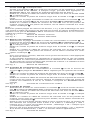
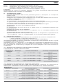
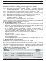
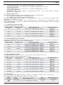
siehe Bild 2: Gleichspannungsmessung
siehe Bild 3: Wechselspannungsmessung
8.3 Widerstandsmessung
- Mit dem Schiebeschalter 2, der Funktionstaste 4 und der RANGE-Taste
6 am BENNING MM 4 den gewünschten Bereich wählen.
- Die schwarze Sicherheitsmessleitung mit der COM-Buchse 7, schwarz
gekennzeichnet, kontaktieren.
- Die rote Messspitze mit der V-Ω-Buchse
8
, rot gekennzeichnet, kontaktieren.
- Die schwarze Sicherheitsmessleitung und die rote Messspitze mit den
Messpunkten kontaktieren, den Messwert an der Digitalanzeige
3
ablesen.
Hinweis:
Stellen Sie für eine richtige Messung sicher, dass an der Messstelle keine
Spannung anliegt.
Das Messergebnis bei kleinen Widerständen kann verbessert werden,
indem der Widerstand der Sicherheitsmessleitung zuvor mit Kurzschluss der
Messspitzen gemessen wird und der so gewonnene Widerstand vom Ergebnis
subtrahiert wird.
siehe Bild 4: Widerstandsmessung
8.4 Durchgangsprüfung mit Summer
-
Mit dem Schiebeschalter 2 und der Funktionstaste 4 den mit dem Summer-
Symbol „ “ gekennzeichneten Bereich am BENNING MM 4 wählen.
- Die schwarze Sicherheitsmessleitung mit der COM-Buchse
7
kontaktieren.
- Die rote Messspitze mit der V-Ω-Buchse
8
, rot gekennzeichnet, kontaktieren.
- Kontaktieren Sie die schwarze Sicherheitsmessleitung und die rote
Messspitze mit den Messpunkten. Wenn der Widerstand zwischen den
Messpunkten 50 Ω unterschreitet, dann ertönt der im BENNING MM 4
eingebaute Summer.
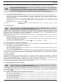
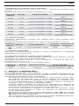
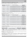
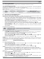
siehe Bild 5: Durchgangsprüfung mit Summer
8.5 Diodenprüfung
- Mit dem Schiebeschalter 2 und der Funktionstaste 4 den mit dem Dioden-
Symbol „ “ gekennzeichneten Bereich am BENNING MM 4 wählen.
- Die schwarze Sicherheitsmessleitung mit der COM-Buchse 7, schwarz
gekennzeichnet, kontaktieren.
- Die rote Messspitze mit der V-Ω-Buchse
8
, rot gekennzeichnet, kontaktieren.
- Die schwarze Sicherheitsmessleitung und die rote Messspitze mit den
Diodenanschlüssen kontaktieren, den Messwert an der Digitalanzeige 3
ablesen.
- Für in Flussrichtung angelegte Si-Diode wird die Flussspannung von 0,500 V bis
0,900 V angezeigt. Die Anzeige „000“ deutet auf einen Kurzschluss in der Diode
hin, die Anzeige „OL“ deutet auf eine Unterbrechung in der Diode hin.
- Für eine in Sperrrichtung angelegte Diode wird „OL“ angezeigt. Wenn die
Diode fehlerhaft ist, dann werden „000“ oder andere Werte angezeigt.
siehe Bild 6: Diodenprüfung
8.6 Wechselstrommessung mit dem Stromzangenaufsatz
Keine Spannung an die Ausgangskontakte des Stromzangen-
aufsatzes legen!
Der Stromzangenaufsatz darf nur in Verbindung mit dem
Multimeter einen stromdurchflossenen Leiter umfassen!
Max. Strom des beiliegenden Stromzangenaufsatzes 300 A!
8.6.2 Strommessung
- Den Stromzangenaufsatz fest auf das Multimeter kontaktieren.
- Am Multimeter die Spannungsmessung einschalten. Die blaue Taste 2 s
drücken und mit der RANGE-Taste den gewünschten Bereich wählen. (Amp
CLAMP)
- Öffnungshebel 9 betätigen, einadrigen Leiter mit der Zange, des
Stromzangenaufsatzes der den zu messenden Strom führt, umfassen.
- Die Digitalanzeige 3 ablesen.
siehe Bild 7: Wechselstrommessung mit Stromzangenaufsatz
9. Instandhaltung
Vor dem Öffnen das BENNING MM 4 unbedingt spannungsfrei
machen! Elektrische Gefahr!
Die Arbeit am geöffneten BENNING MM 4 unter Spannung ist ausschließlich

11/ 2008
BENNING MM 4
7
D
Elektrofachkräften vorbehalten, die dabei besondere Maßnahmen zur
Unfallverhütung treffen müssen.
So machen Sie das BENNING MM 4 spannungsfrei, bevor Sie das Gerät öffnen:
- Entfernen Sie zuerst die schwarze Sicherheitsmessleitung und die rote
Messspitze vom Messobjekt.
- Entfernen Sie dann die schwarze Sicherheitsmessleitung und die rote
Messspitze vom BENNING MM 4.
- Schalten Sie den Schiebeschalter 2 in die Schaltstellung „OFF“.
9.1 Sicherstellen des Gerätes
Unter bestimmten Voraussetzungen kann die Sicherheit im Umgang mit dem
BENNING MM 4 nicht mehr gewährleistet sein; zum Beispiel bei:
- Sichtbaren Schäden am Gerät,
- Fehlern bei Messungen,
- Erkennbaren Folgen von längerer Lagerung unter unzulässigen
Bedingungen und
- Erkennbaren Folgen von außerordentlicher Transportbeanspruchung.
In diesen Fällen ist das BENNING MM 4 sofort abzuschalten, von der
Messstelle zu entfernen und gegen erneute Nutzung zu sichern.
9.2 Reinigung
Reinigen Sie das Gehäuse äußerlich mit einem sauberen trockenen Tuch
(Ausnahme spezielle Reinigungstücher). Verwenden Sie keine Lösungs- und/
oder Scheuermittel, um das BENNING MM 4 zu reinigen. Achten Sie unbedingt
darauf, dass das Batteriefach und die Batteriekontakte nicht durch auslaufendes
Batterie-Elektrolyt verunreinigt werden.
Falls Elektrolytverunreinigungen oder weiße Ablagerungen im Bereich der
Batterie oder des Batteriegehäuses vorhanden sind, reinigen Sie auch diese
mit einen trockenem Tuch.
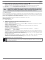
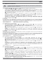
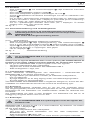
9.3 Batteriewechsel
Vor dem Öffnen das BENNING MM 4 unbedingt spannungsfrei
machen! Elektrische Gefahr!
Das BENNING MM 4 wird von zwei 1,5-V-Batterien gespeist. Batteriewechsel
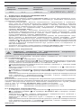
(siehe Bild 8) ist dann erforderlich, wenn in der Anzeige 3 das Batteriesymbol
erscheint.
So wechseln Sie die Batterien:
- Entfernen Sie die schwarze Sicherheitsmessleitung und die rote Messspitze
vom Messkreis.
- Entfernen Sie die schwarze Sicherheitsmessleitung und die rote Messspitze
vom BENNING MM 4.
- Legen Sie das BENNING MM 4 auf das Frontteil, und lösen Sie die
Schraube aus dem Gehäuseboden.
- Heben Sie den Gehäuseboden an der Buchsenseite an, und nehmen Sie
ihn nahe der Digitalanzeige 3 vom Frontteil ab.
- Entfernen Sie die entladenen Batterien aus dem Batteriehalter.
- Legen Sie die neuen Batterien polrichtig in den Batteriehalter.
- Rasten Sie den Gehäuseboden an das Frontteil an und montieren Sie die
Schraube.
siehe Bild 8: Batteriewechsel
Leisten Sie Ihren Beitrag zum Umweltschutz! Batterien dürfen
nicht in den Hausmüll. Sie können bei einer Sammelstelle für
Altbatterien bzw. Sondermüll abgegeben werden. Informieren
Sie sich bitte bei Ihrer Kommune.
9.4 Kalibrierung
Um die angegebenen Genauigkeiten der Messergebnisse zu erhalten, muss das
Gerät regelmäßig durch unseren Werksservice kalibriert werden. Wir empfehlen ein
Kalibrierintervall von einem Jahr. Senden Sie hierzu das Gerät an folgende Adresse:
Benning Elektrotechnik & Elektronik GmbH & Co. KG
Service Center
Robert-Bosch-Str. 20
D - 46397 Bocholt
10. Technische Daten des Messzubehörs
4 mm Sicherheitsmessleitung ATL 2
- Norm: EN 61010-031,
- Maximale Bemessungsspannung gegen Erde ( ) und Messkategorie:
1000 V CAT III, 600 V CAT IV,

11/ 2008
BENNING MM 4
8
D
- Maximaler Bemessungsstrom: 10 A,
- Schutzklasse II (
), durchgängige doppelte oder verstärkte Isolierung,
- Verschmutzungsgrad: 2,
- Länge: 1,4 m, AWG 18,
- Umgebungsbedingungen:
Barometrische Höhe bei Messungen: Maximal 2000 m,
Temperatur: 0°C bis + 50 °C, Feuchte 50 % bis 80 %
- Verwenden Sie die Messleitungen nur im einwandfreien Zustand und
entsprechend dieser Anleitung, da ansonsten der vorgesehene Schutz
beeinträchtigt sein kann.
- Sondern Sie die Messleitung aus, wenn die Isolierung beschädigt ist oder
eine Unterbrechung in Leitung/ Stecker vorliegt.
- Berühren Sie die Messleitung nicht an den blanken Kontaktspitzen. Fassen
Sie nur den Handbereich an!
- Stecken Sie die abgewinkelten Anschlüsse in das Prüf- oder Messgerät.
11. Umweltschutz
Bitte führen Sie das Gerät am Ende seiner Lebensdauer den zur
Verfügung ste hen den Rückgabe- und Sammelsystemen zu.

11/ 2008
BENNING MM 4
9
Operating Manual
BENNING MM 4
Digital Multimeter with current transducer clamp for:
- AC current measurement
- AC-voltage measurement
- DC-voltage measurement
- Resistance measurement
- Diode testing
- Continuity testing
Contents:
1. Notes for the user
2. Safety notes
3. Scope of supply
4. Description of unit
5. General data
6. Ambient conditions
7. Electrical data
8. Measuring with the BENNING MM 4
9. Maintenance
10. Technical data of the measuring accessories
11. Environmental notice
1. Notes for the user
This Operating Manual is intended for:
- electricians and
- persons possessing knowledge of electrical technology.
The BENNING MM 4 is designed for measurements in dry surroundings. It must
not be used in circuits with rated voltages higher than 600 V (for more details,
see section 6 “Ambient conditions”).
The following symbols are used in the Operating Manual and on the BENNING MM 4
itself:
Application around and removal from HAZARDOUS LIVE
conductors is permitted.
This symbol indicates an electrical hazard.
This symbol indicates sources of danger when using the BENNING MM 4
(see documentation).
This symbol on the BENNING MM 4 indicates that the unit is
protection insulated (safety class II).
This symbol appears in the display for a discharged battery.
This symbol indicates the “continuity-testing” application. The
buzzer provides an audible signal.
This symbol indicates the “diode-testing” application.
(DC)-voltage.
(AC)-voltage or current.
Earth (voltage to earth).
Note
After unmark the adhesive label „Warnung...“ (on battery compartment lid) the
English text appears.

11/ 2008
BENNING MM 4
10
2. Safety notes
Example safety note:
Electrical hazard!
Comply with the safety instructions!
Before using the BENNING MM 4 read the operating instructions carefully.
Always comply with the safety notes given in the operating instructions. This is
essential in order to avoid accidents and damage to the BENNING MM 4.
3. Scope of supply
The following items make up the standard BENNING MM 4 package:
3.1 one Multimeter,
3.2 one current transducer clamp,
3.3 one safety test lead, black (length = 1.4 m, tip Ø 4 mm) with safety
caps,
3.4 two test probes, red (tip Ø 4 mm),
3.5 one insulated crocodile clamp,
3.6 one compact protection case,
3.7 two 1.5 V micro-batteries (in place in Multimeter on delivery),
3.8 the set Operating Instructions.
Note on consumable parts:
The BENNING MM 4 is supplied by two 1.5 V batteries (2 x 1,5-V-IEC LR 03).
4. Description of unit
The BENNING MM 4 consists of two functional units:
- the Multimeter and
- the current transducer clamp.
See fig.1: Front panel of unit
The operating and indicating elements shown in fig. 1 are as follows:
1 Housing
2 Sliding switch for selecting the desired functions.
- Aus (OFF)
- Measurement of alternating voltage (AC) and direct voltage (DC).
These functions alternate with one-another when the function button
with the blue marking is pressed. When pressed longer (2 sec.) meas-
urement of alternating current, etc. The digital display 3 indicates the
function currently in effect.
- Resistance measurement, continuity test with buzzer and diode
test. These functions alternate with one-another when the function
button with the blue marking is pressed. The digital display 3 indicates
the function currently in effect.
3 Digital display (liquid-crystal principle). The following are indicated:
- the measurement value with the max. indication 4200,
- the polarity indication,
- the decimal point,
- the symbol for discharged battery,
- the type of voltage selected (DC or AC voltage),
- the measurement value held (hold function),
- the deviation from a measurement value stored in the unit memory
(REL ∆),
- the selected measuring range through display of extended / non-
extended measuring units of voltage, current and resistance,
- the selected continuity test with buzzer,
- the selected diode test.
4 Blue function button: the following symbols appear for this in the digital
display 3: “DC”; “AC”; “Ω”, “V”; „ “ or „ “
- Selection between DC-voltage and AC-voltage measurement or
- resistance measurement, continuity and diode test,
- or when button pressed for 2 sec. (in sliding-switch position ACV / DCV)
alternating current (Amp).
- Measurement of temperature (°C, °F), relative humidity (%), capacity
(µF), carbon monoxide (ppm), wind speed (m/s), illumination intensity
(k lux) are not possible with the BENNING MM 4.
- Repeat press for 2 sec. returns to voltage measurement
5 HOLD / REL button (hold function)
- First press of button causes indicated measuring value to be held (indi-
cated by ‘Hold’ in digital display 3, no updating of measured value),
- repeat press of button causes return to continuous measurement function.
- Relative-value function becomes effective when button pressed for 2
sec. The value currently being measured is stored and the difference

11/ 2008
BENNING MM 4
11
(offset) between the next higher or lower value is displayed. A new
reference value can be stored by pressing the button again. Return to
normal mode by pressing button longer (2 sec).
6 RANGE button for manual selection of voltage, current and resistance-
measuring ranges (‘RANGE’ appears in the digital display)
- The measuring ranges change when button pressed briefly,
- Automatic range selection is set by pressing button longer (i.e. longer
than 2 sec.).
7 COM socket, joint socket for voltage and resistance measurements, conti-
nuity and diode testing, colour black.
8 V-Ω socket (positive), joint socket for voltage and resistance measure-
ments, continuity and diode testing, colour red.
9 Opening lever for opening and closing current clamp.
J Current-clamp grip to guard against accidental conductor contact
K Jaws for gripping the single-wire live AC conductor.
5. General data
5.1 General data on BENNING MM 4
5.1.1 The digital display is designed as a 3¾ digit liquid-crystal indicator with
11 mm digit height and decimal point. The highest value displayed is
4200.
5.1.2 The polarity indication 3 functions automatically. Only a polarity con-
trary to the socket definition is indicated, as “-”.
5.1.3 When the range is exceeded, this is indicated by “OL” or “-OL”.
5.1.4 The nominal measuring rate of the digital display of the BENNING MM 4
is approx. 2 measurements per second.
5.1.5 The BENNING MM 4 switches off automatically after approx. 30 min. It
goes on again when the RANGE button 6 is pressed. A buzzer sounds
to indicate automatic switch off.
5.1.6 Temperature coefficient of measurement value: 0.15 x (stated meas-
urement accuracy)/ °C < 18 °C or > 28 °C, with reference to the value
at a temperature of 23 °C.
5.1.7 The BENNING MM 4 is supplied by 2 x 1.5 V batteries (IEC-LRO3 /
‘Micro’).
5.1.8 When the battery voltage drops beneath the specified operating voltage
of the BENNING MM 4, the battery symbol appears in the display.
5.1.9 The life span of the batteries is approx. 800 hours (alkali battery).
5.1.10 Dimensions:
(L x W x H) = 145 x 52 x 34 mm Multimeter without current trans-
ducer,
(L x W x H) = 225 x 77 x 35 mm Multimeter with current transducer
Weight:
100 g without current transducer
230 g with current transducer
5.1.11 The safety test lead and the test probe are in 4 mm plug-in design. The
safety test lead and the test probe are suitable for the nominal voltage
and nominal current of the BENNING MM 4. The test probe can be
protected by caps.
5.2 General data on current transducer
5.2.1 Current-measuring range: from 0.1 A
eff
to 300 A
eff
(direct display, A)
5.2.2 Output voltage: the current transducer of the BENNING MM 4 pro-
duces an alternating voltage of 1 mV when the single-wire conductor
which the current transducer is gripping is under an AC current of 0.1
A.
5.2.3 Sensor type: induction coil for alternating current.
5.2.4 Temperature coefficient of measurement value: 0.15 x (stated meas-
urement accuracy)/ °C with reference to the value at a temperature of
23 °C.
5.2.5 Max. apparent resistance at output: 120 Ω
5.2.6 Widest angle of tongs: 30 mm
5.2.7 Greatest conductor diameter 29 mm
5.2.8 Dimensions of current transducer (L x W x H) = 102 x 77 x 35 mm.
Weight of current transducer: 130 g
Note:
The current transducer can only be used for measurements when it is plugged
into the Multimeter.
6. Ambient conditions
- The BENNING MM 4 is designed only for measuring in dry surroundings,
- Maximum barometric height during measurement: 2000 m.
- Overvoltage category / set-up category: IEC 664/ IEC 1010-1 (2001) →
300 V category III; 600 V category II.

11/ 2008
BENNING MM 4
12
- Degree of contamination: 2.
- Protection Class: IP 30 (DIN VDE 0470-1 IEC/ EN 60529)
IP 30 means: Protection against access to dangerous parts and protection
against solid impurities of a diameter > 2.5 mm, (3 - first index). No protec-
tion against water, (0 - second index).
- Operating temperature and relative humidity:
Multimeter
- At operating temperature of 0 °C to 50 °C: relative humidity under 80 %.
- current transducer:
At operating temperature of 0 °C to 45 °C: relative humidity under 75 %.
- Storage temperature:
The BENNING MM 4 can be stored at temperatures from -20 °C to + 60 °C.
The batteries must be removed from the unit.
7. Electrical data
Note: The measurement accuracy is stated as the sum of
- a relative proportion of the reading and
- a number of digits (i.e. numerical steps of the last place).
This measurement accuracy applies for a temperature of 23 °C and a relative
humidity under 75 %.
Sections 7.1 to 7.5 refer to the connection of the Multimeter to the circuit being
measured (current transducer removed). Section 7.6 refers to the combination
of Multimeter with current transducer in place.
7.1 DC voltage ranges
The input resistance is 9 MΩ
Measuring range Resolution Accuracy
Accuracy overload
protection
4.2 V 1 mV ± (0,5 % of reading + 2 digits)
600 V
eff
600
V
DC
42 V 10 mV ± (0,5 % of reading + 2 digits)
600 V
eff
600
V
DC
420 V 100 mV ± (0,5 % of reading + 2 digits)
600 V
eff
600
V
DC
600 V 1 V ± (0,5 % of reading + 2 digits)
600 V
eff
600
V
DC
7.2 AC voltage ranges
The input resistance is 9 MΩ parallel 100 pF. The reading is obtained by mean-
value rectification and indicated as effective value
Measuring range Resolution Accuracy
Accuracy overload
protection
4.2 V 1 mV
± (1.5 % of reading + 5 digits)
in frequency range 40 Hz - 300 Hz
600 V
eff
600
V
DC
42 V 10 mV
± (1.5 % of reading + 5 digits)
in frequency range 40 Hz - 500 Hz
600 V
eff
600
V
DC
420 V 100 mV
± (1.5 % of reading + 5 digits)
in frequency range 40 Hz - 500 Hz
600 V
eff
600
V
DC
600 V 1 V
± (1.5 % of reading + 5 digits)
in frequency range 40 Hz - 500 Hz
600 V
eff
600
V
DC
7.3 Resistance ranges
No-load voltage: approx. 1.3 V - 3.3 V, max. test current 2.5 mA.
42 MΩ-range, response time approx. 20 s
Measuring range Resolution Accuracy
Accuracy overload
protection
420 Ω 0,1 Ω ± (1.2 % of reading + 8 digits)
600 V
eff
600
V
DC
4,2 kΩ 1 Ω ± (0.9 % of reading + 4 digits)
600 V
eff
600
V
DC
42 kΩ 10 Ω ± (0.9 % of reading + 4 digits)
600 V
eff
600
V
DC
420 kΩ 100 Ω ± (1.2 % of reading + 4 digits)
600 V
eff
600
V
DC

11/ 2008
BENNING MM 4
13
4,2 MΩ 1 kΩ ± (1.2 % of reading + 4 digits)
600 V
eff
600
V
DC
42 MΩ 10 kΩ ± (3.0 % of reading + 8 digits)
600 V
eff
600
V
DC
7.4 Diode testing
The stated measurement accuracy applies in the range between 0.4 V and
0.8 V.
Overload protection for diode testing: 600 V
eff
/ 600 V
DC
Measuring
range
Resolution Accuracy
max. meas.
current
Max. no-load
voltage
0.1 mV
± (1.5 % of reading + 5 digits)
1,5 mA
3,3 V
7.5 Continuity testing
The integrated buzzer sounds at resistances R < 50 Ω.
7.6 AC ranges
(Multimeter with current transducer attachment. Current transducer grips single
live conductor wire).
Measurement accuracy is ± (% of reading + number of digits) at a temperature
of 23 °C ± 5 °C.
Max. current of enclosed current transducer 300 A!
Measuring range
Resolution Output voltage Accuracy
300 A 0.1 A 1 mV/ 0.1 A
± (1.5 % of reading + 5 digits)
in frequency range 40 Hz - 300 Hz
8. Measuring with the BENNING MM 4
8.1 Preparation for measurement
Store and use the BENNING MM 4 only under the correct temperature condi-
tions specified. Always avoid prolonged exposure to sunlight.
- Check nominal voltage and current data on the black safety test lead and red
test probe. The black test lead and the red test probes supplied correspond
to the BENNING MM 4 in nominal voltage and nominal current.
- Check insulation of the safety test lead and red test probe. If the insulation
is damaged, discard the lead and test probes immediately.
- Check the continuity of the safety test lead. If the conductor in the safety
test lead is interrupted, discard the safety test lead immediately.
- Before selecting another function at the sliding switch 2 or function button
4, the safety test lead and red test probes must first be disconnected from
the measurement point.
- Strong sources of interference in the vicinity of the BENNING MM 4 may
cause unstable or incorrect readings.
8.2 Voltage measurement
Always observe the maximum voltage to earth potential!
Electrical hazard!
The maximum voltage which may be applied to the sockets of the Multimeter with
- COM socket 7, marked black,
- V-Ω socket (positive) 8 for voltage and resistance measurements, continu-
ity and diode testing (marked red) of the BENNING MM 4 with reference to
earth potential is 600 V.
- Plug the black safety test lead into the COM socket 7 (black).
- Plug the red test probe into the V-Ω socket 8 (red).
- With the slide switch 2, the function button 4 and the RANGE button 6 of
the BENNING MM 4, select the desired range.
- Contact the measurement points with the black safety test lead and the red
test probe. The measured value appears in the digital display 3.
Note:
In low voltage ranges, the zero volts display does not appear due to interference
when the safety test leads are open. Check that the BENNING MM 4 is fully
functional by short-circuiting the test probe.
See fig. 2: DC-voltage measurement
See fig. 3: AC-voltage measurement

11/ 2008
BENNING MM 4
14
8.3 Resistance measurement
- With the slide switch 2, the function button 4 and the RANGE button 6 of
the BENNING MM 4, select the desired range.
- Plug the black safety test lead into the COM socket 7 (black).
- Plug the red test probe into the V-Ω socket 8 (red).
- Contact the measurement points with the black safety test lead and the red
test probe. The measured value appears in the digital display 3.
Important:
To obtain accurate measurements, ensure that no voltage is applied to the
measuring point.
With smaller resistances, the result can be improved by measuring the resist-
ance of the safety test lead beforehand by short-circuiting the test probe and
subtracting this resistance figure from the result.
See fig. 4: Resistance measurement
8.4 Continuity test with buzzer
- With the slide switch 2 and the function button 4 select the range marked
with the buzzer symbol „ “ on the BENNING MM 4.
- Plug the black safety test lead into the COM socket 7 (black).
- Plug the red test probe into the V-Ω socket 8 (red).
- Contact the measurement points with the black safety test lead and the red
test probe. When the resistance between the measuring points drops below
50 Ω, the buzzer integrated in the BENNING MM 4 sounds.
See fig. 5: Continuity test with buzzer
8.5 Diode testing
- With the slide switch 2 and the function button 4 select the range marked
with the diode symbol „ “ on the BENNING MM 4.
- Plug the black safety test lead into the COM socket 7 (black).
- Plug the red test probe into the V-Ω socket 8 (red).
- Contact the diode connections with the black safety test lead and the red test
probe. The value measured appears in the digital display 3.
- For Si diodes located in conducting direction, the flow voltage of 0.500 V to
0.900 V is indicated. The reading “000” indicates a short circuit in the diode,
and the reading “OL” an interruption in the diode.
- For a diode located in the non-conducting direction “OL” appears. If the
diode is defective, “000” or other figures appear.
See fig. 6: Diode testing
8.6 AC current measurement with the current transducer
Do not apply voltage to the output contacts of the current
transducer. The current transducer should be applied to a live
conductor only when it is connected with the Multimeter.
Max. current of enclosed current transducer 300 A!
8.6.2 Current measurement
- Contact the current transducer firmly with the Multimeter.
- Switch on the voltage measurement on the Multimeter. Press the blue
button 2 s and select the desired range with the RANGE button. (Amp
CLAMP)
- Press the opening lever 9. With the current transducer, grip the single-wire
conductor with the current to be measured.
- The reading appears in the digital display 3.
See fig. 7: AC current measurement with current transducer
9. Maintenance
Before opening the BENNING MM 4, always ensure that it is not
connected to a source of voltage! Electrical hazard!
Any work required on the BENNING MM 4 when it is under voltage must be
done only by a qualified electrician. Special steps must be taken to pre-
vent accidents.
Before opening the BENNING MM 4, remove it from all sources of voltage as
follows:
- First remove the black safety test lead and the red test probe from the
object being measured.
-
Remove the black safety test lead and the red test probe from the
BENNING MM 4.
- Switch the sliding switch 2 to the “OFF” position.

11/ 2008
BENNING MM 4
15
9.1 Securing the unit
Under certain circumstances, the safety of the BENNING MM 4 can no longer
be guaranteed. This may be the case if:
- there are visible signs of damage on the unit,
- errors occur in measurements,
- the unit has been stored for a long period of time under the wrong condi-
tions, and
- if the unit has been subjected to rough handling during transport.
In these cases, the BENNING MM 4 must be switched off immediately, removed
from the measuring points and secured to prevent it from being used again.
9.2 Cleaning
Clean the outside of the unit with a clean dry cloth. (Exception: any type of
special cleaning cloth). Never use solvents or abrasives to clean the BENNING
MM4. Always ensure that the battery compartment and the battery contacts
have not been) contaminated by electrolyte leakage.
If any electrolyte or white deposits are seen near to the battery or in the battery
compartment, remove them with a dry cloth, too.
9.3 Battery replacement
Before opening the BENNING MM 4, ensure that it is not
connected to a source of voltage! Electrical hazard!
The BENNING MM 4 is supplied by two 1.5 volt batteries. The batteries must be
changed (see Fig. 8) when the battery symbol appears in the display 3.
To replace the battery, proceed as follows:
- Disconnect the black safety test lead and the red test probe from the cir-
cuit.
- Disconnect the black safety test lead and the red test probe from the
BENNING MM 4.
- Lay the BENNING MM 4 on its front and release the screw in the base of
the housing.
- Lift the housing base at the socket end and remove it from the front part
close to the digital display 3.
- Remove the discharged batteries from the battery holder.
- Insert two fresh batteries correctly into the battery holder. Check polarity.
- Push the housing base back onto the front part and replace the screw.
See fig. 8: Battery replacement
Remember the environment! Do not dispose of used batteries
with domestic waste. Dispose of them at a battery-collection
point or as toxic waste. Your local authority will give you the
information you need.
9.4 Calibration
To achieve the desired degree of accuracy in your measurement readings, the
unit must be calibrated regularly by our field service. We recommend calibrating
your Multimeter once per year. Send the appliance to the following address:
Benning Elektrotechnik & Elektronik GmbH & CO. KG
Service Centre
Robert-Bosch-Str. 20
D - 46397 Bocholt
10. Technical data of the measuring accessories
4 mm Safety measuring cable ATL 2
- Standard: EN 61010-031,
- Maximum rated voltage to earth ( ) and measuring category: 1000 V
CAT III, 600 V CAT IV,
- Maximum rated current: 10 A,
- Protective class II (
), continuous double or reinforced insulation,
- Contamination class: 2,
- Length: 1.4 m, AWG 18,
- Environmental conditions:
Maximum barometric elevation for making measurements: 2000 m,
Temperatures: 0 °C to + 50 °C, humidity 50 % to 80 %
- Only use the measuring cables if in perfect condition and according to this
manual, since the protection provided could otherwise be impaired.
- Throw the measuring cable out if the insulation is damaged or if there is a
break in the cable/ plug.
- Do not touch the bare contact tips of the measuring cable. Only grab the
area appropriate for hands!
Strona jest ładowana ...
Strona jest ładowana ...
Strona jest ładowana ...
Strona jest ładowana ...
Strona jest ładowana ...
Strona jest ładowana ...
Strona jest ładowana ...
Strona jest ładowana ...
Strona jest ładowana ...
Strona jest ładowana ...
Strona jest ładowana ...
Strona jest ładowana ...
Strona jest ładowana ...
Strona jest ładowana ...
Strona jest ładowana ...
Strona jest ładowana ...
Strona jest ładowana ...
Strona jest ładowana ...
Strona jest ładowana ...
Strona jest ładowana ...
Strona jest ładowana ...
Strona jest ładowana ...
Strona jest ładowana ...
Strona jest ładowana ...
Strona jest ładowana ...
Strona jest ładowana ...
Strona jest ładowana ...
Strona jest ładowana ...
Strona jest ładowana ...
Strona jest ładowana ...
Strona jest ładowana ...
Strona jest ładowana ...
Strona jest ładowana ...
Strona jest ładowana ...
Strona jest ładowana ...
Strona jest ładowana ...
Strona jest ładowana ...
Strona jest ładowana ...
Strona jest ładowana ...
Strona jest ładowana ...
Strona jest ładowana ...
Strona jest ładowana ...
Strona jest ładowana ...
Strona jest ładowana ...
Strona jest ładowana ...
Strona jest ładowana ...
Strona jest ładowana ...
Strona jest ładowana ...
Strona jest ładowana ...
Strona jest ładowana ...
Strona jest ładowana ...
Strona jest ładowana ...
Strona jest ładowana ...
Strona jest ładowana ...
Strona jest ładowana ...
Strona jest ładowana ...
Strona jest ładowana ...
Strona jest ładowana ...
Strona jest ładowana ...
Strona jest ładowana ...
Strona jest ładowana ...
Strona jest ładowana ...
Strona jest ładowana ...
Strona jest ładowana ...
Strona jest ładowana ...
Strona jest ładowana ...
Strona jest ładowana ...
Strona jest ładowana ...
Strona jest ładowana ...
Strona jest ładowana ...
Strona jest ładowana ...
Strona jest ładowana ...
Strona jest ładowana ...
Strona jest ładowana ...
Strona jest ładowana ...
Strona jest ładowana ...
Strona jest ładowana ...
Strona jest ładowana ...
Strona jest ładowana ...
Strona jest ładowana ...
Strona jest ładowana ...
Strona jest ładowana ...
Strona jest ładowana ...
Strona jest ładowana ...
Strona jest ładowana ...
Strona jest ładowana ...
Strona jest ładowana ...
Strona jest ładowana ...
Strona jest ładowana ...
Strona jest ładowana ...
Strona jest ładowana ...
Strona jest ładowana ...
Strona jest ładowana ...
Strona jest ładowana ...
Strona jest ładowana ...
Strona jest ładowana ...
-
 1
1
-
 2
2
-
 3
3
-
 4
4
-
 5
5
-
 6
6
-
 7
7
-
 8
8
-
 9
9
-
 10
10
-
 11
11
-
 12
12
-
 13
13
-
 14
14
-
 15
15
-
 16
16
-
 17
17
-
 18
18
-
 19
19
-
 20
20
-
 21
21
-
 22
22
-
 23
23
-
 24
24
-
 25
25
-
 26
26
-
 27
27
-
 28
28
-
 29
29
-
 30
30
-
 31
31
-
 32
32
-
 33
33
-
 34
34
-
 35
35
-
 36
36
-
 37
37
-
 38
38
-
 39
39
-
 40
40
-
 41
41
-
 42
42
-
 43
43
-
 44
44
-
 45
45
-
 46
46
-
 47
47
-
 48
48
-
 49
49
-
 50
50
-
 51
51
-
 52
52
-
 53
53
-
 54
54
-
 55
55
-
 56
56
-
 57
57
-
 58
58
-
 59
59
-
 60
60
-
 61
61
-
 62
62
-
 63
63
-
 64
64
-
 65
65
-
 66
66
-
 67
67
-
 68
68
-
 69
69
-
 70
70
-
 71
71
-
 72
72
-
 73
73
-
 74
74
-
 75
75
-
 76
76
-
 77
77
-
 78
78
-
 79
79
-
 80
80
-
 81
81
-
 82
82
-
 83
83
-
 84
84
-
 85
85
-
 86
86
-
 87
87
-
 88
88
-
 89
89
-
 90
90
-
 91
91
-
 92
92
-
 93
93
-
 94
94
-
 95
95
-
 96
96
-
 97
97
-
 98
98
-
 99
99
-
 100
100
-
 101
101
-
 102
102
-
 103
103
-
 104
104
-
 105
105
-
 106
106
-
 107
107
-
 108
108
-
 109
109
-
 110
110
-
 111
111
-
 112
112
-
 113
113
-
 114
114
-
 115
115
-
 116
116


w innych językach
- čeština: Benning MM4 Operativní instrukce
- español: Benning MM4 Instrucciones de operación
- italiano: Benning MM4 Istruzioni per l'uso
- Deutsch: Benning MM4 Bedienungsanleitung
- svenska: Benning MM4 Bruksanvisningar
- français: Benning MM4 Mode d'emploi
- Türkçe: Benning MM4 Kullanma talimatları
- English: Benning MM4 Operating instructions
- русский: Benning MM4 Инструкция по эксплуатации
- Nederlands: Benning MM4 Handleiding
- română: Benning MM4 Instrucțiuni de utilizare
Powiązane dokumenty
Inne dokumenty
-
Laserliner 083.028A MultiMeter PocketBox Instrukcja obsługi
-
-
Velleman DVM2000 Instrukcja obsługi
-
-
Laserliner MultiMeter-Compact Instrukcja obsługi
-
Laserliner LuxTest-Master Instrukcja obsługi
-
Laserliner MultiMeter Pocket XP Instrukcja obsługi
-
Facom 714 Instrukcja obsługi
-
-