
D Bedienungsanleitung
Operating manual
F Notice d‘emploi
E Instrucciones de servicio
Návod k obsluze
Οδηγίεςχρήσεως
I Istruzioni d’uso
Gebruiksaanwijzing
Instrukcjaobsługi
Инструкцияпоэксплуатации
индикаторанапряжения
Kullanma Talimati
BENNING CM 1-3
08/ 2006
BENNING CM 1-3
D F E I
8
9
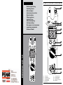
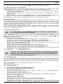
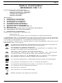
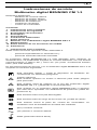
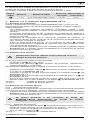
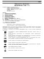
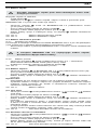
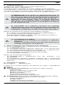
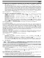
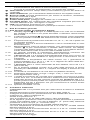
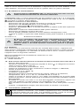
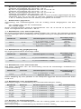
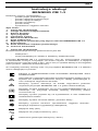
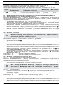
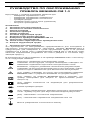
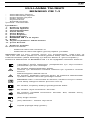
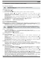
Bild 1: Gerätefrontseite
Fig. 1: Front tester panel
Fig. 1: Panneau avant de l'appareil
Fig. 1: Parte frontal del equipo
Obr. 1: Přední strana přístroje
εικόνα 1: Μπροστινή όψη
ill. 1: Lato anteriore apparecchio
Fig. 1: Voorzijde van het apparaat
Rys. 1 Panel przedni przyrządu
Рис. 1. Фронтальная сторона прибора
Resim 1: Cihaz önyüzü
7
J

08/ 2006
BENNING CM 1-3
08/ 2006
BENNING CM 1-3
D F E I D F E I
08/ 2006
BENNING CM 1-3
D F E I
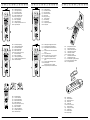
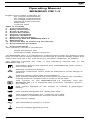
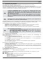
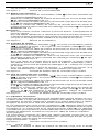
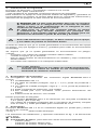
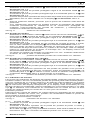
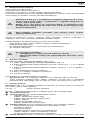
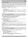
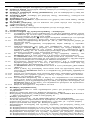
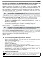
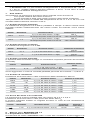
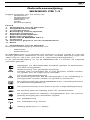
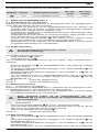
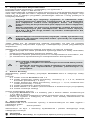
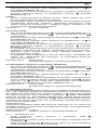
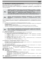
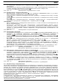
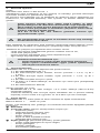
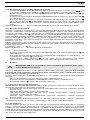
Bild 2: Gleichspannungsmessung
Fig. 2: Direct voltage measurement
Fig. 2: Mesure de tension continue
Fig. 2: Medición de tensión contínua
Obr. 2: Měření stejnosměrného napětí
εικόνα 2: Μέτρηση συνεχούς ρεύματος
ill. 2: Misura tensione continua
Fig. 2: Meten van gelijkspanning
Rys.2: Pomiar napięcia stałego
Рис. 2. Измерение напряжения постоянного тока
Resim 2: Doğru Gerilim Ölçümü
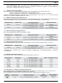
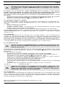
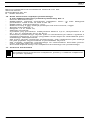
Bild 8: Batteriewechsel
Fig. 8: Battery replacement
Fig. 8: Remplacement de la pile
Fig. 8: Cambio de pila
Obr. 8: Výměna baterie
εικόνα 8: Αντικατάσταση μπαταρίας
ill. 8: Sostituzione batterie
Fig. 8: Vervanging van de batterij
Rys.8: Wymiana baterii
Рис. 8. Замена батарейки
Resim 8: Batarya Değişimi
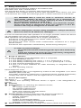
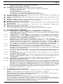
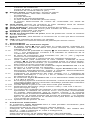
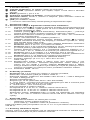
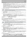
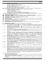
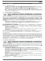
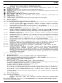
Bild 3: Wechselspannungsmessung
Fig. 3: Alternating voltage measurement
Fig. 3: Mesure de tension alternative
Fig. 3: Medición de tensión alterna
Obr. 3: Měření střídavého napětí
εικόνα 3: Μέτρηση αναλλασσόμενου ρεύματος
ill. 3: Misura tensione alternata
Fig. 3: Meten van wisselspanning
Rys.3: Pomiar napięcia przemiennego
Рис. 3. Измерение напряжения переменного тока
Resim 3: Alternatif Gerilim Ölçümü
CAT.IV
600V
CAT.III
1000V
CM1-3
CAT.IV
600V
V
VoltSensor HOLD
200A
CAT.III
1000V
/
OFF
V
A
750V~/1000V
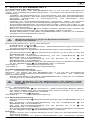
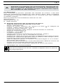
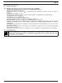
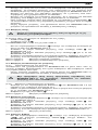
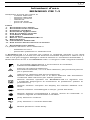
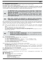
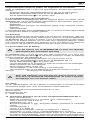
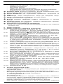
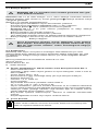
Bild 6: Diodenprüfung/ Durchgangsprüfer mit Summer
Fig. 6: Diode Testing/ Continuity Testing with buzzer
Fig. 6: Contrôle de diodes/ Contrôle de continuité avec
roneur
Fig. 6: Vericación de diodos/ Control de continuidad con
vibrador
obr. 6: Test diod/ Zkoušku obvodu
εικόνα 6: Έλεγχος διόδου/ Έλεγχος συνέχειας με βομβητή
ill. 6: Prova diodi/ Prova di continuità con cicalino
Fig. 6: Diodecontrole/ Doorgangstest met akoestisch
signaal
Rys. 6: Pomiar diody/ Sprawdzenie ciągłości obwodu
См. рис. 6:
Проверка диодов/
Проверка целостности цепи с зуммером
Resim 6: Diyot Ölçümü/ Sesli Uyarıcı ile Süreklilik Kontrolü
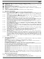
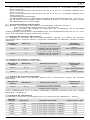
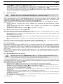
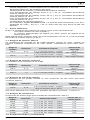
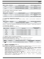
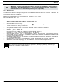
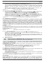
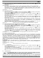
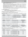
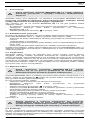
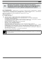
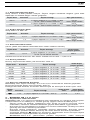
Bild 4: Wechselstrommessung
Fig. 4: AC current measurement
Fig. 4: Mesure de courant alternatif
Fig. 4: Medición de corriente alterna
Obr. 4: Měření střídavého proudu
εικόνα 4: Μέτρηση εναλλασσόμενου ρεύματος
ill. 4: Misura corrente alternata
Fig. 4: Meten van wisselstroom
Rys. 4: Pomiar prądu przemiennego
Рис. 4. Измерение переменного тока
Resim 4: Alternatif Akım Ölçümü
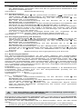
Bild 7: Spannungsindikator mit Summer
g. 7: Voltage indicator with buzzer
g. 7: Indicateur de tension avec roneur
g 7: indicador de tensión con vibrador
obr. 7: Indikátor napětí s bzučákem
εικόνα 7: Ένδειξη τάσης με βομβητή
ill. 7: Indicatore di tensione con cicalino
g. 7: spanningsindicator met zoemer
Rys. 7: Wskaźnik napięcia z sygnalizacja dźwiękową
См. рис. 7:
Индикатор напряжения с зуммером
Resim 7: Akustik gerilim indikatörü
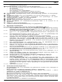
Bild 5: Widerstandsmessung
Fig. 5: Resistance measurement
Fig. 5: Mesure de résistance
Fig. 5: Medición de resistencia
Obr. 5: Měření odporu
εικόνα 5: Μέτρηση αντίστασης
ill. 5: Misura di resistenza
Fig. 5: Weerstandsmeting
Rys.5: Pomiar rezystancji
Рис. 5. Измерение сопротивления
Resim 5: Direnç Ölçümü

08/ 2006
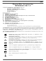
BENNING CM 1-3
1
D
Bedienungsanleitung
BENNING CM 1-3
Stromzangen-Multimeter zur
- Wechselstrommessung
- Wechselspannungsmessung
- Gleichspannungsmessung
- Widerstandsmessung
- Diodenprüfung
- Durchgangsprüfung
Inhaltsverzeichnis
1. Benutzerhinweise
2. Sicherheitshinweise
3. Lieferumfang
4. Gerätebeschreibung
5. Allgemeine Angaben
6. Umgebungsbedingungen
7. Elektrische Angaben
8. Messen mit dem BENNING CM 1-3
9. Instandhaltung
10. Technische Daten des Messzubehörs
11. Umweltschutz
1. Benutzerhinweise
Diese Bedienungsanleitung richtet sich an
- Elektrofachkräfte und
- elektrotechnisch unterwiesene Personen
Das BENNING CM 1-3 ist zur Messung in trockener Umgebung vorge-
sehen und darf nicht in Stromkreisen mit einer höheren Nennspannung als
1000 V DC und 750 V AC eingesetzt werden (Näheres hierzu in Abschnitt 6.
“Umgebungsbedinungen”).
In der Bedienungsanleitung und auf dem BENNING CM 1-3 werden folgende
Symbole verwendet:
Anlegen um GEFÄHRLICH AKTIVE Leiter oder Abnehmen von
diesen ist zugelassen.
Warnung vor elektrischer Gefahr! Steht vor Hinweisen, die
beachtet werden müssen, um Gefahren für Menschen zu
vermeiden.
Dieses Symbol weist auf Gefährdungen beim Gebrauch des
BENNING CM 1-3 hin. (Dokumentation beachten!)
Dieses Symbol auf dem BENNING CM 1-3 bedeutet, dass das
Gerät schutzisoliert (Schutzklasse II) ausgeführt ist.
Dieses Symbol erscheint in der Anzeige für eine entladene
Batterie.
Dieses Symbol kennzeichnet den Bereich „Diodenprüfung“.
Dieses Symbol kennzeichnet den Bereich “Durchgangsprüfung”.
Der Summer dient der akustischen Ergebnisausgabe.
(DC) Gleichspannung.
(AC) Wechsel- Spannung oder Strom.
Masse (Spannung gegen Erde).

08/ 2006
BENNING CM 1-3
2
D
2. Sicherheitshinweise
Das Gerät ist gemäß
DIN VDE 0411 Teil 1/ EN 61010-1
gebaut und geprüft und hat das Werk in einem sicherheitstechnisch einwand-
freien Zustand verlassen.
Um diesen Zustand zu erhalten und einen gefahrlosen Betrieb sicherzustellen,
muss der Anwender die Hinweise und Warnvermerke beachten, die in dieser
Anleitung enthalten sind.
Das BENNING CM 1-3 darf nur in Stromkreisen der Überspan-
nungskategorie III mit max. 1000 V Leiter gegen Erde oder Über-
spannungskategorie IV mit max. 600 V Leiter gegen Erde benutzt
werden.
Beachten Sie, dass Arbeiten an spannungsführenden Teilen und
Anlagen grundsätzlich gefährlich sind. Bereits Spannungen ab
30 V AC und 60 V DC können für den Menschen lebensgefährlich
sein.
Vor jeder Inbetriebnahme überprüfen Sie das Gerät und die
Leitungen auf Beschädigungen.
Ist anzunehmen, dass ein gefahrloser Betrieb nicht mehr möglich ist, ist das
Gerät außer Betrieb zu setzen und gegen unbeabsichtigten Betrieb zu sichern.
Es ist anzunehmen, dass ein gefahrloser Betrieb nicht mehr möglich ist,
- wenn das Gerät oder die Messleitungen sichtbare Beschädigungen
aufweisen,
- wenn das Gerät nicht mehr arbeitet,
- nach längerer Lagerung unter ungünstigen Verhältnissen,
- nach schweren Transportbeanspruchungen.
Um eine Gefährdung auszuschließen
- berühren Sie die Messleitungen nicht an den blanken
Messspitzen,
- stecken Sie die Messleitungen in die entsprechend
gekennzeichneten Messbuchsen am Multimeter
3. Lieferumfang
Zum Lieferumfang des BENNING CM 1-3 gehören:
3.1 ein Stück BENNING CM 1-3
3.2 ein Stück Sicherheitsmessleitung, rot (L = 1,4 m, Spitze Ø 4 mm),
3.3 ein Stück Sicherheitsmessleitung, schwarz (L = 1,4 m, Spitze Ø 4 mm),
3.4 ein Stück Kompakt-Schutztasche,
3.5 zwei Stück 1,5 V-Microbatterie (zur Erstbestückung im Gerät
eingebaut),
3.6 eine Bedienungsanleitung.
Hinweis auf Verschleißteile:
- Das BENNING CM 1-3 wird durch zwei eingebaute 1,5-V-Micro-Batterien
(IEC 6 LR 03) gespeist.
- Die oben genannten Sicherheitsmessleitungen ATL-2 (geprüftes
Zubehör) entsprechen CAT III 1000 V und sind für einen Strom von 10 A
zugelassen.
4. Gerätebeschreibung
Das BENNING CM 1-3 ist ein Digital-Multimeter mit feststehender Gabel und
Stromaufnahmesensor.
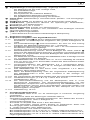
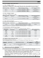
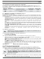
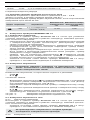
siehe Bild 1: Gerätefrontseite
Die in Bild 1 angegebenen Anzeige- und Bedienelemente werden wie folgt
bezeichnet:
Gehäuse
Drehschalter, dient zur Wahl der gewünschten Funktionen.
- Aus (OFF)
- Wechselspannungsmessung (AC)
- Gleichspannungsmessung (DC)
- Widerstandsmessung
- Dioden- und Durchgangsprüfung
- Wechselstrommessung (AC)

08/ 2006
BENNING CM 1-3
3
D
Digitalanzeige (Flüssigkristallprinzip), angezeigt werden
- der Messwert mit der max. Anzeige 1999,
- die Polaritätsanzeige,
- der Dezimalpunkt,
- das Symbol für die entladene Batterie,
- der festgehaltene Messwert (Holdfunktion),
- die gewählte Durchgangsprüfung mit Summer,
HOLD-Taste (Haltefunktion)/ Umschalt-Taste (Dioden- und Durchgangs-
prüfung)
5 VoltSensor-Taste, zur Ermittlung von AC-Spannungen gegen Erde
6 COM-Buchse, gemeinsame Buchse für Spannungs-, Widerstands,-
Durchgangs- und Diodenprüfung
7 Buchse (positiv1), für V und Ω
8 Stromzangenwulst, schützt vor Leiterberührung.
9 Offene Gabel, zum Einführen und „Umfassen” des einadrigen wechsel-
stromdurchflossenen Leiters.
J LED, für Spannungsindikator
1)
Hierauf bezieht sich die automatische Polaritätsanzeige für Gleichspannung
5. Allgemeine Angaben
5.1 Allgemeine Angaben zum Digital-Multimeter
5.1.1 Die Digitalanzeige 3 ist als 3½-stellige Flüssigkristallanzeige mit 15 mm
Schrifthöhe mit Dezimalpunkt ausgeführt. Der größte Anzeigewert ist
1999.
5.1.2 Die Polaritätsanzeige wirkt automatisch. Es wird nur eine Polung
entgegen der Messleitungsdefinition mit “-” angezeigt.
5.1.3 Die Bereichsüberschreitung wird mit "0L" oder "- 0L" und teilweise einer
akustischen Warnung angezeigt.
Achtung, keine Anzeige und Warnung bei Überlast!
5.1.4 Messwertspeicherung „HOLD“: Durch Betätigen der Taste „HOLD“
lässt sich das Messergebnis speichern. Im Display wird gleichzeitig das
Symbol „H“ eingeblendet. Erneutes Betätigen der Taste schaltet in den
Messmodus zurück.
5.1.5 Die Messrate der Ziffernanzeige des BENNING CM 1-3 beträgt nominal
ca. 1,5 Messungen pro Sekunde.
5.1.6 Das BENNING CM 1-3 schaltet nach ca. 10 min. selbstätig ab. Es lässt
sich nur durch ein Aus-/ Einschalten mittels des Drehschalters wieder
in Funktion bringen.
5.1.7 Temperaturkoeffizient des Messwertes: 0,2 × (angegebene Mess-
genauigkeit)/ °C < 18 °C oder > 28 °C, bezogen auf den Wert bei der
Referenztemperatur von 23 °C.
5.1.8 Das BENNING CM 1-3 wird durch zwei eingebaute 1,5 V Micro-
Batterien (IEC6 LR03) gespeist.
5.1.9 Wenn die Batteriespannung unter die vorgesehene Arbeitsspannung
des BENNING CM 1-3 sinkt, dann erscheint in der Anzeige ein
Batteriesymbol.
5.1.10 Die Lebensdauer der Batterie beträgt etwa 250 Stunden(Alkalibatterie).
5.1.11 Geräteabmessungen: (L x B x H) = 190 x 60 x 40 mm
Gerätegewicht: 265 g
5.1.12
Die Sicherheitsmessleitung und die Messspitzen sind in 4 mm
Stecktechnik ausgeführt. Die Sicherheitsmessleitungen mit den
Messspitzen entsprechen der Nennspannung des BENNING CM 1-3.
Die Messspitzen können durch Schutzkappen geschützt werden und
lassen sich an der Geräteunterseite für den Transport wie auch für
Messaufgaben einclipsen.
5.1.13 Gabelöffnung: 16 mm
6. Umgebungsbedingungen
- Das BENNING CM 1-3 ist nur für Messungen in trockener Umgebung
vorgesehen,
- Barometrische Höhe bei Messungen: Maximal 2000 m,
- Überspannungskategorie/ Aufstellungskategorie: IEC 60664/ IEC 61010-1
→ 600 V Kategorie IV; 1000 V Kategorie III,
- Verschmutzungsgrad: 2,
- Schutzart: IP 30 (DIN VDE 0470-1 IEC/ EN 60529)
3 - erste Kennziffer: Schutz gegen Zugang zu gefährlichen Teilen und
Schutz gegen feste Fremdkörper, > 2,5 mm Durchmesser
0 - zweite Kennziffer: Kein Wasserschutz,
- Arbeitstemperatur und relative Luftfeuchte:
Bei Arbeitstemperatur von 0 °C bis 30 °C: relative Luftfeuchte kleiner 80 %,
Bei Arbeitstemperatur von 30 °C bis 40 °C: relative Luftfeuchte kleiner 75 %,
Bei Arbeitstemperatur von 40 °C bis 50 °C: relative Luftfeuchte kleiner 45 %,
- Lagerungstemperatur:

08/ 2006
BENNING CM 1-3
4
D
Das BENNING CM 1-3 kann bei Temperaturen von - 20 °C bis + 60 °C,
relative Luftfeuchte kleiner 80 %, gelagert werden. Dabei ist die Batterie
aus dem Gerät heraus zu nehmen.
7. Elektrische Angaben
Bemerkung: Die Messgenauigkeit wird angegeben als Summe aus
- einem relativen Anteil des Messwertes und
- einer Anzahl von Digit (d.h., Zahlenschritte der letzten Stelle).
Diese Messgenauigkeit gilt bei der Temperatur von 23 °C ± 5 °C und einer
relativen Luftfeuchtigkeit kleiner 80 %.
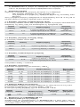
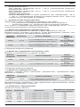
7.1 Wechselspannungsbereich
Der Eingangswiderstand beträgt 2 MΩ parallel 100 pF. Der Messwert wird durch
Mittelwertgleichrichtung gewonnen und als Effektivwert angezeigt.
Messbereich Auflösung Messgenauigkeit Überlastschutz
200 V 0,1 V ± (1,5 % des Messwertes + 5 Digit)
im Frequenzbereich 50 Hz - 500 Hz
750 Veff
1000 V Gleichspannung
750 V 1 V ± (1,5 % des Messwertes + 5 Digit)
im Frequenzbereich 50 Hz - 500 Hz
750 Veff
1000 V Gleichspannung
7.2 Gleichspannungsbereich
Der Eingangswiderstand beträgt 2 MΩ.
Messbereich Auflösung Messgenauigkeit Überlastschutz
200 V 0,1 V ± (1,0 % des Messwertes + 2 Digit) 750 Veff
1000 V Gleichspannung
1000 V 1 V ± (1,0 % des Messwertes + 2 Digit) 750 Veff
1000 V Gleichspannung
7.3 Wechselstrombereich
(Stromgabelöffnung umfasst einadrigen wechselstromführenden Leiter).
Messbereich Auflösung Messgenauigkeit Überlastschutz
200 A 0,1 A ± (3,0 % des Messwertes + 3 Digit)
im Frequenzbereich 50 - 60 Hz 400 A
zusätzlicher Fehler bei einer parallel liegenden stromführenden Leitung:
< 0,08 A/A
7.4 Widerstandsbereiche
Überlastschutz bei Widerstandsmessungen 600 Veff
Messbereich Auflösung Messgenauigkeit Max. Leerlaufspannung
200 Ω 0,1 Ω
±
(1,0 % des Messwertes + 5 Digit) 1,3 V
2 kΩ 1 Ω
±
(1,0 % des Messwertes + 2 Digit) 1,3 V
20 kΩ 10 Ω
±
(1,0 % des Messwertes + 2 Digit) 1,3 V
200 kΩ 100 Ω
±
(1,0 % des Messwertes + 2 Digit) 1,3 V
2 MΩ 1 kΩ
±
(1,0 % des Messwertes + 2 Digit) 1,3 V
20 MΩ 10 kΩ
±
(1,9 % des Messwertes + 5 Digit) 1,3 V
7.5 Dioden- und Durchgangsprüfung
Die angegebene Messgenauigkeit gilt im Bereich zwischen 0,4 V und 0,8 V.
Überlastschutz bei Diodenprüfungen: 600 Veff
Der eingebaute Summer ertönt bei einem Widerstand kleiner 50 Ω.
Mess-
bereich Auflösung Messgenauigkeit Max.
Messstrom
Max. Leerlauf-
spannung
1 mV
± (1,5 % des Messwertes + 0,05 V)
1,5 mA 3,0 V

08/ 2006
BENNING CM 1-3
5
D
8. Messen mit dem BENNING CM 1-3
8.1 Vorbereiten der Messungen
Benutzen und lagern Sie das BENNING CM 1-3 nur bei den angegebenen
Lager- und Arbeitstemperaturbedingungen, vermeiden Sie dauernde Sonnen-
einstrahlung.
- Angaben von Nennspannung und Nennstrom auf den Sicherheitsmess-
leitungen überprüfen. Die zum Lieferumfang gehörenden Sicherheitsmess-
leitungen entsprechen in Nennspannung und Nennstrom dem
BENNING CM 1-3.
- Isolation der Sicherheitsmessleitungen überprüfen. Wenn die Isolation
beschädigt ist, sind die Sicherheitsmessleitungen sofort auszusondern.
- Sicherheitsmessleitungen auf Durchgang prüfen. Wenn der Leiter in der
Sicherheitsmessleitung unterbrochen ist, sind die Sicherheitsmessleitungen
sofort auszusondern.
- Bevor am Drehschalter 2 eine andere Funktion gewählt wird, müssen die
Sicherheitsmessleitungen von der Messstelle getrennt werden.
- Starke Störquellen in der Nähe des BENNING CM 1-3 können zu instabiler
Anzeige und zu Messfehlern führen.
8.2 Spannungsmessung
Maximale Spannung gegen Erdpotential beachten!
Elektrische Gefahr!
Die höchste Spannung, die an den Buchsen,
- COM-Buchse, schwarz 6
- Buchse für V, Ω 7 für Spannungs-, Widerstandsmessungen und Dioden-
und Durchgangsprüfungen,
des BENNING CM 1-3 gegenüber Erdpotential liegen darf, beträgt 1000 V.
- Mit dem Drehschalter 2 die gewünschte Funktion (V AC) oder (V DC) am
BENNING CM 1-3 wählen.
- Die schwarze Sicherheitsmessleitung mit der COM-Buchse 6 am
BENNING CM 1-3 kontaktieren.
- Die rote Sicherheitsmessleitung mit der Buchse für V, Ω 7 am
BENNING CM 1-3 kontaktieren.
- Die Sicherheitsmessleitungen mit den Messpunkten kontaktieren, Messwert
an der Digitalanzeige 3 am BENNING CM 1-3 ablesen.
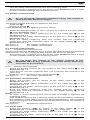
siehe Bild 2: Gleichspannungsmessung
siehe Bild 3: Wechselspannungsmessung
8.3 Wechselstrommessung
8.3.1 Vorbereiten der Messungen
Benutzen und lagern Sie das BENNING CM 1-3 nur bei den angegebenen
Lager- und Arbeitstemperaturbedingungen, vermeiden Sie dauernde
Sonneneinstrahlung.
- Starke Störquellen in der Nähe des BENNING CM 1-3 können zu instabiler
Anzeige und zu Messfehlern führen.
Keine Spannung an die Messbuchsen des Gerätes legen!
Entfernen Sie eventuell die angeschlossenen Sicherheitsmess-
leitungen.
8.3.2 Strommessung
- Mit dem Drehschalter den mit dem A gekennzeichneten Bereich wählen.
- Die offene Gabel über den stromführenden Leiter schieben, so, dass sich
der Leiter im Öffnungsbereich befindet.
- Die Digitalanzeige ablesen.
siehe Bild 4: Wechselstrommessung
8.4 Widerstandsmessung
- Mit dem Drehschalter die gewünschte Funktion (Ω) am BENNING CM 1-3
wählen.
- Die schwarze Sicherheitsmessleitung mit der COM-Buchse 6 am
BENNING CM 1-3 kontaktieren.
- Die rote Sicherheitsmessleitung mit der Buchse für V, Ω 7 am
BENNING CM 1-3 kontaktieren.
- Die Sicherheitsmessleitungen mit den Messpunkten kontaktieren, Messwert
an der Digitalanzeige 3 am BENNING CM 1-3 ablesen.
Hinweis:
- Stellen Sie für eine richtige Messung sicher, dass an der Messstelle keine
Spannung anliegt.
- Das Messergebnis bei kleinen Widerständen kann verbessert werden,

08/ 2006
BENNING CM 1-3
6
D
indem der Widerstand der Sicherheitsmessleitung zuvor mit Kurzschluss
der Messspitzen gemessen wird und der so gewonnene Widerstand vom
Ergebnis subtrahiert wird.
siehe Bild 5: Widerstandsmessung
8.5 Diodenprüfung
- Mit dem Drehschalter 2 die gewünschte Funktion ( ) und durch die
Taste HOLD- / „Diodenprüfung“ am BENNING CM 1-3 wählen.
- Die schwarze Sicherheitsmessleitung mit der COM-Buchse 6 am
BENNING CM 1-3 kontaktieren.
- Die rote Sicherheitsmessleitung mit der Buchse für V, Ω 7 am
BENNING CM 1-3 kontaktieren.
- Die Sicherheitsmessleitungen mit den Diodenanschlüssen kontaktieren, den
Messwert an der Digitalanzeige 3 am BENNING CM 1-3 ablesen.
- Für eine normale in Flussrichtung angelegte Si-Diode wird die Flussspan-
nung zwischen 0,400 V bis 0,900 V angezeigt. Die Anzeige „000“ deutet
auf einen Kurzschluss in der Diode hin, die Anzeige „OL“ deutet auf eine
Unterbrechung in der Diode hin.
- Für eine in Sperrrichtung angelegte Diode wird „OL“ angezeigt. Ist die
Diode fehlerhaft, werden „000“ oder andere Werte angezeigt.
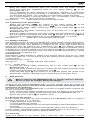
siehe Bild 6: Diodenprüfung/ Durchgangsprüfung mit Summer
8.6 Durchgangsprüfung mit Summer
- Mit dem Drehschalter 2 die gewünschte Funktion ( ) und durch die
Taste HOLD- / „Durchgangsprüfung“ am BENNING CM 1-3 wählen.
- Die schwarze Sicherheitsmessleitung mit der COM-Buchse 6 am
BENNING CM 1-3 kontaktieren.
- Die rote Sicherheitsmessleitung mit der Buchse für V, Ω 7 am
BENNING CM 1-3 kontaktieren.
- Die Sicherheitsmessleitungen mit den Messpunkten kontaktieren. Unter-
schreitet der Leitungswiderstand zwischen der COM-Buchse 6 und der
Buchse für V, Ω 7 50 Ω, ertönt im BENNING CM 1-3 der eingebaute
Summer.
siehe Bild 6: Diodenprüfung/ Durchgangsprüfung mit Summer
8.7 Spannungsindikator
Die Spannungsindikatorfunktion ist aus jeder Stellung des Drehschalters
möglich. Als Spannungsindikator werden keine Messleitungen benötigt (berüh-
rungslose Erfassung eines Wechselfeldes). Im Kopfbereich hinter der LED
befindet sich der Aufnahmesensor. Bei Betätigung der "VoltSensor"-Taste 5
erlischt das Anzeigedisplay (falls eingeschaltet). Wird eine Phasen-Spannung
lokalisiert, ertönt ein akustisches und rotes LED Signal J. Eine Anzeige erfolgt
nur in geerdeten Wechselstromnetzen! Mit einer einpoligen Messleitung kann
auch die Phase ermittelt werden.
Praxistipp:
Unterbrechungen (Kabelbrüche) in offenliegenden Kabeln, z. B. Kabeltrommel,
Lichterkette usw., lassen sich von der Einspeisestelle (Phase) bis zur
Unterbrechungsstelle verfolgen.
Funktionsbereich: ≥ 230 V
siehe Bild 7: Spannungsindikator
8.7.1 Phasenprüfung
- Die schwarze Sicherheitsmessleitung mit der Buchse COM 6 am
BENNING CM 1-3 kontaktieren.
- Die Sicherheitsmessleitung mit dem Messpunkt (Anlagenteil) kontaktieren
und die Taste „VoltSensor“ 5 betätigen.
- Wenn die rote LED J leuchtet und ein akustisches Signal ertönt,
liegt an diesem Messpunkt (Anlagenteil) die Phase einer geerdeten
Wechselspannung vor.
9. Instandhaltung
Vor dem Öffnen das BENNING CM 1-3 unbedingt spannungs-
frei machen! Elektrische Gefahr!
Die Arbeit an dem geöffneten BENNING CM 1-3 unter Spannung ist ausschließ-
lich Elektrofachkräften vorbehalten, die dabei besondere Maßnahmen zur
Unfallverhütung treffen müssen.
So machen Sie das BENNING CM 1-3 spannungsfrei, bevor Sie das Gerät
öffnen:
- Entfernen Sie zuerst beide Sicherheitsmessleitungen vom Messobjekt.
- Entfernen Sie dann beide Sicherheitsmessleitungen vom BENNING CM 1-3.

08/ 2006
BENNING CM 1-3
7
D
- Schalten Sie den Drehschalter 2 in die Schaltstellung „OFF“.
9.1 Sicherstellen des Gerätes
Unter bestimmten Voraussetzungen kann die Sicherheit im Umgang mit dem
BENNING CM 1-3 nicht mehr gewährleistet sein; zum Beispiel bei:
- Sichtbaren Schäden am Gerät, und/ oder an den Sicherheitsmessleitungen,
- Fehlern bei Messungen,
- Erkennbaren Folgen von längerer Lagerung unter unzulässigen Bedin-
gungen und
- Erkennbaren Folgen von außerordentlicher Transportbeanspruchung.
In diesen Fällen ist das BENNING CM 1-3 sofort abzuschalten, von der
Messstelle zu entfernen und gegen erneute Nutzung zu sichern.
9.2 Reinigung
Reinigen Sie das Gehäuse äußerlich mit einem sauberen und trockenen Tuch
(Ausnahme spezielle Reinigungstücher). Verwenden Sie keine Lösungs- und/
oder Scheuermittel, um den Spannungsprüfer zu reinigen. Achten Sie unbedingt
darauf, dass das Batteriefach und die Batteriekontakte nicht durch auslaufendes
Batterie-Elektrolyt verunreinigt werden.
Falls Elektrolytverunreinigungen oder weiße Ablagerungen im Bereich der
Batterie oder des Batteriegehäuses vorhanden sind, reinigen Sie auch diese
mit einen trockenem Tuch.
9.3 Batteriewechsel
Vor dem Öffnen das BENNING CM 1-3 unbedingt spannungs-
frei machen! Elektrische Gefahr!
Das BENNING CM 1-3 wird von zwei 1,5-V-Micro-Batterien gespeist. Ein
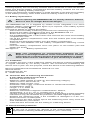
Batteriewechsel (siehe Bild 8) ist dann erforderlich, wenn in der Anzeige das
Batteriesymbol erscheint.
So wechseln Sie die Batterien:
- Entfernen Sie die Sicherheitsmessleitungen vom Messkreis.
- Entfernen Sie die Sicherheitsmessleitungen vom BENNING CM 1-3.
- Bringen Sie den Drehschalter 2 in die Schaltstellung „OFF“.
- Legen Sie das BENNING CM 1-3 auf die Frontseite, und lösen Sie die
Schraube am Batteriefachdeckel.
- Heben Sie den Batteriefachdeckel vom Unterteil ab.
- Entnehmen Sie die entladene Batterie aus dem Batteriefach.
- Legen Sie die neuen Batterien polrichtig ins Batteriefach.
- Schieben Sie den Batteriedeckel im unteren Bereich in die Aufnahmenut
und ziehen Sie die Schraube an.
siehe Bild 8: Batteriewechsel
Leisten Sie Ihren Beitrag zum Umweltschutz! Batterien dürfen
nicht in den Hausmüll. Sie können bei einer Sammelstelle für
Altbatterien bzw. Sondermüll abgegeben werden. Informieren
Sie sich bitte bei Ihrer Kommune.
9.4 Kalibrierung
Um die angegebenen Genauigkeiten der Messergebnisse zu erhalten, muss das
Gerät regelmäßig durch unseren Werksservice kalibriert werden. Wir empfehlen ein
Kalibrierintervall von einem Jahr. Senden Sie hierzu das Gerät an folgende Adresse:
Benning Elektrotechnik & Elektronik GmbH & Co. KG
Service Center
Robert-Bosch-Str. 20
D - 46397 Bocholt
10. Technische Daten des Messzubehörs
4 mm Sicherheitsmessleitung ATL 2
- Norm: EN 61010-031,
- Maximale Bemessungsspannung gegen Erde ( ) und Messkategorie:
1000 V CAT III, 600 V CAT IV,
- Maximaler Bemessungsstrom: 10 A,
- Schutzklasse II (), durchgängige doppelte oder verstärkte Isolierung,
- Verschmutzungsgrad: 2,
- Länge: 1,4 m, AWG 18,
- Umgebungsbedingungen:
Barometrische Höhe bei Messungen: Maximal 2000 m,
Temperatur: 0°C bis + 50 °C, Feuchte 50 % bis 80 %
- Verwenden Sie die Messleitungen nur im einwandfreien Zustand und
entsprechend dieser Anleitung, da ansonsten der vorgesehene Schutz

08/ 2006
BENNING CM 1-3
8
D
beeinträchtigt sein kann.
- Sondern Sie die Messleitung aus, wenn die Isolierung beschädigt ist oder
eine Unterbrechung in Leitung/ Stecker vorliegt.
- Berühren Sie die Messleitung nicht an den blanken Kontaktspitzen. Fassen
Sie nur den Handbereich an!
- Stecken Sie die abgewinkelten Anschlüsse in das Prüf- oder Messgerät.
11. Umweltschutz
Bitte führen Sie das Gerät am Ende seiner Lebensdauer den zur
Verfügung stehenden Rückgabe- und Sammelsystemen zu.

08/ 2006
BENNING CM 1-3
9
Operating Manual
BENNING CM 1-3
Digital current clamp multimeter for
- AC current measurements
- AC voltage measurements
- DC voltage measurements
- resistance measurements
- diode tests
- continuity tests
Table of contents
1. User instructions
2. Safety instructions
3. Scope of delivery
4. Device description
5. General information
6. Ambient conditions
7. Electrical specifications
8. Measuring with the BENNING CM 1-3
9. Maintenance
10. Technical data of measuring accessories
11. Environmental protection
1. User instructions
This operating manual is intended for
- skilled electricians and
- electrotechnically trained personnel.
The BENNING CM 1-3 is intended for measurements under dry ambient condi-
tions. It must not be used in electrical circuits with a nominal voltage higher then
1000 V DC and 750 V AC (see section 6 „Ambient conditions“ for details).
The following symbols are used in this operating manual and on the
BENNING CM 1-3:
Application around and removal from HAZARDOUS LIVE conduc-
tors is permitted.
Warning of electrical danger!
Indicates instructions which must be followed to avoid danger to
persons.
Attention! Must comply with documentation!
This symbol indicates that the information provided in the operating
manual must be complied with in order to avoid risks.
This symbol on the BENNING CM 1-3 indicates that the
BENNING CM 1-3 is equipped with protective insulation (protec-
tion class II).
This symbol appears on the display to indicate a discharged
battery.
This symbol designates the „diode test“ field.
This symbol designates the „continuity test“ field.
The buzzer is intended for acoustic result output.
(DC) Direct voltage
(AC) Alternating voltage or current
Ground (voltage against ground)

08/ 2006
BENNING CM 1-3
10
2. Safety instructions
The instrument is built and tested in accordance with
DIN VDE 0411 Part 1/ EN 61010-1
and has left the factory in perfectly safe technical condition.
To preserve this condition and to ensure safe operation of the device, the user
must observe the notes and warnings given in these instructions at all times.
The BENNING CM 1-3 must be used in electrical circuits of
overvoltage category III with a conductor for a maximum of
1000 V to earth or of overvoltage category IV with a conductor
for a maximum of 600 V to earth only.
Please observe that work on live parts and electrical compo-
nents of all kinds is dangerous! Even low voltages of 30 V AC
and 60 V DC may be dangerous to human life!
Before starting the current clamp multimeter, always check the
device as well as all cables for damages.
If it can be assumed that safe operation is no longer possible, switch the device
off immediately and secure it against unintended operation.
Safe operation can be assumed to be no longer possible, if
- the device or the measuring lines exhibit visible damages,
- the device no longer works,
- the device has been stored under unfavourable conditions for a longer
period of time,
- the device was exposed to extraordinary stress during transport.
In order to prevent danger
- do not touch the bare measuring probe tips of the measuring
lines,
- insert the measuring lines into the respectively designated
measuring socket of the multimeter.
3. Scope of delivery
The scope of delivery of the BENNING CM 1-3 comprises:
3.1 One BENNING CM 1-3,
3.2 One safety measuring line, red (L = 1.4 m; probe tip Ø = 4 mm),
3.3 One safety measuring line, black (L = 1.4 m; probe tip Ø = 4 mm),
3.4 One compact protective pouch,
3.5 Two 1,5 V micro batteries for initial assembly is integrated into the
device,
3.6 One operating manual.
Parts subject to wear:
- The BENNING CM 1-3 is supplied by means of two integrated 1,5 V micro
batteries (IEC 6 LR 03).
- The safety measuring cables ATL-2 mentioned above (tested accessories)
comply with CAT III 1000 V and are approved for a current of 10 A.
4. Device description
See figure 1: Device front
The display and operating elements shown in figure 1 are designated as
follows:
1 Housing
2 Rotary switch, for selecting the desired function,
- OFF
- AC voltage measurement
- DC voltage measurement
- resistance measurement
- diode and continuity test with buzzer
- AC current measurement
3 Digital display (liquid-crystal type) with following indications:
- measurement reading with max. indication 1999
- polarity indication
- decimal point
- symbol for discharged battery
- measurement reading retained (hold function)
- selected continuity test with buzzer
4 HOLD button (hold function)/ change-over button (diode and continuity test)

08/ 2006
BENNING CM 1-3
11
5 VoltSensor key, for determining AC voltage to earth,
6 COM jack, common jack for voltage/ resistance measurements, continuity
and diode tests,
7 Jack (positive1), for V and Ω
8 Bulge for current clamp, protects against contact with conductor,
9 Open fork for inserting and gripping the single conductor containing AC
current.
J LED, for voltage indicator
1) This is what the automatic polarity indication for DC voltage refers to
5. General information
5.1 General information on the current clamp multimeter
5.1.1 The digital display 3 is a 3½-digit LC display with a font size of 15 mm
and a decimal point. The highest numerical value to be displayed is
1999.
5.1.2 The polarity indication 3 works automatically. Only a polarity contrary
to the jack definition is indicated with „-“.
5.1.3 The range exceedance is indicated by „OL“ or „-OL“ and partly by an
acoustic warning.
Attention, no indication and warning in case of overload!
5.1.4 Measured value storage “HOLD“: Press the “HOLD“ key 4 to store the
measuring result. At the same time, the display shows the “H“ symbol.
Press the key again to switch back to the measuring mode.
5.1.5 The nominal measuring rate of the BENNING CM 1-3 is 1.5 measure-
ments per second.
5.1.6 The BENNING CM 1-3 is switched off automatically after approx.
10 minutes. It can only be switched on again by switching the rotating
switch off and on again.
5.1.7 Temperature coefficient of the measured value: 0.2 x (stated measuring
accuracy)/ °C < 18 °C or > 28 °C, related to the value for the reference
temperature of 23 °C.
5.1.8 The BENNING CM 1-3 is supplied by means of two 1,5 V micro bat-
teries (IEC 6 LR 03).
5.1.9 If the battery voltage falls below the specified operating voltage of the
BENNING CM 1-3, a battery symbol appears on the display.
5.1.10 The battery life is approx. 250 hours (alkaline battery).
5.1.11 Dimensions of the BENNING CM 1-3: (L x W x H) = 190 x 60 x 40 mm
Weight: 265 g
5.1.12 The safety measuring lines are designed in 4 mm plug-in technology.
The enclosed safety measuring lines are explicitly intended for the
nominal voltage and the nominal current of the BENNING CM 1-3. The
measuring tips can be protected by caps and can be clipped onto the
underside of the unit for easier transport and for certain measuring
tasks.
5.1.13 Fork opening: 16 mm
6. Ambient conditions
- The BENNING CM 1-3 is intended for measurements under dry ambient
conditions,
- Maximum barometric height for measurements: 2000 m,
- Overvoltage category / installation category: IEC 60664-1/ IEC 61010-1 →
600 V category IV; 1000 V category III
- Contamination class: 2,
- Protection category: IP 30 (DIN VDE 0470-1 IEC/ EN 60529)
3 - first index: protection against access to dangerous parts and protection
against solid impurities of a diameter > 2.5 mm
0 - second index: no protection against water
- Operating temperature and relative air humidity:
For operating temperatures from 0 °C to 30 °C: relative air humidity lower
than 80 %,
For operating temperatures from 31 °C to 40 °C: relative air humidity lower
than 75 %,
For operating temperatures from 41 °C to 50 °C: relative air humidity lower
than 45 %,
- Storage temperature: The BENNING CM 8 can be stored at temperatures
between - 20 °C and + 60 °C (air humidity 0 to 80 %). During storage, the
battery should be removed.
7. Electrical specifications
Note: The measuring accuracy is specified as the sum of:
- a relative part of the measured value and
- a number of digits (i.e. counting steps of the last digit).
This measuring accuracy applies to temperatures from 23 °C ± 5 °C and a rela-

08/ 2006
BENNING CM 1-3
12
tive air humidity lower than 80 %.
7.1 AC voltage ranges
The input resistance is 2 MΩ in parallel 100 pF. The measurement reading is
obtained by rectification of average reading and displayed as actual value.
Measuring range Resolution Measurement accuracy Overload protection
200 V 0.1 V ± (1.5 %
of reading + 5 digit)
in frequency range 50 Hz - 500 Hz
750 Veff
1000
DC voltage
750 V 1 V ± (1.5 %
of reading + 5 digit)
in frequency range 50 Hz - 500 Hz
750 Veff
1000
DC voltage
7.2 DC voltage ranges
The input resistance is 2 MΩ.
Measuring range Resolution Measurement accuracy Overload protection
200 V 0.1 V ± (1.0 %
of reading + 2 digit)
750 Veff
1000
DC voltage
1000 V 1 V ± (1.0 %
of reading + 2 digit)
750 Veff
1000
DC voltage
7.3 AC current ranges
(Current-fork opening embraces AC wire).
Measuring range Resolution Measurement accuracy Overload protection
200 A 0.1 A
± (3.0 % of the measured value + 3 digits)
within the frequency range 50 Hz – 60 Hz
400 A
Additional error in parallel current-conducting wire: < 0.08 A/ A.
7.4 Resistance measuring ranges
Overload protection for resistance measurements: 600 Veff
Measuring
range Resolution Measuring accuracy Max. open-circuit
voltage
200 Ω 0.1 Ω
±
(1.0 % of the measured value+ 5 digits) 1.3 V
2 kΩ 1 Ω
±
(1.0 % of the measured value + 2 digits) 1.3 V
20 kΩ 10 Ω
±
(1.0 % of the measured value + 2 digits) 1.3 V
200 kΩ 100 Ω
±
(1.0 % of the measured value + 2 digits) 1.3 V
2 MΩ 1 kΩ
±
(1.0 % of the measured value + 2 digits) 1.3 V
20 MΩ 10 kΩ
±
(1.9 % of the measured value + 5 digits) 1.3 V
7.5 Diode and continuity test
The stated measuring accuracy applies to a range between 0.4 V and 0.8 V.
Overload protection: 600 Veff
The integrated buzzer sounds at a resistance R lower than 50 Ω.
Measuring
range Resolution Measuring accuracy Max. measuring
current
Max.
open-circuit
voltage
1 mV
± (1.5 % of the measured value +
0.05 V)
1.5 mA 3.0 V
8. Measuring with the BENNING CM 1-3
8.1 Preparing the measurement
Operate and store the BENNING CM 1-3 at the specified storage and operating
temperatures only! Do not permanently expose the device to sunlight.
- Check stated nominal voltage and nominal current on the safety measuring
lines. Nominal voltage and current of the enclosed safety measuring lines
comply with the respective values of the BENNING CM 1-3.
- Check insulation of the safety measuring lines. If the insulation is damaged,
the safety measuring lines must be replaced immediately.
- Check the safety measuring lines for continuity. If the conductor in the
safety measuring line is interrupted, replace the safety measuring lines
immediately.
- Before selecting another function by means of the rotary switch 2, discon-

08/ 2006
BENNING CM 1-3
13
nect the safety measuring lines from the measuring point.
- Strong sources of interference in the vicinity of the BENNING CM 1-3 might
involve unstable readings and measuring errors.
8.2 Voltage measurements
Do not exceed the maximum permitted voltage with respect to
earth potential! Electrical danger!
The highest voltage that may be applied to the jacks
- COM jack 6
- jack for V and Ω 7
of the BENNING CM 1-3 against ground is 1000 V.
- Select the desired function (V AC) or (V DC) by means of the rotary switch
2 of the BENNING CM 1-3.
- Connect the black safety measuring line to the COM jack 6 of the
BENNING CM 1-3.
- Connect the red safety measuring line to the jack for V and Ω 7 of the
BENNING CM 1-3.
- Bring the safety measuring lines into contact with the measuring
points and read the measured value on the digital display 3 of the
BENNING CM 1-3.
See figure 2: DC voltage measurement
See figure 3: AC voltage measurement
8.3 Current measurements
8.3.1 Preparing the measurement
Operate and store the BENNING CM 1-3 at the specified storage and operating
temperatures only! Do not permanently expose the device to sunlight.
- Strong sources of interference in the vicinity of the BENNING CM 1-3 might
involve unstable readings and measuring errors.
Do not apply any voltage to the output contacts of the
BENNING CM 1-3! Any possibly connected safety measuring
lines have to be removed.
8.3.2 Current measurements
- Select the desired function (A~) by means of the rotary switch 2 of the
BENNING CM 1-3.
- Push the fork over the conductor wire. The conductor wire must be in the
open area.
- Read the value indicated on the digital display 3.
See figure 4: AC current measurement
8.4 Resistance measurements
- Select the function (Ω) by means of the rotary switch 2 of the
BENNING CM 1-3.
- Connect the black safety measuring line to the COM jack 6 of the
BENNING CM 1-3.
- Connect the red safety measuring line to the jack for V and Ω 7 of the
BENNING CM 1-3.
- Bring the safety measuring lines into contact with the measuring
points and read the measured value on the digital display 3 of the
BENNING CM 1-3.
Note:
- To obtain a correct measurement, ensure that no voltage is applied to the
measuring point.
- With small resistances, the measuring result can be improved by measuring
the resistance of the safety measuring wires beforehand by short-circuiting
the measuring tips and subtracting the reading obtained from the resistance
measured.
See figure 5: Resistance measurement
8.5 Diode tests
- Select the function ( ) by means of the rotary switch 2 of the
BENNING CM 1-3 and press the HOLD -key „diode test“.
- Connect the black safety measuring line to the COM jack 6 of the
BENNING CM 1-3.
- Connect the red safety measuring line to the jack for V, Ω 7 of the
BENNING CM 1-3.

08/ 2006
BENNING CM 1-3
14
- Bring the safety measuring lines into contact with the diode connec-
tions and read the measured value on the digital display 3 of the
BENNING CM 1-3.
- For a standard Si diode applied in conduction direction, a conduction
voltage between 0.400 V and 0.900 V is displayed. „000“ indicates a short-
circuit inside the diode, „OL“ indicates an interruption inside the diode.
- For a diode applied in reverse direction, „OL“ is indicated. If the diode is
defective, „000“ or other values are indicated.
See figure 6: Diode test/ continuity test with buzzer
8.6 Continuity tests with buzzer
- Select the function ( ) by means of the rotary switch 2 of the
BENNING CM 1-3 and press the HOLD -key „continuity test“.
- Connect the black safety measuring line to the COM jack 6 of the
BENNING CM 1-3.
- Connect the red safety measuring line to the jack for V, Ω 7 of the
BENNING CM 1-3.
- Bring the safety measuring lines into contact with the measuring points. If
the line resistance between the COM jack 6 and the jack for V, Ω 7 falls
below 50 Ω, the integrated buzzer of the BENNING CM 1-3 sounds.
See figure 6: Diode test/ continuity test with buzzer
8.7 Voltage indicator
The voltage indicator function is possible from each position of the rotary switch.
No measuring lines are required as voltage indicator (non-contact detection of
an alternating field). The detector is located on the upper part of the device
behind the LED. By pressing the „VoltSensor“ key 5, the display indication
disappears (if the display is switched on). If a phase voltage is localized, this is
indicated by an acoustic signal and a red LED signal J. An indication is made
in earthed AC current networks only! The phase can be determined by means
of a single-pole measuring line.
Practical hint:
Interruptions (cable breaks) in cables lying around openly such as e.g. cable
reels, fairy lights etc. can be traced from the feeding point (phase) to the point
of interruption.
Functional range: ≥ 230 V
See figure 7: Voltage indicator with buzzer
8.7.1 Phase test
- Connect the black safety measuring line to the COM jack 6 of the
BENNING CM 1-3.
- Bring the safety measuring line into contact with the measuring point of the
system part and press the „VoltSensor“ key 5.
- If the red LED lights J and if there is an acoustic signal, the phase of an
earthed AC voltage is applied to this measuring point (system part).
9. Maintenance
Before opening the BENNING CM 1-3, strictly observe that the
device is free of voltage! Electrical danger!
Working on the opened BENNING CM 1-3 under voltage must be carried out
by skilled electricians only who must observe special precautions for the
prevention of accidents!
To make sure that the BENNING CM 1-3 is free of voltage before opening the
device, proceed as follows:
- First, remove both safety measuring lines from the object to be measured.
- Then, remove both safety measuring lines from the BENNING CM 1-3.
- Switch the rotary switch 2 to position „OFF“.
9.1 Securing the device
Under certain circumstances, safe operation of the BENNING CM 1-3 might no
longer be ensured, e.g. in case of:
- visible damages of the housing,
- incorrect measuring results,
- recognizable consequences of prolonged storage under inadmissible condi-
tions and
- recognizable consequences of extraordinary stress due to transport.
In such cases, immediately switch off the BENNING CM 1-3, disconnect it from
the measuring points and secure it against further use.
9.2 Cleaning
Clean the exterior of the device with a clean dry cloth (exception: special

08/ 2006
BENNING CM 1-3
15
cleaning wipers). Do not use any solvents and/or abrasives to clean the device.
Make sure that the battery compartment and the battery contacts are not con-
taminated by leaking battery electrolyte.
If there are electrolyte contamination or white deposits in the area of the battery
or the battery housing, clean these areas as well by means of a dry cloth.
9.3 Battery replacement
Before opening the BENNING CM 1-3, strictly observe that the
device is free of voltage! Electrical danger!
The BENNING CM 1-3 is supplied by means of two integrated 1.5 V micro
batteries. Battery replacement (see figure 8) is required, if the battery symbol
appears on the display 3.
Proceed as follows to replace the battery:
- Disconnect the safety measuring lines from the measuring circuit.
- Remove the safety measuring lines from the BENNING CM 1-3.
- Switch the rotary switch 2 to position „OFF“.
- Put the BENNING CM 1-3 face down and unscrew the screw of the battery
compartment cover.
- Lift off the battery compartment cover from the bottom part of the battery
compartment.
- Remove the discharged battery from the battery compartment.
- Insert the new batteries into the battery compartment observing correct
polarity.
- Lock the battery compartment cover into place on the bottom part and
tighten the screw.
See figure 8: Battery replacement
Make your contribution for environmental protection! Do not
dispose of discharged batteries via the household waste. Instead,
return them to a collecting point for discharged batteries or spezial
waste. Please look for information in your community‘s facilities.
9.4 Calibration
To maintain accuracy of the measuring results, the device must be recalibrated
in regular intervals by our factory service. We recommend recalibrating the
device once a year. For this purpose, send the device to the following address:
Benning Elektrotechnik & Elektronik GmbH & Co. KG
Service Center
Robert-Bosch-Str. 20
D - 46397 Bocholt
10. Technical data of measuring accessories
4 mm safety measuring line ATL 2
- Standard: EN 61010-031,
- Maximum rated voltage to earth ( ) and measuring category:
1000 V CAT III, 600 V CAT IV,
- Maximum rated current: 10 A,
- Protection class II (), continuous double or reinforced insulation,
- Contamination class: 2,
- Length: 1.4 m, AWG 18,
- Ambient conditions:
Maximum barometric height for measurements: 2000 m,
Temperature: 0 °C to + 50 °C, humidity 50 % to 80 %
- Use the measuring lines in perfect condition and according to these operating
instructions only, as otherwise the protection provided might be impaired.
- Replace the measuring lines, if the insulation is damaged or if the con-
ductor/connector is interrupted.
- Do not touch the bare contact tips of the measuring lines. Only touch the
area intended for your hands!
- Insert the bent terminals into the testing or measuring device.
11. Environmental protection
At the end of product life, dispose of the unserviceable device via
appropriate collecting facilities provided in your community.

08/ 2006
BENNING CM 1-3
16
F
Notice d’utilisation
BENNING CM 1-3
Multimètre à pince électrique pour
- mesures de courant alternatif
- mesures de tension alternative
- mesures de tension continue
- mesures de résistance
- contrôle de diodes
- test de continuité
Sommaire :
1. Instructions d’utilisation
2. Instructions de sécurité
3. Composition de l’appareil
4. Description de l’appareil
5. Caractéristiques générales
6. Conditions d’environnement
7. Caractéristiques électriques
8. Mesures avec le BENNING CM 1-3
9. Maintenance
10. Données techniques des accessoires de mesure
11. Information sur l’environnement
1. Instructions d’utilisation
Cette notice d’utilisation s’adresse aux
- électriciens et
- aux personnes ayant reçu une formation en électrotechnique.
Le BENNING CM 1-3 est destiné aux mesures en milieu sec et ne doit pas être
utilisé sur des circuits de tension nominale supérieure à 1000 V DC et 750 V AC
(voir aussi le paragraphe 6. « Conditions d’environnement »).
Les symboles suivants sont utilisés dans la notice d’utilisation ainsi que sur le
BENNING CM 1-3 lui-même :
Il est permis d’appliquer l’appareil autour de conducteurs ACTIFS et
NON ISOLÉS et de l’enlever de tels conducteurs.
Avertissement ! Danger électrique !
Ce symbole indique des instructions importantes à respecter afin
d’éviter tout risque pour les personnes.
Attention ! Tenir compte de la documentation !
Ce symbole indique qu’il faut tenir compte des instructions
contenues dans ce mode d’emploi afin d’éviter tout risque.
Ce symbole placé sur le BENNING CM 1-3 signifie que l’appareil
est réalisé en version isolée (classe de protection II).
Ce symbole apparaît sur l’affichage lorsque la pile est déchargée.
Ce symbole caractérise la zone « contrôle de diodes ».
Ce symbole caractérise la fonction « Contrôle de continuité ».
Le ronfleur sert de résultat acoustique.
(DC) Tension continue.
(AC) Tension ou courant alternatifs.
Masse (Tension par rapport à la terre).

08/ 2006
BENNING CM 1-3
17
F
2. Consignes de sécurité
Cet appareil a été fabriqué et contrôlé conformément à la norme
DIN VDE 0411 Partie 1/ EN 61010-1
et a quitté les ateliers de production dans un état technique parfait.
Afin de maintenir l‘appareil en bon état et d‘en assurer l‘utilisation correcte sans
risques, l‘utilisateur doit tenir compte des consignes de sécurité et avertisse-
ments contenus dans le présent mode d‘emploi.
L‘appareil BENNING CM 1-3 ne doit être utilisé que dans des
circuits électriques de la catégorie de surtension III avec
conducteurs de 1000 V max. par rapport à la terre ou de la
catégorie de surtension IV avec des conducteurs de 600 V max.
par rapport à la terre.
Tenez compte du fait qu‘il est toujours dangereux de travailler
sur les composants et sur les installations sous tension.
Déjà les tensions à partir de 30 V AC et 60 V DC peuvent être
mortelles !
Assurez-vous, avant chaque mise en marche, que l‘appareil et
les câbles ne sont pas endommagés.
S’il est probable qu‘une utilisation sans danger n‘est plus possible, il faut mettre
l‘appareil hors service et le protéger contre toute utilisation involontaire.
Une utilisation sans danger n‘est plus possible si :
- l’appareil ou les câbles de mesure présentent des dommages visibles,
- l‘appareil ne fonctionne plus,
- après un long stockage dans des conditions défavorables,
- après que l‘appareil a été transporté dans des conditions défavorables.
Afin d’exclure tout risque
- ne touchez pas les parties dénudées des câbles de mesure
au niveau des pointes de mesure,
- raccordez les câbles de mesure aux douilles de mesure
du multimètre qui sont pourvues de marquages
correspondants.
3. Contenu de l‘emballage
Les composants suivants sont inclus dans le contenu de l’emballage du
BENNING CM 1-3 :
3.1 un appareil BENNING CM 1-3,
3.2 un câble de mesure de sécurité, rouge (longueur L = 1,4 m; pointe Ø =
4 mm),
3.3 un câble de mesure de sécurité, noir (longueur L = 1,4 m; pointe Ø =
4 mm),
3.4 un étui protecteur compact,
3.5 deux piles 1,5 V du type R3 sont intégrées dans l‘appareil,
3.6 un mode d’emploi.
Remarque concernant les pièces d’usure :
- L‘appareil BENNING CM 1-3 est alimenté par deux piles 1,5 V du type R3
intégrées (IEC LR 06).
- Les câbles de mesure de sécurité ATL-2 mentionnés ci-dessus (acces-
soires contrôlés) correspondent à CAT III 1000 V et sont homologués pour
un courant de 10 A.
4. Description de l’appareil
Le BENNING CM 1-3 est un multimètre numérique avec pince fixe et détecteur
de mesure de courant.
voir figure 1 : face avant de l’appareil.
Les éléments de commande et d’affichage représentés sur la figure 1 sont
désignés comme suit :
1 Boîtier
2 Sélecteur rotatif, permet de choisir la fonction voulue.
- Eteint (OFF)
- Mesure de tension alternative (AC)
- Mesure de tension continue (DC)
- Mesure de résistance

08/ 2006
BENNING CM 1-3
18
F
- Contrôle de diodes et test de continuité
- Mesure de courant alternatif
3 Affichage numérique (à cristaux liquides) indique
- la valeur mesurée avec 1999 comme valeur maximale,
- l’affichage de polarité,
- le point décimal,
- le symbole de pile déchargée,
- la valeur de mesure retenue (fonction Hold),
- le contrôle de continuité sélectionné avec ronfleur,
4 Touche HOLD (fonction de retenue)/ touche (commutation) (contrôle de
diodes et test de continuité)
5 Touche VoltSensor, afin de déterminer une tension AC par rapport à la
terre,
6 Douille COM, douille commune pour les mesures de tension, de résis-
tance, pour les tests de continuité et de diodes,
7 Douille (positive1), pour V et Ω,
8 Bourrelet de pince électrique, protège l’utilisateur des contacts avec les
conducteurs.
9 Etrier ouvert, pour introduire et « encercler » un conducteur unique par-
couru par un courant alternatif.
J Diode lumineuse (LED), pour indicateur de tension
1) à cela se réfère l’affichage automatique de polarité pour la tension continue
5. Caractéristiques générales
5.1 Caractéristiques générales pour le multimètre numérique
5.1.1 L’affichage numérique 3 est un affichage à cristaux liquides de 3½
caractères de 15 mm de hauteur avec point décimal. La valeur maxi-
male affichée est 1999.
5.1.2 L’affichage de polarité 3 est automatique. La polarité est seulement
affichée par « - » par rapport à la définition du conducteur de mesure.
5.1.3 Le dépassement de plage est indiquée par « OL » ou « -OL » et, par-
tiellement, par un signal acoustique.
Attention: pas d‘affichage et d‘avertissement en cas de surcharge !
5.1.4 Mémorisation des valeurs mesurées « HOLD » : Le résultat de la
mesure peut être mémorisé en actionnant la touche « HOLD » 4. En
même temps, le symbole « H » apparaît sur l’écran. Il est possible de
retourner au mode de mesure en actionnant la touche de nouveau.
5.1.5 La cadence nominale de mesure de l’affichage numérique du
BENNING CM 1-3 est d’environ 1,5 mesures par seconde.
5.1.6 Le BENNING CM 1-3 s’éteint automatiquement au bout d’environ 10
minutes. Il ne se remet en marche que par un aller-retour du sélecteur
rotatif sur la position arrêt.
5.1.7 Coefficient de température : 0,2 x (précision de mesure indiquée)/ °C <
18 °C ou > 28 °C, se réfère à la valeur pour la température de référence
de 23 °C.
5.1.8 Le BENNING CM 1-3 est alimenté par deux piles 1,5 V du type R3
intégrées (IEC LR 06).
5.1.9 Lorsque la tension de la pile tombe au-dessous de la tension de service
prévue du BENNING CM 1-3, le symbole de la pile s’affiche sur la
visualisation.
5.1.10 La durée de vie de la pile est d’environ 250 heures (pile alcaline).
5.1.11 Dimensions de l’appareil : (L x l x h) = 190 x 60 x 40 mm.
Masse de l’appareil : 265 g
5.1.12 Les conducteurs de mesure de sécurité et les pointes de mesure sont
réalisés en technique enfichable de 4 mm. Les câbles de mesure de
sécurité fournis ne conviennent qu‘à la tension nominale et au courant
nominal de l‘appareil BENNING CM 1-3. Les pointes de mesure
peuvent être protégées par des capuchons de protection et se éclip-
sent sous l’appareil pour le transport ainsi que pour les mesures.
5.1.13 Ouverture de la pince : 16 mm
6. Conditions d’environnement
- Le BENNING CM 1-3 est prévu uniquement pour une utilisation en milieu
sec.
- Hauteur barométrique maximale pour les mesures : 2000 m,
- Catégorie de surtension/ catégorie d’installation : CIE 60664 / CIE 61010 →
600 V catégorie IV; 1000 V catégorie III,
- Degré d’encrassement : 2,
- Type de protection: IP 30 (DIN VDE 0470-1 IEC/ EN 60529),
IP 30 signifie: protection contre l’accès aux composants dangereux et
protection contre les impuretés solides > 2,5 mm de diamètre, (3 - premier
indice). Aucune protection contre l’eau, (0 - second indice).
- Température de service et humidité relative :
Strona się ładuje...
Strona się ładuje...
Strona się ładuje...
Strona się ładuje...
Strona się ładuje...
Strona się ładuje...
Strona się ładuje...
Strona się ładuje...
Strona się ładuje...
Strona się ładuje...
Strona się ładuje...
Strona się ładuje...
Strona się ładuje...
Strona się ładuje...
Strona się ładuje...
Strona się ładuje...
Strona się ładuje...
Strona się ładuje...
Strona się ładuje...
Strona się ładuje...
Strona się ładuje...
Strona się ładuje...
Strona się ładuje...
Strona się ładuje...
Strona się ładuje...
Strona się ładuje...
Strona się ładuje...
Strona się ładuje...
Strona się ładuje...
Strona się ładuje...
Strona się ładuje...
Strona się ładuje...
Strona się ładuje...
Strona się ładuje...
Strona się ładuje...
Strona się ładuje...
Strona się ładuje...
Strona się ładuje...
Strona się ładuje...
Strona się ładuje...
Strona się ładuje...
Strona się ładuje...
Strona się ładuje...
Strona się ładuje...
Strona się ładuje...
Strona się ładuje...
Strona się ładuje...
Strona się ładuje...
Strona się ładuje...
Strona się ładuje...
Strona się ładuje...
Strona się ładuje...
Strona się ładuje...
Strona się ładuje...
Strona się ładuje...
Strona się ładuje...
Strona się ładuje...
Strona się ładuje...
Strona się ładuje...
Strona się ładuje...
Strona się ładuje...
Strona się ładuje...
Strona się ładuje...
Strona się ładuje...
Strona się ładuje...
-
 1
1
-
 2
2
-
 3
3
-
 4
4
-
 5
5
-
 6
6
-
 7
7
-
 8
8
-
 9
9
-
 10
10
-
 11
11
-
 12
12
-
 13
13
-
 14
14
-
 15
15
-
 16
16
-
 17
17
-
 18
18
-
 19
19
-
 20
20
-
 21
21
-
 22
22
-
 23
23
-
 24
24
-
 25
25
-
 26
26
-
 27
27
-
 28
28
-
 29
29
-
 30
30
-
 31
31
-
 32
32
-
 33
33
-
 34
34
-
 35
35
-
 36
36
-
 37
37
-
 38
38
-
 39
39
-
 40
40
-
 41
41
-
 42
42
-
 43
43
-
 44
44
-
 45
45
-
 46
46
-
 47
47
-
 48
48
-
 49
49
-
 50
50
-
 51
51
-
 52
52
-
 53
53
-
 54
54
-
 55
55
-
 56
56
-
 57
57
-
 58
58
-
 59
59
-
 60
60
-
 61
61
-
 62
62
-
 63
63
-
 64
64
-
 65
65
-
 66
66
-
 67
67
-
 68
68
-
 69
69
-
 70
70
-
 71
71
-
 72
72
-
 73
73
-
 74
74
-
 75
75
-
 76
76
-
 77
77
-
 78
78
-
 79
79
-
 80
80
-
 81
81
-
 82
82
-
 83
83
-
 84
84
-
 85
85


w innych językach
- español: Benning CM1-3 El manual del propietario
- italiano: Benning CM1-3 Manuale del proprietario
- Deutsch: Benning CM1-3 Bedienungsanleitung
- français: Benning CM1-3 Le manuel du propriétaire
- Türkçe: Benning CM1-3 El kitabı