
hnik & Elektronik GmbH & Co. KG
Münsterstraße 135 - 137
D - 46397 Bocholt
nning.de • eMail: [email protected]
D Bedienungsanleitung
Operating manual
F Notice d‘emploi
E Instrucciones de servicio
Návod k obsluze
I Istruzioni d’uso
Gebruiksaanwijzing
Instrukcja obsługi
Инструкция по эксплуатации
индикатора напряжения
S Bruksanvisning
Kullanma Talimati
BENNING CM 6
12/ 2005
BENNING CM 6
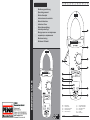
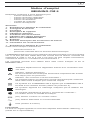
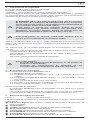
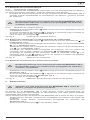
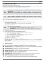
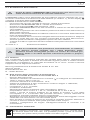
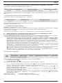
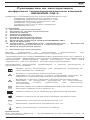
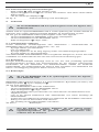
Bild 1: Gerätefrontseite
Fig. 1: Front tester panel
Fig. 1: Panneau avant de l‘appareil
Fig. 1: Parte frontal del equipo
obr. 1: Přední strana přístroje
ill. 1: Lato anteriore apparecchio
Fig. 1: Voorzijde van het apparaat
Rys. 1 Panel przedni przyrządu
рис. 1. Вид спереди.
Fig. 1: Framsida
Resim 1: Cihaz önyüzü
D F E I S

12/ 2005
BENNING CM 6
D F E I S
12/ 2005
BENNING CM 6
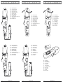
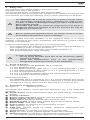
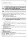
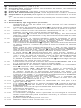
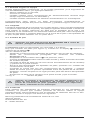
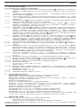
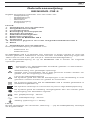
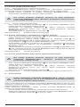
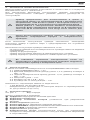
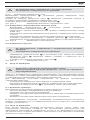
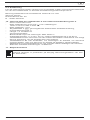
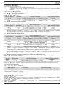
Bild 2: Gleichspannungsmessung
Fig. 2: Direct voltage measurement
Fig. 2: Mesure de tension continue
Fig. 2: Medición de tensión contínua
obr. 2: Měření stejnosměrného napětí
ill. 2: Misura tensione continua
Fig. 2: Meten van gelijkspanning
Rys.2: Pomiar napięcia stałego
рис. 2. Измерение напряжения постоянного тока
Fig. 2: Likspänningsmätning
Resim 2: Doğru Gerilim Ölçümü
Bild 3: Wechselspannungsmessung
Fig. 3: Alternating voltage measurement
Fig. 3: Mesure de tension alternative
Fig. 3: Medición de tensión alterna
obr. 3: Měření střídavého napětí
ill. 3: Misura tensione alternata
Fig. 3: Meten van wisselspanning
Rys.3: Pomiar napięcia przemiennego
рис. 3. Измерение напряжения переменного тока
Fig. 3: Växelspänningsmätning
Resim 3: Alternatif Gerilim Ölçümü
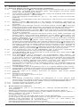
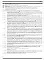
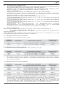
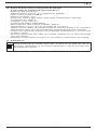
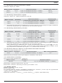
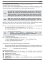
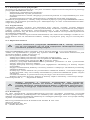
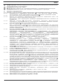
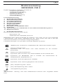
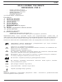
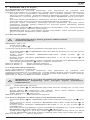
Bild 5: Widerstandsmessung
Fig. 5: Resistance measurement
Fig. 5: Mesure de résistance
Fig. 5: Medición de resistencia
obr. 5: Měření odporu
ill. 5: Misura di resistenza
Fig. 5: Weerstandsmeting
Rys.5: Pomiar rezystancji
рис. 5. Измерение сопротивления
Fig. 5: Resistansmätning
Resim 5: Direnç Ölçümü
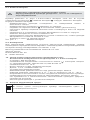
Bild 4: Wechselstrommessung
Fig. 4: AC current measurement
Fig. 4: Mesure de courant alternatif
Fig. 4: Medición de corriente alterna
obr. 4: Měření střídavého proudu
ill. 4:
Misura corrente alternata
Fig. 4: Meten van wisselstroom
Rys.4: Pomiar prądu przemiennego
рис. 4. Измерение величины переменного тока
Fig. 4: Växelströmsmätning
Resim 4: Alternatif Akım Ölçümü
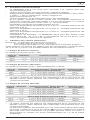
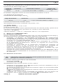
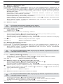
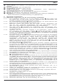
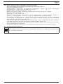
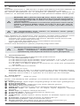
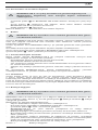
Bild 7: Batteriewechsel
Fig. 7: Battery replacement
Fig. 7: Remplacement de la pile
Fig. 7: Cambio de batería
obr. 7: Výměna baterií
ill. 7: Sostituzione batterie
Fig. 7: Vervanging van de batterijen
Rys.7: Wymiana baterii
рис. 7. Замена батареи
Fig. 7: Batteribyte
Resim 7: Batarya Değişimi
Bild 6: Frequenzmessung
Fig. 6: Frequency measurement
Fig. 6: Mesure de fréquence
Fig. 6: Medición de frecuencia
obr. 6: Měření frekvence
ill. 6: Misura di frequenza
Fig. 6: Frequentiemeting
Rys.6: Pomiar częstotliwości
рис. 6. Измерение частоты
Fig. 6: Frekvensmätning
Resim 6: Frekans Ölçümü
D F E I S
12/ 2005
BENNING CM 6
D F E I S

12/ 2005
BENNING CM 6
1
D
Bedienungsanleitung
BENNING CM 6
Digital-Stromzangen-Multimeter zur
- Gleichspannungsmessung
- Wechselspannungsmessung
- Wechselstrommessung
- Widerstandsmessung
- Durchgangsprüfung
- Frequenzmessung
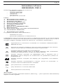
Inhaltsverzeichnis
1. Benutzerhinweise
2. Sicherheitshinweise
3. Lieferumfang
4. Gerätebeschreibung
5. Allgemeine Angaben
6. Umgebungsbedingungen
7. Elektrische Angaben
8. Messen mit dem BENNING CM 6
9. Instandhaltung
10. Technische Daten des Messzubehörs
11. Umweltschutz
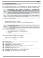
1. Benutzerhinweise
Diese Bedienungsanleitung richtet sich an
- Elektrofachkräfte und
- elektrotechnisch unterwiesene Personen
Das BENNING CM 6 ist zur Messung in trockener Umgebung vorgesehen. Es
darf nicht in Stromkreisen mit einer höheren Nennspannung als 1000 V DC
und 750 V AC eingesetzt werden (Näheres hierzu im Abschnitt 6. „Umgebungs-
bedingungen“).
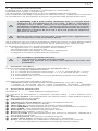
In der Bedienungsanleitung und auf dem BENNING CM 6 werden folgende
Symbole verwendet:
Anlegen um GEFÄHRLICHE AKTIVE Leiter oder Abnehmen von
diesen ist zugelassen.
Warnung vor elektrischer Gefahr!
Steht vor Hinweisen, die beachtet werden müssen, um Gefahren für
Menschen zu vermeiden.
Achtung Dokumentation beachten!
Das Symbol gibt an, dass die Hinweise in der Bedienungsanleitung
zu beachten sind, um Gefahren zu vermeiden.
Dieses Symbol auf dem BENNING CM 6 bedeutet, dass das
BENNING CM 6 schutzisoliert (Schutzklasse II) ausgeführt ist.
Dieses Symbol erscheint in der Anzeige für eine entladene
Batterie.
Dieses Symbol kennzeichnet den Bereich „Durchgangsprüfung“.
Der Summer dient der akustischen Ergebnisausgabe.
(DC) Gleich- Spannung oder Strom.
(AC) Wechsel- Spannung oder Strom.
Erde (Spannung gegen Erde).
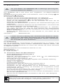
Hinweis
Nach Entfernen des Klebeschildes „Warnung...“ (auf dem Batteriedeckel) er-
scheint der englische Text!

12/ 2005
BENNING CM 6
2
D
2. Sicherheitshinweise
Das Gerät ist gemäß
DIN VDE 0411 Teil 1/ EN 61010-1
gebaut und geprüft und hat das Werk in einem sicherheitstechnisch einwand-
freien Zustand verlassen.
Um diesen Zustand zu erhalten und einen gefahrlosen Betrieb sicherzustellen,
muss der Anwender die Hinweise und Warnvermerke beachten, die in dieser
Anleitung enthalten sind.
Das BENNING CM 6 darf nur in Stromkreisen der Überspan-
nungskategorie III mit max. 1000 V Leiter gegen Erde benutzt
werden oder Überspannungskategorie IV mit 600 V Leiter ge-
gen Erde benutzt werden.
Beachten Sie, dass Arbeiten an spannungsführenden Teilen
und Anlagen grundsätzlich gefährlich sind. Bereits Spannun-
gen ab 30 V AC und 60 V DC können für den Menschen lebens-
gefährlich sein.
Vor jeder Inbetriebnahme überprüfen Sie das Gerät und die
Leitungen auf Beschädigungen.
Ist anzunehmen, dass ein gefahrloser Betrieb nicht mehr möglich ist, ist das
Gerät außer Betrieb zu setzen und gegen unbeabsichtigten Betrieb zu sichern.
Es ist anzunehmen, dass ein gefahrloser Betrieb nicht mehr möglich ist,
-
wenn das Gerät oder die Messleitungen sichtbare Beschädigungen aufweisen,
- wenn das Gerät nicht mehr arbeitet,
- nach längerer Lagerung unter ungünstigen Verhältnissen,
- nach schweren Transportbeanspruchungen.
Um eine Gefährdung auszuschließen
- berühren Sie die Messleitungen nicht an den blanken
Messspitzen,
- stecken Sie die Messleitungen in die entsprechend gekenn-
zeichneten Messbuchsen am Multimeter
3. Lieferumfang
Zum Lieferumfang des BENNING CM 6 gehören:
3.1 ein Stück BENNING CM 6,
3.2 ein Stück Sicherheitsmessleitung, rot (L = 1,4 m; Spitze Ø = 4 mm),
3.3 ein Stück Sicherheitsmessleitung, schwarz (L = 1,4 m; Spitze Ø = 4 mm),
3.4 ein Stück Kompakt-Schutztasche,
3.5 zwei 1,5-V-Mignon-Batterien zur Erstbestückung im Gerät eingebaut,
3.6 eine Bedienungsanleitung.
Hinweis auf Verschleißteile:
- Das BENNING CM 6 wird durch zwei eingebaute 1,5-V-Mignon-Batterie
(IEC LR 06) gespeist.
- Die oben genannten Sicherheitsmessleitungen ATL-2 (geprüftes Zubehör)
entsprechen CAT III 1000 V und sind für einen Strom von 10 A zugelas-
sen.
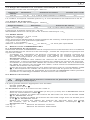
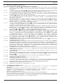
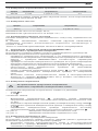
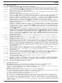
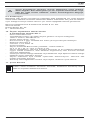
4. Gerätebeschreibung
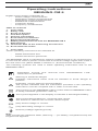
siehe Bild 1: Gerätefrontseite
Die in Bild 1 angegebenen Anzeige- und Bedienelemente werden wie folgt
bezeichnet:
Digitalanzeige, für den Messwert, die Bargraphanzeige und die Anzeige
der Bereichsüberschreitung
Polaritätsanzeige,
Batterieanzeige, erscheint bei entladener Batterie,
Taste (gelb), Displaybeleuchtung,
HOLD-Taste, Speicherung des angezeigten Messwertes,
MIN/MAX-Taste, Speicherung des höchsten und niedrigsten Messwertes,
Taste-PEAK, Spitzenwertspeicherung,
Drehschalter, für Wahl der Messfunktion,
Buchse (positive1), für V und Ω,
COM-Buchse, gemeinsame Buchse für Spannungs-, Widerstandsmessungen
und Durchgangsprüfung,

12/ 2005
BENNING CM 6
3
D
Öffnungshebel, zum Öffnen und Schließen der Stromzange,
Stromzangenwulzt, schützt vor Leiterberührung
Messzange, zum Umfassen des einadrigen stromdurchflossenen Leiters,
1) Hierauf bezieht sich die automatische Polaritätsanzeige für Gleichspannung
5. Allgemeine Angaben
5.1 Allgemeine Angaben zum Stromzangen-Multimeter
5.1.1 Die Digitalanzeige ist als 3 ¾-stellige Flüssigkristallanzeige
mit 14 mm Schrifthöhe mit Dezimalpunkt ausgeführt. Der größte
Anzeigewert ist 4000.
5.1.2 Die Polaritätsanzeige wirkt automatisch. Es wird nur eine Polung
entgegen der Buchsendefinition mit „-“ angezeigt.
5.1.3 Die Bereichsüberschreitung wird mit „0L“ oder „- 0L“ und teilweise einer
akustischen Warnung angezeigt.
Achtung, keine Anzeige und Warnung bei Überlast!
5.1.4 Taste (gelb) schaltet die Beleuchtung des Displays an. Ausschaltung
durch erneute Tastenbetätigung bzw. automatisch nach 60 Sekunden.
5.1.5 Messwertspeicherung „HOLD“: Durch Betätigen der Taste „HOLD“
lässt sich das Messergebnis speichern. Im Display wird gleichzeitig das
Symbol „HOLD“ eingeblendet. Erneutes Betätigen der Taste schaltet in
den Messmodus zurück.
5.1.6 Die MIN/MAX-Tastenfunktion erfasst und speichert automatisch den
höchsten und niedrigsten Messwert. Durch Tastenbetätigung werden
folgende Werte angezeigt:
„MAX“ zeigt den gespeicherten höchsten und „MIN“ den niedrigsten
Wert an. Die fortlaufende Erfassung des MAX-/ MIN-Wertes kann
durch Betätigung der Taste „HOLD“ gestoppt, bzw. gestartet werden.
Durch längeren Tastendruck (2 Sekunden) auf die Taste „MIN/MAX“
wird in den Normalmodus zurückgeschaltet.
5.1.7 Die Taste PEAK (Spitzenwertspeicherung) erfasst und speichert
den positiven und negativen Spitzen-/ Scheitelwert in der Funktion V
AC und A AC. Betätigen sie zu Beginn der Messung die Taste PEAK
für ca. 3 Sekunden um die Messgenauigkeit zu erhöhen und das
BENNING CM 6 abzugleichen. Durch Tastenbetätigung werden die
Werte von „PMAX“ oder „PMIN“ im Display angezeigt. Ein längerer
Tastendruck (2 Sekunden) auf die Taste PEAK-Taste schaltet in den
Normalmodus zurück.
5.1.8 Die Messrate des BENNING CM 6 beträgt nominal 1,5 Messungen pro
Sekunde für die Digitalanzeige.
5.1.9 Das BENNING CM 6 wird durch den Drehschalter ein- oder ausge-
schaltet. Ausschaltstellung „OFF“.
5.1.10 Das BENNING CM 6 schaltet sich nach ca. 30 Minuten selbsttätig ab
(APO, Auto-Power-Off). Es schaltet sich wieder ein, wenn eine Taste
oder der Drehschalter betätigt wird. Ein Summerton signalisiert die
selbsttätige Abschaltung des Gerätes. Die automatische Abschaltung
lässt sich deaktivieren, indem sie eine Taste (außer Taste „HOLD“)
betätigen und gleichzeitig das BENNING CM 6 aus der Schaltstellung
„OFF“ einschalten.
5.1.11 Temperaturkoeffizient des Messwertes: 0,2 x (angegebene
Messgenauigkeit)/ °C < 18 °C oder > 28 °C, bezogen auf den Wert bei
der Referenztemperatur von 23 °C.
5.1.12 Das BENNING CM 6 wird durch zwei 1,5-V-Mignon-Batterien gespeist
(IEC LR 06).
5.1.13
Wenn die Batteriespannung unter die vorgesehene Arbeitsspannung des
BENNING CM 6 sinkt, erscheint in der Anzeige ein Batteriesymbol .
5.1.14 Die Lebensdauer einer Batterie beträgt etwa 600 Stunden
(Alkalibatterie).
5.1.15 Geräteabmessungen:
(L x B x H) = 275 x 105 x 47 mm
Gerätegewicht:
534 g
5.1.16 Die Sicherheitsmessleitungen sind in 4 mm-Stecktechnik ausgeführt.
Die mitgelieferten Sicherheitsmessleitungen sind ausdrücklich für die
Nennspannung und dem Nennstrom des BENNING CM 6 geeignet.
5.1.17 Größte Zangenöffnung: 53 mm
5.1.18 Größter Leitungsdurchmesser: 51 mm
6. Umgebungsbedingungen
- Das BENNING CM 6 ist für Messungen in trockener Umgebung vor-
gesehen,
- Barometrische Höhe bei Messungen: Maximal 2000 m,
- Überspannungskategorie/ Aufstellungskategorie: IEC 60664-1/ IEC 61010-
1 (2001) → 600 V Kategorie IV; 1000 V Kategorie III,

12/ 2005
BENNING CM 6
4
D
- Verschmutzungsgrad: 2,
- Schutzart: IP 30 (DIN VDE 0470-1 IEC/ EN 60529)
3 - erste Kennziffer: Schutz gegen Zugang zu gefährlichen Teilen und
Schutz gegen feste Fremdkörper, > 2,5 mm Durchmesser
0 - zweite Kennziffer: Kein Wasserschutz,
- Arbeitstemperatur und relative Luftfeuchte:
Bei Arbeitstemperatur von 0 °C bis 30 °C: relative Luftfeuchte kleiner 80 %,
Bei Arbeitstemperatur von 31 °C bis 40 °C: relative Luftfeuchte kleiner 75 %,
Bei Arbeitstemperatur von 41 °C bis 50 °C: relative Luftfeuchte kleiner 45 %,
- Lagerungstemperatur: Das BENNING CM 6 kann bei Temperaturen von
- 20 °C bis + 60 °C (Luftfeuchte 0 bis 80 %) gelagert werden. Dabei ist die
Batterie aus dem Gerät herauszunehmen.
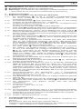
7. Elektrische Angaben
Bemerkung: Die Messgenauigkeit wird angegeben als Summe aus
- einem relativen Anteil des Messwertes und
- einer Anzahl von Digit (d.h. Zahlenschritte der letzten Stelle).
Diese Messgenauigkeit gilt bei Temperaturen von 18 °C bis 28 °C und einer
relativen Luftfeuchtigkeit kleiner 80 %.
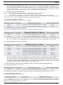
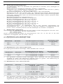
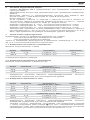
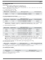
7.1 Gleichspannungsbereiche
Der Eingangswiderstand beträgt 1 MΩ
Messbereich Auflösung Messgenauigkeit Überlastschutz
400 V 0,1 V ± (0,7 % des Messwertes + 2 Digit) 750 Veff
1000 V 1 V ± (0,7 % des Messwertes + 2 Digit) 750 Veff
7.2 Wechselspannungsbereiche
Der Eingangswiderstand beträgt 1 MΩ parallel 100 pF.
Messbereich Auflösung Messgenauigkeit *1
im Frequenzbereich 50 Hz - 500 Hz
Überlastschutz
400 V 0,1 V ± (1 % des Messwertes + 2 Digit) 750 Veff
750 V 1 V ± (1 % des Messwertes + 2 Digit) 750 Veff
*1 Der Messwert wird durch Mittelwertgleichrichtung gewonnen und als
Effektivwert angezeigt. Seine Kalibrierung ist auf sinusförmige Kurvenform
abgestimmt.
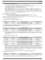
7.3 Wechselstrombereiche
Messbereich Auflösung
Messgenauigkeit *1
im Frequenzbereich 50 Hz - 60 Hz
Überlastschutz
60 A 0,1 A ± (1,9 % des Messwertes + 7 Digit) 1000 Aeff
400 A 0,1 A ± (1,9 % des Messwertes + 5 Digit) 1000 Aeff
1000 A 1 A ± (1,9 % des Messwertes + 5 Digit) 1000 Aeff
im Frequenzbereich 61 Hz - 400 Hz
400 A 0,1 A ± (2,5 % des Messwertes + 7 Digit) 1000 Aeff
1000 A 1 A ± (2,5 % des Messwertes + 7 Digit) 1000 Aeff
*1 Der Messwert wird durch Mittelwertgleichrichtung gewonnen und als Effektivwert
angezeigt. Seine Kalibrierung ist auf sinusförmige Kurvenform abgestimmt.
Die angegeben Genauigkeit ist spezifiziert für Leiter die mit der Messzange
mittig umfasst werden (siehe Bild 4 Wechselstrommessung). Für Leiter
die nicht mittig umfasst werden, muss ein zusätzlicher Fehler von 1 % des
Anzeigewertes berücksichtigt werden.
7.4 Widerstandsbereich und akustische Durchgangsprüfung
Überlastschutz: 600 Veff
Messbereich Auflösung
Messgenauigkeit Max. Leerlaufspannung
400 Ω 0,1 Ω ± (1 % des Messwertes + 3 Digit) 3 V
Der eingebaute Summer ertönt bei einem Widerstand R kleiner 30 Ω.

12/ 2005
BENNING CM 6
5
D
7.5 Frequenzbereiche
Überlastschutz: 1000 Aeff
Messbereich Auflösung
Messgenauigkeit
400 Hz 1 Hz ± (1 % des Messwertes + 2 Digit)
Minimale Eingangsfrequenz: 20 Hz
Minimale Empfindlichkeit: 3 Aeff
7.6 PEAK HOLD
Messbereiche: V AC, A AC
Kopplungsart: AC
In der PEAK-HOLD-Funktion (Spitzenwertspeicherung) muss zu der spezifizier-
ten Genauigkeit ein zusätzlicher Fehler berücksichtigt werden:
+ (± 3 % + 10 Digit)
Messwerte: > 750 VSpitze bzw. 800 ASpitze sind nicht spezifiziert
8. Messen mit dem BENNING CM 6
8.1 Vorbereiten der Messung
Benutzen und lagern Sie das BENNING CM 6 nur bei den angegebenen
Lager- und Arbeitstemperaturbedingungen, vermeiden Sie dauernde Sonnen-
einstrahlung.
- Angaben von Nennspannung und Nennstrom auf den Sicherheitsmess-
leitungen überprüfen. Die zum Lieferumfang gehörenden Sicherheits-
messleitungen entsprechen in Nennspannung und Nennstrom dem
BENNING CM 6.
- Isolation der Sicherheitsmessleitungen überprüfen. Wenn die Isolation
beschädigt ist, sind die Sicherheitsmessleitungen sofort auszusondern.
- Sicherheitsmessleitungen auf Durchgang prüfen. Wenn der Leiter in der
Sicherheitsmessleitung unterbrochen ist, sind die Sicherheitsmessleitungen
sofort auszusondern.
- Bevor am Drehschalter eine andere Funktion gewählt wird, müssen die
Sicherheitsmessleitungen von der Messstelle getrennt werden.
- Starke Störquellen in der Nähe des BENNING CM 6 können zu instabiler
Anzeige und zu Messfehlern führen.
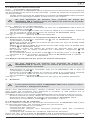
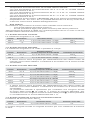
8.2 Spannungsmessung
Maximale Spannung gegen Erdpotential beachten!
Elektrische Gefahr!
Die höchste Spannung, die an den Buchsen,
- COM-Buchse
- Buchse für V und Ω
des BENNING CM 6 gegenüber Erde liegen darf, beträgt 1000 V.
- Mit dem Drehschalter die gewünschte Funktion (V AC) oder (V DC) am
BENNING CM 6 wählen.
- Die schwarze Sicherheitsmessleitung mit der COM-Buchse am
BENNING CM 6 kontaktieren.
- Die rote Sicherheitsmessleitung mit der Buchse für V und am
BENNING CM 6 kontaktieren.
- Die Sicherheitsmessleitungen mit den Messpunkten kontaktieren, Messwert
an der Digitalanzeige am BENNING CM 6 ablesen.
siehe Bild 2: Gleichspannungsmessung
siehe Bild 3: Wechselspannungsmessung
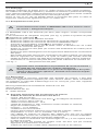
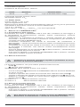
8.3 Wechselstrommessung
8.3.1 Vorbereiten der Messungen
Benutzen und lagern Sie das BENNING CM 6 nur bei den angegebe-
nen Lager- und Arbeitstemperaturbedingungen, vermeiden Sie dauernde
Sonneneinstrahlung.
- Starke Störquellen in der Nähe der BENNING CM 6 können zu instabiler
Anzeige und zu Messfehlern führen.
Keine Spannung an die Ausgangskontakte des BENNING CM 6
legen! Entfernen Sie eventuell die angeschlossenen Sicher-
heitsmessleitungen.

12/ 2005
BENNING CM 6
6
D
8.3.2 Wechselstrommessung
- Mit dem Drehschalter die gewünschte Funktion (A AC) am BENNING CM 6
wählen.
- Öffnungshebel betätigen, einadrigen, stromführenden Leiter mittig mit
der Zange des BENNING CM 6 umfassen.
- Die Digitalanzeige ablesen.
siehe Bild 4: Wechselstrommessung
8.4 Widerstandsmessung und akustische Durchgangsprüfung
- Mit dem Drehschalter die gewünschte Funktion ( ) am BENNING CM 6
wählen.
- Die schwarze Sicherheitsmessleitung mit der COM-Buchse am
BENNING CM 6 kontaktieren.
Die rote Sicherheitsmessleitung mit der Buchse für V und Ω am
BENNING CM 6 kontaktieren.
- Die Sicherheitsmessleitungen mit den Messpunkten kontaktieren, den
Messwert an der Digitalanzeige am BENNING CM 6 ablesen.
- Unterschreitet der Leitungswiderstand zwischen der COM-Buchse und
der Buchse für V und Ω 30 Ω, ertönt im BENNING CM 6 der eingebaute
Summer.
siehe Bild 5: Widerstandsmessung
8.5 Frequenzmessung über Strommesszange
Keine Spannung an die Ausgangskontakte des BENNING CM 6
legen! Entfernen Sie eventuell die angeschlossenen Sicher-
heitsmessleitungen.
- Mit dem Drehschalter die gewünschte Funktion (Hz) am BENNING CM 6
wählen.
- Öffnungshebel betätigen, einadrigen, stromführenden Leiter mittig mit
der Zange des BENNING CM 6 umfassen.
- Die Digitalanzeige ablesen.
siehe Bild 6: Frequenzmessung über Strommesszange
9. Instandhaltung
Vor dem Öffnen das BENNING CM 6 unbedingt spannungsfrei
machen! Elektrische Gefahr!
Die Arbeit am geöffneten BENNING CM 6 unter Spannung ist ausschließ-
lich Elektrofachkräften vorbehalten, die dabei besondere Maßnahmen zur
Unfallverhütung treffen müssen.
So machen Sie das BENNING CM 6 spannungsfrei, bevor Sie das Gerät
öffnen:
- Entfernen Sie zuerst beide Sicherheitsmessleitungen vom Messobjekt.
- Entfernen Sie dann beide Sicherheitsmessleitungen vom BENNING CM 6.
- Schalten Sie den Drehschalter in die Schaltstellung „OFF“.
9.1 Sicherstellen des Gerätes
Unter bestimmten Voraussetzungen kann die Sicherheit im Umgang mit dem
BENNING CM 6 nicht mehr gewährleistet sein; zum Beispiel bei:
- Sichtbaren Schäden am Gehäuse,
- Fehlern bei Messungen,
- Erkennbaren Folgen von längerer Lagerung unter unzulässigen
Bedingungen und
- Erkennbaren Folgen von außerordentlicher Transportbeanspruchung.
In diesen Fällen ist das BENNING CM 6 sofort abzuschalten, von den
Messstellen zu entfernen und gegen erneute Nutzung zu sichern.
9.2 Reinigung
Reinigen Sie das Gehäuse äußerlich mit einem sauberen und trockenen Tuch
(Ausnahme spezielle Reinigungstücher). Verwenden Sie keine Lösungs- und/
oder Scheuermittel, um das Gerät zu reinigen. Achten Sie unbedingt darauf,
dass das Batteriefach und die Batteriekontakte nicht durch auslaufendes
Batterie-Elektrolyt verunreinigt werden.
Falls Elektrolytverunreinigungen oder weiße Ablagerungen im Bereich der
Batterie oder des Batteriegehäuses vorhanden sind, reinigen Sie auch diese
mit einem trockenen Tuch.

12/ 2005
BENNING CM 6
7
D
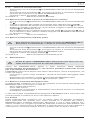
9.3 Batteriewechsel
Vor dem Öffnen das BENNING CM 6 unbedingt spannungsfrei
machen! Elektrische Gefahr!
Das BENNING CM 6 wird durch zwei eingebaute 1,5-V-Mignon-Batterien
gespeist.
Ein Batteriewechsel (siehe Bild 7) ist erforderlich, wenn in der Anzeige das
Batteriesymbol erscheint.
So wechseln Sie die Batterie:
- Entfernen Sie die Sicherheitsmessleitungen vom Messkreis.
- Entfernen Sie die Sicherheitsmessleitungen vom BENNING CM 6.
- Bringen Sie den Drehschalter in die Schaltstellung „OFF“.
- Legen Sie das BENNING CM 6 auf die Frontseite und lösen Sie die
Schraube vom Batteriedeckel.
- Heben Sie den Batteriedeckel (im Bereich der Gehäusevertiefungen) vom
Unterteil ab.
- Heben Sie die entladenen Batterien aus dem Batteriefach, und nehmen Sie
die Batteriezuleitungen von der Batterie ab.
- Die neuen Batterien sind mit den Batteriezuleitungen zu verbinden,
und ordnen Sie diese so, dass sie nicht zwischen den Gehäuseteilen
gequetscht werden. Legen Sie dann die Batterien an die dafür vorgesehene
Stelle im Batteriefach.
- Rasten Sie den Batteriedeckel an das Unterteil an, und ziehen Sie die
Schraube an.
siehe Bild 7: Batteriewechsel
Leisten Sie Ihren Beitrag zum Umweltschutz! Batterien dürfen
nicht in den Hausmüll. Sie können bei einer Sammelstelle für
Altbatterien bzw. Sondermüll abgegeben werden. Informieren
Sie sich bitte bei Ihrer Kommune.
9.4 Kalibrierung
Um die angegebenen Genauigkeiten der Messergebnisse zu erhalten, muss
das Gerät regelmäßig durch unseren Werksservice kalibriert werden. Wir
empfehlen ein Kalibrierintervall von einem Jahr. Senden Sie hierzu das Gerät
an folgende Adresse:
Benning Elektrotechnik & Elektronik GmbH & Co. KG
Service Center
Robert-Bosch-Str. 20
D - 46397 Bocholt
10. Technische Daten des Messzubehörs
4 mm Sicherheitsmessleitung ATL 2
- Norm: EN 61010-031,
- Maximale Bemessungsspannung gegen Erde ( ) und Messkategorie:
1000 V CAT III, 600 V CAT IV,
- Maximaler Bemessungsstrom: 10 A,
- Schutzklasse II (), durchgängige doppelte oder verstärkte Isolierung,
- Verschmutzungsgrad: 2,
- Länge: 1,4 m, AWG 18,
- Umgebungsbedingungen:
Barometrische Höhe bei Messungen: Maximal 2000 m,
Temperatur: 0 °C bis + 50 °C, Feuchte 50 % bis 80 %
- Verwenden Sie die Messleitungen nur im einwandfreien Zustand und
entsprechend dieser Anleitung, da ansonsten der vorgesehene Schutz
beeinträchtigt sein kann.
- Sondern Sie die Messleitung aus, wenn die Isolierung beschädigt ist oder
eine Unterbrechung in Leitung/ Stecker vorliegt.
- Berühren Sie die Messleitung nicht an den blanken Kontaktspitzen. Fassen
Sie nur den Handbereich an!
- Stecken Sie die abgewinkelten Anschlüsse in das Prüf- oder Messgerät.
11. Umweltschutz
Bitte führen Sie das Gerät am Ende seiner Lebensdauer den zur
Verfügung stehenden Rückgabe- und Sammelsystemen zu.

12/ 2005
BENNING CM 6
8
Operating instructions
BENNING CM 6
Digital current probe multimeter for
- Direct voltage measurements
- Alternating voltage measurements
- Alternating current measurement
- Resistance measurements
- Continuity testing
- Frequency measurement
Table of contents
1. User notes
2. Safety note
3. Scope of delivery
4. Unit description
5. General information
6. Environment conditions:
7. Electrical specifications
8. Making measurements with the BENNING CM 6
9. Maintenance
10. Technical data of the measuring accessories
11. Environmental notice
1. User notes
These operating instructions are intended for
- skilled electricians and
- trained electronics personnel.
The BENNING CM 6 is intended for making measurements in dry environment.
It must not be used in power circuits with a nominal voltage higher than 1000 V
DC and 750 V AC (More details in Section 6. „Environmental conditions”).
The following symbols are used in these operating instructions and on the
BENNING CM 6:
Application around and removal from HAZARDOUS LIVE
conductors is permitted.
Warning of electrical danger!
Indicates instructions which must be followed to avoid danger to
persons.
Important, comply with the documentation!
The symbol indicates that the information provided in the operating
instructions must be complied with in order to avoid risks.
This symbol on the BENNING CM 6 means that the BENNING CM 6
is totally insulated (protection class II).
This symbol appears in the display to indicate a discharged battery.
This symbol designates the „continuity test” range.
The buzzer is used for the acoustic result output.
(DC) Direct voltage or current.
(AC) Alternating voltage or current.
Ground (Voltage against ground).
Note
After unmark the adhesive label „Warnung...“ (on battery compartment lid) the
English text appears.

12/ 2005
BENNING CM 6
9
2. Safety note
The instrument is built and tested in accordance with
DIN VDE 0411 part 1/ EN 61010-1
and has left the factory in perfectly safe technical state.
To maintain this state and ensure safe operation of the appliance tester, the user
must observe the notes and warnings given in these instructions at all times.
The BENNING CM 6 may be used only in power circuits within
the overvoltage category III with a conductor for 1000 V max.
to earth, or within overvoltage category IV with a conductor for
600 V against ground.
Remember that work on electrical components of all kinds is
dangerous. Even low voltages of 30 V AC and 60 V DC may be
dangerous to human life.
Before starting the appliance tester up, always check it as well
as all cables and wires for signs of damage.
Should it appear that safe operation of the appliance tester is no longer
possible, it should be shut down immediately and secured to prevent it being
switched on accidentally.
It may be assumed that safe operation is no longer possible:
- if the instrument or the measuring cables show visible signs of damage, or
- if the appliance tester no longer functions, or
- after long periods of storage under unfavourable conditions, or
- after being subjected to rough transport.
In order to avoid danger,
- do not touch the bare prod tips of the measuring cables
measuring probes,
- insert the measurement lines in the appropriately
designated measuring sockets on the multimeter
3. Scope of delivery
The scope of delivery for the BENNING CM 6 comprises:
3.1 One BENNING CM 6,
3.2
One safety measuring cable, red (L = 1.4 m; prod tip diameter = 4 mm)
3.3
One safety measuring cable, black (L = 1.4 m; prod tip diameter = 4 mm)
3.4 One compact protective pouch,
3.5 Two 1.5-V-Mignon-batteries fitted in the unit as original equipment,
3.6 One operating instructions manual
Parts subject to wear:
-
The BENNING CM 6 is supplied by two 1.5 V mignon batteries (IEC LR 06).
- The above-mentioned safety measuring cables ATL-2 (tested accessories)
correspond to CAT III 1000 V and are approved for a current of 10 A.
4. Description of appliance tester
See figure 1: Appliance front face
The display and operator control elements specified in Fig. 1 are designated
as follows:
Digital display, for the measurement value, bar graph display, overranging
display,
Polarity indication,
Battery status indication, appears when the battery is discharged,
Button (yellow), display lighting,
HOLD button, storage of the indicated measured value,
MIN/MAX button, storage of the highest and lowest measured values,
Button PEAK, peak value storage,
Rotary switch, for selecting the measurement function,
Jack (positive1), for V, Ω
COM jack, common socket for voltage, resistance measurement and
continuity testing,
Opening lever, for opening and closing the current probe,
Bulge of current probe, protects against contact with conductor,
Measuring pliers, for clamping on the single wire current-carrying conductor,
1) This is what the automatic polarity indication for DC voltage refers to

12/ 2005
BENNING CM 6
10
5. General information
5.1 General details on the current probe multimeter
5.1.1 The digital display is a 3¾-digit liquid crystal display with 14 mm high
numerals, complete with decimal point. The largest numerical value
which can be displayed is 4000.
5.1.2 The polarity indication is automatic. Only one polarity with respect to
the socket marked „-“ is indicated.
5.1.3 The overranging is indicated by „0L” or „- 0L” and, in part, an acoustic
warning.
Warning, no indication and prior warning in the event of an overload
condition!
5.1.4 Button (yellow) switches on the display illumination. Shutdown is
effected by a renewed press of the button or automatically after 60
seconds.
5.1.5
Measured value storage „HOLD”: Press the button „HOLD” to store the
measured result. At the same time, the display shows the symbol „HOLD”.
A renewed press of the button switches back into measuring mode.
5.1.6 The MIN/MAX button function inputs and stores automatically the
highest and lowest measured value . The following values are indicated
by button operation:
„MAX” indicates the stored maximum value, and „MIN” indicates the
lowest value. The continuous detection of the MAX-/ MIN value can
be stopped or started by pressing the button „HOLD” . Pressing the
button „MIN/MAX“ for an extended period of time (2 seconds) switches
back into normal mode.
5.1.7 The button PEAK (peak value storage) detects and stores the
positive and negative peak/ crest values in the function V AC and A AC.
At the start of the measurement, press the button PEAK for approx. 3
seconds in order to increase measurement precision and to fine-adjust
the BENNING CM 6. Pressing the button indicates the „PMAX” or
„PMIN” values in the display. Pressing the PEAK button for an extended
period of time (2 seconds) switches back into normal mode.
5.1.8 The measuring rate of the BENNING CM 6 amounts nominally to
1.5 measurements per second for the digital display.
5.1.9 The BENNING CM 6 is switched on and off with the rotary switch .
Shutdown position „OFF”.
5.1.10 The BENNING CM 6 switches off automatically after approx. 30
minutes (APO, Auto-Power-Off). It switches back on again if a button
or the rotary switch is operated. A buzzer sound signals the automatic
switchoff of the unit. The automatic switchoff can be deactivated by
pressing a button (except the button „HOLD”) and simultaneously
switching on the BENNING CM 6 from switch position „OFF”.
5.1.11 Temperature coefficient of the measured value: 0.2 x (stated measuring
precision)/ °C < 18 °C or > 28 °C, related to the value for the reference
temperature of 23° C.
5.1.12
The BENNING CM 6 is supplied by two 1.5 V mignon batteries (IEC LR 06).
5.1.13 If the battery voltage drops below the specified operating voltage of the
BENNING CM 6, then a battery symbol appears in the display.
5.1.14 The life span of a battery amounts to approx. 600 hours (alkali
battery).
5.1.15 Appliance dimensions:
(L x W x H) = 275 x 105 x 47 mm
Appliance weight:
534 g
5.1.16 The safety measuring cables are designed in 4 mm plug-in type
technology. The safety measuring cables supplied are expressly suited
for the rated voltage and the rated current of the BENNING CM 6.
5.1.17 Largest opening of pliers: 53 mm
5.1.18 Largest cable diameter: 51 mm
6. Environment conditions:
- The BENNING CM 6 is intended for making measurements in dry
environment.
- Maximum barometric elevation for making measurements: 2000 m,
- Overvoltage category/ Siting category: IEC 60664-1/ IEC 61010-1 (2001) →
600 V category IV; 1000 V category III,
- Contamination class: 2,
- Protection Class: IP 30 (DIN VDE 0470-1 IEC/ EN 60529)
IP 30 means: Protection against access to dangerous parts and protection
against solid impurities of a diameter > 2.5 mm, (3 - first index). No
protection against water, (0 - second index).
- Operating temperature and relative humidity:
For operating temperature from 0 °C to 30 °C: relative humidity less than 80 %

12/ 2005
BENNING CM 6
11
For operating temperatures from 31 °C to 40 °C: relative humidity less than 75 %
For operating temperature from 41 °C to 50 °C: relative humidity less than 45 %
- Storage temperature: The BENNING CM 6 can be stored at any temperature
in the range from - 20 °C to + 60 °C (relative humidity from 0 to 80 %). The
battery should be taken out of the instrument for storage.
7. Electrical specifications
Note: The measuring precision is specified as the sum of
- a relative fraction of the measured value and
- a number of digits (counting steps of the least significant digit).
This specified measuring precision is valid for temperatures in the range from
18 °C to 28 °C and relative humidity less than 80 %.
7.1 Direct voltage ranges
The input resistance amounts to 1 MΩ
Measuring range Resolution
Measuring precision Overload protection
400 V 0,1 V ± (0,7 % of the measuring value + 2 digit) 750 Veff
1000 V 1 V ± (0,7 % of the measuring value + 2 digit) 750 Veff
7.2 Alternating voltage ranges
The input resistance amounts to 1 MΩ in parallel 100 pF.
Measuring range Resolution
Measuring precision *1 within the
frequency range 50 Hz - 500 Hz Overload protection
400 V 0,1 V ± (1 % of the measuring value + 5 digit) 750 Veff
750 V 1 V ± (1 % of the measuring value + 5 digit) 750 Veff
*1
The measured value is obtained by mean value rectification and displayed
as r.m.s. value. Its calibration is matched to a sinus-shaped curve type.
7.3 Alternating current ranges
Measuring range Resolution Measuring precision *1 within the
frequency range 50 Hz - 60 Hz
Overload protection
60 A 0,1 A ± (1,9 % of the measuring value + 7 digit) 1000 Aeff
400 A 0,1 A ± (1,9 % of the measuring value + 5 digit) 1000 Aeff
1000 A 1 A ± (1,9 % of the measuring value + 5 digit) 1000 Aeff
within the frequency range 61 Hz - 400 Hz
400 A 0,1 A ± (2,5 % of the measuring value + 7 digit) 1000 Aeff
1000 A 1 A ± (2,5 % of the measuring value + 7 digit) 1000 Aeff
*1 The measured value is obtained by mean value rectification and displayed
as r.m.s. value. Its calibration is matched to a sinus-shaped curve type.
The stated precision is specified for conductors that are centrally clamped
by the current probe (see Fig. 4 alternating current measurement). For
conductors that are not centrally clamped, an additional error of 1 % of the
display value needs to be taken into account.
7.4 Resistance measuring range and acoustic continuity testing
Overload protection: 600 Veff
Measuring range Resolution Measuring precision
Max. idling voltage
400 Ω 0,1 Ω ± (0,7 % of the measuring value + 3 digit) 3 V
The built-in buzzer sounds in the case of a resistance R less than 30 Ω.
7.5 Frequency ranges
Overload protection: 1000 Aeff
Measuring range Resolution Measuring precision
400 Hz 1 Hz ± (0,1 % of the measuring value + 2 digit)
Minimum input frequency: 20 Hz
Minimum sensitivity: 3 Aeff

12/ 2005
BENNING CM 6
12
7.6 PEAK HOLD
Measuring ranges: V AC, A AC
Coupling type: AC
In the PEAK-HOLD function (peak value storage) an additional error needs to
be taken into account for the specified precision.
+ (± 3% + 10 digits)
Measurement values: > 750 VPeak or 800 APeak are not specified
8. Making measurements with the BENNING CM 6
8.1 Preparations for making measurements
Operate and store the BENNING CM 6 only at the specified storage and
operating temperatures conditions. Avoid continuous insulation.
- Check rated voltage and rated current details specified on the safety
measuring lines. The nominal voltage and current ratings of the safety
measuring cables included in the scope of delivery correspond to the
ratings of the BENNING CM 6.
- Check the insulation of the safety measuring cables. Discard the safety
measuring cables immediately if the insulation is damaged.
- Check safety measuring lines for continuity. If the conductor in the safety measuring
line is interrupted, the safety measuring line must be quarantined immediately.
- Before - at the rotary switch a different function is selected, the safety
measuring lines must be disconnected from the measuring point.
- Strong sources of interference in the vicinity of the BENNING CM 6 can lead
to unstable readings and measuring errors.
8.2 Voltage measuring
Do not exceed the maximum permitted voltage with respect to
earth potential! Electrical danger!
The highest voltage which may be applied to the jacks,
- COM socket
- jack for V, Ω
of the BENNING CM 6 against ground, amounts to 1000 V.
- Use the rotary switch to select the required function (V AC) or (V DC) on
the BENNING CM 6.
- The black safety measuring cable has to be contacted with the COM jack
on the BENNING CM 6.
- The red safety measuring cable has to be connected to the jack for V, Ω
on the BENNING CM 6.
- Bring the safety measuring lines into contact with the measuring points,
read off measured value on the digital display on the BENNING CM 6.
See figure 2: Direct voltage measurement
See figure 3: Alternating voltage measurement
8.3 Alternating current measurement
8.3.1 Preparations for making measurements
Operate and store the BENNING CM 6 only at the specified storage and
operating temperatures conditions. Avoid continuous insulation.
- Strong sources of interference in the vicinity of the BENNING CM 6 can lead
to unstable readings and measuring errors.
Do not apply any voltage to the output contacts of the
BENNING CM 6! Any possibly connected safety measuring
cables have to be removed.
8.3.2 Alternating current measurement
- Use the rotary switch to select the required function (A AC) on the
BENNING CM 6.
- Operate opening lever clamp single wire live conductor centrally by
means of the BENNING CM 6 pliers.
- Read off the digital display unit .
See figure 4: Alternating current measurement

12/ 2005
BENNING CM 6
13
8.4 Resistance measuring and acoustic continuity testing
- Use the rotary switch to select the required function ( ) on the
BENNING CM 6.
- The black safety measuring cable has to be contacted with the COM jack
on the BENNING CM 6. The red safety measuring cable has to be
connected to the jack for V, Ω on the BENNING CM 6.
- Bring the safety measuring lines into contact with the measuring points,
read off measured value on the digital display on the BENNING CM 6.
- If the conductor resistance between the COM jack and the jack for V, Ω
30 Ω, the fitted buzzer sounds on the BENNING CM 6.
See figure 5: Resistance measurements
8.5 Frequency measurement via current measuring pliers
Do not apply any voltage to the output contacts of the
BENNING CM 6! Any possibly connected safety measuring
cables have to be removed.
- Use the rotary switch to select the required function (Hz) on the
BENNING CM 6.
- Operate opening lever , clamp single wire live conductor centrally by
means of the BENNING CM 6 pliers.
- Read off the digital display unit .
See figure 6: Frequency measurement via current measuring pliers
9. Maintenance
Before opening the BENNING CM 6, make quite sure that it is
voltage free! Electrical danger!
Work on the opened BENNING CM 6 under voltage may be carried out only by
skilled electricians with special precautions for the prevention of accidents.
Make the BENNING CM 6 voltage free as follows before opening the
instrument:
- First remove the two safety measuring lines from the object to be
measured.
- Then disconnect the two safety measuring cables from the
BENNING CM 6
- Set rotary switch to switch position „OFF”.
9.1 Securing the instrument
Under certain circumstances safe operation of the BENNING CM 6 is no longer
ensured, for example in the case of:
- Visible damage of the casing.
- Incorrect measurement results.
- Recognisable consequences of prolonged storage under improper
conditions.
- Recognisable consequences of extraordinary transportation stress.
In such cases the BENNING CM 6 must be switched off immediately,
disconnected from the measuring points and secured to prevent further
utilisation.
9.2 Cleaning
Clean the casing externally with a clean dry cloth (exception: special cleaning
wipers). Avoid using solvents and/or scouring agents for cleaning the instrument.
It is important to make sure that the battery compartment and battery contacts
are not contaminated by leaking electrolyte.
If electrolyte contamination or white deposits are present in the region of the
batteries or battery casing, clean them too with a dry cloth.

12/ 2005
BENNING CM 6
14
9.3 Battery change
Before opening the BENNING CM 6, make quite sure that it is
voltage free! Electrical danger!
The BENNING CM 6 is fed by two 1.5-V mignon batteries.
A battery change (see Figure 7) is required, if the battery symbol appears.
Proceed as follows to replace the batteries:
- Disconnect the safety measuring cables from the measuring circuit.
- Disconnect the safety measuring cables from the BENNING CM 6
- Set the rotary switch to the switch setting ”OFF”.
- Lay the BENNING CM 6 face down and release the slot screws of the
battery compartment cover.
- Lift the battery compartment lid (in the housing recess area) from the bottom
section.
- Lift the discharged battery from the battery compartment and disconnect the
battery supply lines from the battery.
- The new batteries have to be connected to the battery supply lines, and
arrange these such that they are not crushed between the housing parts.
Then place the batteries into the battery compartment provided for this
purpose.
- Place the battery compartment cover onto the bottom part and tighten the
screw.
See figure 7: Battery replacement
Make your contribution to environmental protection! Do not
dispose of discharged batteries in the household garbage.
Instead, take them to a collecting point for discharged batteries
and special waste material. Please inform yourself in your
community.
9.4 Calibration
To maintain the specified precision of the measurement results, the instrument
must be recalibrated at regular intervals by our factory service. We recommend
a recalibration interval of one year. Send the appliance to the following
address:
Benning Elektrotechnik & Elektronik GmbH & CO. KG
Service Centre
Robert-Bosch-Str. 20
D - 46397 Bocholt
10. Technical data of the measuring accessories
4 mm Safety test leads ATL 2
- Standard: EN 61010-031,
- Maximum rated voltage to earth ( ) and measuring category:
1000 V CAT III, 600 V CAT IV,
- Maximum rated current: 10 A,
- Protective class II (), continuous double or reinforced insulation,
- Contamination class: 2,
- Length: 1.4 m, AWG 18,
- Environmental conditions:
Maximum barometric elevation for making measurements: 2000 m,
Temperatures: 0 °C to + 50 °C, humidity 50 % to 80 %
- Only use the test leads if in perfect condition and according to this manual,
since the protection provided could otherwise be impaired.
- Throw the test leads out if the insulation is damaged or if there is a break in
the cable/ plug.
- Do not touch the bare contact tips of the test leads. Only grab the area
appropriate for hands!
- Insert the angled terminals in the testing or measuring device.
11. Environmental notice
At the end of the product’s useful life, please dispose of it at
appropriate collection points provided in your country.

12/ 2005
BENNING CM 6
15
F
Notice d‘emploi
BENNING CM 6
Multimètre numérique à pince électrique pour
- mesure de tension continue
- mesure de tension alternative
- mesure de courant alternatif
- mesure de résistance
- contrôle de continuité
- mesure de fréquence
Sommaire
1. Remarques à l‘attention de l‘utilisateur
2. Consignes de sécurité
3. Fourniture
4. Description de l‘appareil
5. Indications générales
6. Conditions d‘environnement
7. Indication des valeurs électriques
8. Mesure avec le BENNING CM 6
9. Entretien
10. Données techniques des accessoires de mesure
11. Information sur l’environnement
1. Remarques à l‘attention de l‘utilisateur
Cette notice d‘emploi s‘adresse aux
- électrotechniciens et
- personnes instruites dans le domaine électrotechnique
Le BENNING CM 6 est conçu pour effectuer des mesures dans un environnement
sec. Il ne doit pas être utilisé dans des circuits dont la tension nominale est
supérieure à 1000 V CC et à 750 V CA (pour de plus amples informations,
consulter la section 6 « Conditions d‘environnement ».
Les symboles suivants sont utilisés dans cette notice d‘emploi et sur le
BENNING CM 6:
Permet le déplacement et l’application autours d’un conducteur actif
non isolé.
Attention ! Danger électrique !
Se trouve devant les remarques devant être respectées afin d‘éviter
tout risque pour les personnes.
Attention ! Se conformer à la documentation !
Ce symbole indique qu‘il faut tenir compte des remarques contenues
dans cette notice d‘emploi pour éviter les risques.
Ce symbole sur le BENNING CM 6 signifie que le BENNING CM 6
est doté d‘une isolation double (classe de protection II).
Ce symbole apparaît sur l‘affichage indiquant que la batterie est
déchargée.
Ce symbole caractérise la gamme « Contrôle de continuité ».
Le ronfleur fournit un résultat acoustique.
(CC) Tension continue ou courant continu.
(CA) Tension alternative ou courant alternatif.
Terre (tension à la terre).
Instructions
Le texte en anglais apparaît en enlevant l’étiquette autocollante «Warnung...»
(située sur le capot batterie).

12/ 2005
BENNING CM 6
16
F
2. Consignes de sécurité
Cet appareil a été fabriqué et contrôlé conformément à
DIN VDE 0411 Partie 1/ EN 61010-1
et a quitté les ateliers de production dans un état technique parfait.
Pour conserver cet état et garantir un service sans risques, l‘utilisateur doit se
conformer aux remarques et aux avertissements contenus dans cette notice
d‘utilisation.
Le BENNING CM 6 doit être utilisé uniquement dans des circuits
électriques de la catégorie de protection contre les surtensions
III avec des conducteurs de max. 1000 V raccordés à la terre ou
de la catégorie de protection contre les surtensions IV avec des
conducteurs de max. 600 V raccordés à la terre.
Veuillez noter que les travaux au niveau d‘éléments et
d‘installations conducteurs de tension sont toujours dangereux.
Déjà les tensions de 30 V CA et 60 V CC peuvent être mortelles.
Assurez-vous, avant chaque mise en marche, que l‘appareil et
les câbles ne sont pas détériorés.
Si l‘on considère que l‘utilisation sans risques n‘est plus possible, il faut mettre
l‘appareil hors service et le protéger contre toute utilisation involontaire.
Une utilisation sans risques n‘est plus possible
- quand l‘appareil ou les câbles de mesure présentent des détériorations
visibles,
- quand l‘appareil ne fonctionne plus,
- après un stockage prolongé dans de mauvaises conditions,
- après des conditions difficiles de transport.
Pour exclure tout danger,
- ne touchez pas les parties dénudées des câbles de mesure
au niveau des pointes de mesure,
- raccordez les câbles de mesure aux douilles de mesure
repérées correspondantes du multimètre
3. Fourniture
Font partie de la fourniture du BENNING CM 6 :
3.1 un BENNING CM 6,
3.2 un câble de mesure de sécurité, rouge (L = 1,4 m ; pointe Ø = 4 mm),
3.3 un câble de mesure de sécurité, noir (L = 1,4 m ; pointe Ø = 4 mm),
3.4 un étui compact de protection,
3.5 deux piles mignon rondes de 1,5 V montées initialement dans
l‘appareil,
3.6 une notice d‘emploi.
Remarque concernant les pièces d‘usure :
- Le BENNING CM 6 est alimenté par deux piles mignon rondes incorporées
de 1,5 V (IEC LR 06).
- Les câbles de mesure de sécurité ATL 2 (accessoires contrôlés) mentionnés
ci-dessus correspondent à CAT III 1000 V et sont homologués pour un
courant de 10 A.
4. Description de l‘appareil
voir fig. 1 : Partie avant de l‘appareil
Les éléments d‘affichage et de commande représentés à la fig. 1 sont les
suivants :
indicateur numérique pour la valeur mesurée, le barregraphe et l‘affichage
de dépassement de gamme
affichage de polarité,
indicateur de piles, apparaît quand le pile est déchargée,
touche (jaune), éclairage de visualisation,
touche HOLD, mémorisation de la valeur mesurée affichée,
touche MIN/MAX, mémorisation de la valeur mesurée maximum et
minimum,
touche PEAK, mémorisation de crêtes,
commutateur rotatif, pour la sélection de la fonction de mesure,
douille (positive1), pour V et Ω

12/ 2005
BENNING CM 6
17
F
douille COM, douille commune pour mesures de tension, de résistance et
pour contrôle de continuité,
levier, pour ouvrir et fermer la pince électrique,
Bourrelet de pince électrique, protège contre tout contact avec le
conducteur
pince de mesure pour saisir le câble à courant à un conducteur,
1) L‘affichage automatique de polarité de la tension continue se rapporte à cela.
5. Indications générales
5.1 Indications générales concernant le multimètre à pince électrique
5.1.1 L‘indicateur numérique est un indicateur ACL à 3¾ positions d‘une
hauteur de caractères de 14 mm et à virgule décimale. La plus grande
valeur affichée est 4000.
5.1.2 L‘affichage de la polarité a lieu automatiquement. Seule une polarité
contre la définition des douilles est indiquée par « - ».
5.1.3 Le dépassement de plage est indiquée par « 0L » ou « -0L » et,
partiellement, par un signal acoustique.
Attention : pas d‘affichage et d‘avertissement en cas de surcharge !
5.1.4 touche (jaune) sert à allumer l‘éclairage de la visualisation. Arrêt par
actionnement répété de la touche ou automatiquement au bout de 60
secondes.
5.1.5 Mémorisation des valeurs mesurées « HOLD »: On peut mémoriser le
résultat de la mesure en actionnant la touche « HOLD » . Le symbole
« HOLD » apparaît en même temps sur la visualisation. On retourne au
mode de mesure quand on actionne de nouveau la touche.
5.1.6 La touche de fonction MIN/MAX saisit et mémorise automatiquement
la valeur mesurée maximum et minimum. Les valeurs suivantes sont
affichées quand on actionne la touche :
« MAX » affiche la valeur maximum mémorisée et « MIN » la valeur
minimum mémorisée. On peut interrompre ou lancer la saisie continue
de la valeur MAX/MIN à l‘aide de la touche « HOLD » . Quand on
exerce une pression prolongée (2 secondes) sur la touche « MIN/
MAX », on retourne au mode normal.
5.1.7 La touche PEAK (mémorisation de crêtes) saisit et mémorise la
valeur maximum/de crête positive et négative dans la fonction V CA et
A CA. Au début de la mesure, actionnez la touche PEAK pendant
env. 3 secondes pour accroître la précision de mesure et syntoniser le
BENNING CM 6. Les valeurs « PMAX » ou « PMIN » sont affichées
sur la visualisation quand on actionne la touche. Quand on exerce une
pression prolongée (2 secondes) sur la touche PEAK , on retourne
au mode normal.
5.1.8 Le taux de mesure nominal du BENNING CM 6 est de 1,5 mesures par
seconde pour l‘indicateur numérique.
5.1.9 Le commutateur rotatif permet de mettre le BENNING CM 6 en et
hors circuit. Position d‘arrêt « OFF ».
5.1.10 Le BENNING CM 6 se déconnecte automatiquement au bout d‘env. 30
minutes (APO, Auto-Power-Off). Il se réenclenche quand on actionne
une touche ou le commutateur rotatif. Un signal sonore indique l‘arrêt
automatique de l‘appareil. On peut désactiver l‘arrêt automatique en
actionnant une touche (à l‘exception de la touche « HOLD ») et en
retirant simultanément le BENNING CM 6 de la position « OFF ».
5.1.11 Coefficient de température de la valeur mesurée : 0,2 x (précision de
mesure indiquée)/ °C < 18 °C ou > 28 °C, par rapport à la valeur de
température de référence de 23 °C.
5.1.12 Le BENNING CM 6 est alimenté par deux piles mignon rondes de 1,5 V
(IEC LR 06).
5.1.13 Quand la tension de pile tombe au-dessous de la tension de travail du
BENNING CM 6, un symbole de pile apparaît sur l‘affichage .
5.1.14 La longévité d‘une pile est d‘env. 600 heures (pile alcaline).
5.1.15 Dimensions de l‘appareil :
(long. x larg. x haut.) = 275 x 105 x 47 mm
Poids de l‘appareil :
534 g
5.1.16 Les câbles de mesure de sécurité sont dotés de fiches de 4 mm. Les
câbles de mesure de sécurité fournis conviennent explicitement pour la
tension nominale et le courant nominal du BENNING CM 6.
5.1.17 Ouverture maximum de pince : 53 mm
5.1.18 Diamètre maximum de câble : 51 mm

12/ 2005
BENNING CM 6
18
F
6. Conditions d‘environnement
- Le BENNING CM 6 est conçu pour procéder à la mesure dans des
environnements secs,
- hauteur barométrique pour les mesures : maximum 2000 m,
- Catégorie de surtension/ catégorie d‘implantation: IEC 60664-1/ IEC 61010-
1 (2001) → 600 V catégorie IV; 1000 V catégorie III,
- degré d‘encrassement : 2,
- type de protection: IP 30 (DIN VDE 0470-1 IEC/ EN 60529),
IP 30 signifie: protection contre l’accès aux composants dangereux et
protection contre les impuretés solides > 2,5 mm de diamètre, (3 - premier
indice). Aucune protection contre l’eau, (0 - second indice).
- température de travail et humidité relative de l‘air :
Avec une température de travail de 0 °C à 30 °C : humidité relative de l‘air
inférieure à 80 %,
Avec une température de travail de 31 °C à 40 °C : humidité relative de l‘air
inférieure à 75 %,
Avec une température de travail de 41 °C à 50 °C : humidité relative de l‘air
inférieure à 45 %,
- Température de stockage : Le BENNING CM 6 peut être stocké à des
températures de - 20 °C à + 60 °C (humidité de l‘air de 0 à 80 %). Pour
cela, il faut retirer la pile hors de l‘appareil.
7. Indication des valeurs électriques
Remarque : La précision de mesure est la somme
- d‘une part relative de la valeur mesurée et
- d‘un nombre de chiffres (c.-à-d. les chiffres de la dernière position).
Cette précision de mesure est valable pour des températures comprises entre
18 °C et 28 °C et pour une humidité relative de l‘air inférieure à 80 %.
7.1 Plages de tension continue
La résistance d‘entrée est de 1 MΩ
Plage de
mesure Résolution Précision de mesure Protection contre
les surcharges
400 V 0,1 V ± (0,7 % de la valeur mesurée + 2 chiffres) 750 Veff
1000 V 1 V ± (0,7 % de la valeur mesurée + 2 chiffres) 750 Veff
7.2 Plages de tension alternative
La résistance d‘entrée est de 1 MΩ parallèlement à 100 pF.
Plage de
mesure Résolution Précision de mesure *1 dans la plage de
fréquence de 50 Hz à 500 Hz
Protection contre
les surcharges
400 V 0,1 V ± (1 % de la valeur mesurée + 5 chiffres) 750 Veff
750 V 1 V ± (1 % de la valeur mesurée + 5 chiffres) 750 Veff
*1
La valeur mesurée est obtenue par redressement de la moyenne et est
affichée comme valeur effective. Son étalonnage est syntonisé avec une
courbe sinusoïdale.
7.3 Plages de courant alternatif
Plage de
mesure Résolution Précision de mesure *1 dans la plage de
fréquence de 50 Hz à 60 Hz
Protection contre
les surcharges
60 A 0,1 A ± (1,9 % de la valeur mesurée + 7 chiffres) 1000 Aeff
400 A 0,1 A ± (1,9 % de la valeur mesurée + 5 chiffres) 1000 Aeff
1000 A 1 A ± (1,9 % de la valeur mesurée + 5 chiffres) 1000 Aeff
dans la plage de fréquence de 61 Hz à 400 Hz
400 A 0,1 A ± (2,5 % de la valeur mesurée + 7 chiffres) 1000 Aeff
1000 A 1 A ± (2,5 % de la valeur mesurée + 7 chiffres) 1000 Aeff
*1 La valeur mesurée est obtenue par redressement de la moyenne et est
affichée comme valeur effective. Son étalonnage est syntonisé avec une
courbe sinusoïdale.
La précision indiquée est spécifiée pour les conducteurs devant être saisis
au centre à l‘aide de la pince de mesure (voir fig. 4 Mesure de courant
alternatif). Pour les conducteurs ne pouvant pas être saisis au centre, il
faut prendre en compte une erreur supplémentaire de 1 % de la valeur
d‘affichage.
Strona się ładuje...
Strona się ładuje...
Strona się ładuje...
Strona się ładuje...
Strona się ładuje...
Strona się ładuje...
Strona się ładuje...
Strona się ładuje...
Strona się ładuje...
Strona się ładuje...
Strona się ładuje...
Strona się ładuje...
Strona się ładuje...
Strona się ładuje...
Strona się ładuje...
Strona się ładuje...
Strona się ładuje...
Strona się ładuje...
Strona się ładuje...
Strona się ładuje...
Strona się ładuje...
Strona się ładuje...
Strona się ładuje...
Strona się ładuje...
Strona się ładuje...
Strona się ładuje...
Strona się ładuje...
Strona się ładuje...
Strona się ładuje...
Strona się ładuje...
Strona się ładuje...
Strona się ładuje...
Strona się ładuje...
Strona się ładuje...
Strona się ładuje...
Strona się ładuje...
Strona się ładuje...
Strona się ładuje...
Strona się ładuje...
Strona się ładuje...
Strona się ładuje...
Strona się ładuje...
Strona się ładuje...
Strona się ładuje...
Strona się ładuje...
Strona się ładuje...
Strona się ładuje...
Strona się ładuje...
Strona się ładuje...
Strona się ładuje...
Strona się ładuje...
Strona się ładuje...
Strona się ładuje...
Strona się ładuje...
Strona się ładuje...
Strona się ładuje...
Strona się ładuje...
Strona się ładuje...
Strona się ładuje...
Strona się ładuje...
Strona się ładuje...
Strona się ładuje...
-
 1
1
-
 2
2
-
 3
3
-
 4
4
-
 5
5
-
 6
6
-
 7
7
-
 8
8
-
 9
9
-
 10
10
-
 11
11
-
 12
12
-
 13
13
-
 14
14
-
 15
15
-
 16
16
-
 17
17
-
 18
18
-
 19
19
-
 20
20
-
 21
21
-
 22
22
-
 23
23
-
 24
24
-
 25
25
-
 26
26
-
 27
27
-
 28
28
-
 29
29
-
 30
30
-
 31
31
-
 32
32
-
 33
33
-
 34
34
-
 35
35
-
 36
36
-
 37
37
-
 38
38
-
 39
39
-
 40
40
-
 41
41
-
 42
42
-
 43
43
-
 44
44
-
 45
45
-
 46
46
-
 47
47
-
 48
48
-
 49
49
-
 50
50
-
 51
51
-
 52
52
-
 53
53
-
 54
54
-
 55
55
-
 56
56
-
 57
57
-
 58
58
-
 59
59
-
 60
60
-
 61
61
-
 62
62
-
 63
63
-
 64
64
-
 65
65
-
 66
66
-
 67
67
-
 68
68
-
 69
69
-
 70
70
-
 71
71
-
 72
72
-
 73
73
-
 74
74
-
 75
75
-
 76
76
-
 77
77
-
 78
78
-
 79
79
-
 80
80
-
 81
81
-
 82
82


w innych językach
- español: Benning CM6 El manual del propietario
- italiano: Benning CM6 Manuale del proprietario
- Deutsch: Benning CM6 Bedienungsanleitung
- français: Benning CM6 Le manuel du propriétaire
- Türkçe: Benning CM6 El kitabı
- Nederlands: Benning CM6 de handleiding