1
pl
Instrukcja obsługi Kasia GRZwww.igloo.pl
Spis treści Spis rysunków
Spis tabel
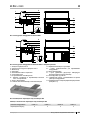
Rys.1 Budowa urządzenia „Kasia GRZ” 2
Rys.2 Budowa urządzenia „Kasia Z GRZ” z zasobnikiem 2
Rys.3 Rozmieszczenie poprzeczek pod pojemniki GN 2
Rys.4 Rozłożenie pojemników GN 3
Rys.5 Usuwanie podestu drewnianego 3
Rys.6 Zestaw kołowy, jezdny 3
Rys.7 Montaż elementów szklanych i profi li aluminiowych 4
Rys.8 Panel sterowania 4
Rys.9 Wanna bemara 5
Rys.10 Demontaż szyby frontowej 6
Rys.11 Wymiana świetlówki 6
Rys.12 Tabliczka znamionowa 7
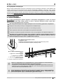
1. ROZŁADUNEK 1
2. CHARAKTERYSTYKA WYROBU 1
2.1. Przeznaczenie 1
2.2. Opis urządzenia 1
2.3. Dane techniczne 3
3. PRZYGOTOWANIE URZĄDZENIA DO EKSPLOATACJI 3
3.1. Wymagania dotyczące miejsca instalacji 3
3.2. Podłączenie i uruchomienie 3
4. EKSPLOATACJA 5
4.1. Poziom wody w wannie bemara 5
4.2. Regulacja temperatury 6
5. KONSERWACJA 6
5.1. Czyszczenie i konserwacja 6
6. SERWIS 7
6.1. Identyfi kacja i naprawa usterek 7
6.2. Serwis 7
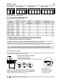
Ilości poprzeczek pod pojemniki GN 2
Dane techniczne 3
1. ROZŁADUNEK
Urządzenie powinno być transportowane w pozycji pionowej, odpowiednio zabezpieczone i spakowane. Producent wysy-
ła urządzenie na specjalnym podeście drewnianym, zabezpieczone tekturowymi kątownikami oraz folią.
2. CHARAKTERYSTYKA WYROBU
2.1. Przeznaczenie
Witryna „Kasia GRZ” przeznaczona jest do eksponowania i krótkoterminowego przechowywania wcześniej przygotowa-
nych gorących potraw w pojemnikach GN przed podaniem do konsumpcji. Witryny tego typu należą do podstawowego
wyposażenia w obiektach zbiorowego żywienia. Zakres regulacji temperatury wody w komorze wanny +30ºC/+90ºC.
2.2. Opis urządzenia
„KASIA GRZ” jest bemarem wodnym. Pojemniki GN umieszczane są nad kąpielą wodną ogrzewaną za pomocą grza-
łek elektrycznych zamocowanych bezpośrednio w wannie bemara. Witryna wyposażona jest w mechaniczny regulator
temperatury, regulator poziomu cieczy oraz nawiew ciepłego powietrza na szybę frontową. W zależności od typu i prze-
znaczenia „Kasie GRZ” wykonywane są w wersji z zasobnikiem (Z) lub bez zasobnika. W zależności od przeznaczenia
witryna wykonywana jest w wersji stacjonarnej lub jezdnej. Urządzenia „IGLOO” wykonywane są w/g nowoczesnych
technologii i posiadają wymagane prawem certyfi katy.
Tym znakiem oznaczone są informacje o szczególnym znaczeniu dla bezpieczeństwa użytkownika
oraz do prawidłowej eksploatacji urządzenia
Instrukcja obsługi
KASIA GRZ
pl

2
pl
Instrukcja obsługi Kasia GRZ www.igloo.pl
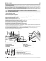
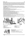
1 – Szyba frontowa uchylna
2 – Nadmuch ciepłego powietrza na szybę frontową
3 – Wentylator
4 – Podstawa
5 – Lampa aluminiowa z podświetleniem
6 – Półka szklana
7 - Pojemniki gastronomiczne GN
8 – Blat roboczy z blachy nierdzewnej - izolowany
9 – Korpus urządzenia
10 – Dolna część wanny bemara wypełniona wodą
11 – Zawór kulowy do spustu wody
12 - Nóżki służące do wypoziomowania urządzenia
13 – Tabliczka znamionowa urządzenia
14 – Panel sterowania (regulator temperatury / wyłączniki /
lampki kontrolne)
15 – Wiatrownica
16 – Podest drewniany zakładany do transportu urządzenia
17 - Drzwi zasobnika przesuwne lub uchylne (w witrynie 1.0)
Rys.2 Budowa urządzenia „Kasia Z GRZ” z zasobnikiem
Rys.3 Rozmieszczenie poprzeczek pod pojemniki GN
Rys.1 Budowa urządzenia „Kasia GRZ”
Tabela 1. Ilości poprzeczek pod pojemniki GN
Nazwa urządzenia Kasia 1.0 Kasia 1.3 Kasia 1.5 Kasia 1.7
Poprzeczki GN [szt] 2 3 3 4
13
14
15
9
10
11
12
8
5
6
7
16
1
2
3
4
NS-069 XXX
MASA xxx
NAPIECIE ZNAM. xxx
MOC ZN. OŒW. xxx
MOC GRZA£EK. xxx
NAPIECIE ZNAM. xxx
KLASA URZADZ. xxx
Typ NAZWA URZ¥DZENIA
PR¥D ZNAM. xxx
9
10
11
12
17
8
5
6
7
15
14
13
1
2
3
4

3
pl
Instrukcja obsługi Kasia GRZwww.igloo.pl
Rys.4 Rozłożenie pojemników GN
2.3. Dane techniczne
Tabela 2 Dane techniczne
Nazwa urządzenia
Napięcie
znam. [V/Hz]
Prąd
znamion. [A]
Moc znamion.
oświetlenia [W]
Zużycie energii
elektrycznej [kWh/1h]
Optymalna
pojemność wody [l]
Waga
[kg]
KASIA 1.0 GRZ 230/50 12,4 18 0,9 26 60
KASIA 1.0 Z GRZ 230/50 12,4 18 0,9 26 70
KASIA 1.3 GRZ 230/50 12,5 30 1,0 36 70
KASIA 1.3 Z GRZ 230/50 12,5 30 1,0 36 80
KASIA 1.5 GRZ 230/50 12,5 36 1,0 42 80
KASIA 1.5 Z GRZ 230/50 12,5 36 1,0 42 90
KASIA 1.7 GRZ 230/50 12,6 58 1,0 48 95
KASIA 1.7 Z GRZ 230/50 12,6 58 1,0 48 105
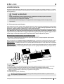
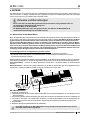
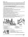
3. PRZYGOTOWANIE URZĄDZENIA DO EKSPLOATACJI
3.1. Wymagania dotyczące miejsca instalacji
• Sprawdź, czy przekrój przewodów zasilających jest odpowiedni dla poboru prądu instalowanego urządzenia
• Zabrania się podłączania urządzenia przez przewody przedłużające lub rozdzielacze
• Urządzenie należy podłączyć do oddzielnego, prawidłowo wykonanego obwodu elektrycznego z gniazdem
wtykowym z kołkiem ochronnym (w/g PBUE)
Uruchomienie urządzenia, może nastąpić tylko po potwierdzeniu skuteczności ochrony przeciwporaże-
niowej wynikami z pomiarów, przeprowadzonymi zgodnie z obowiązującymi przepisami!
3.2. Podłączenie i uruchomienie
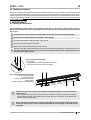
• Rozpakować urządzenie i usunąć drewniany podest znajdujący się na podstawie (nie dotyczy witryn z zasobnikiem
i witryn jezdnych) Rys.5 (str.3)
• Witrynę ustawić na równym i dostatecznie twardym podłożu, a na-
stępnie wypoziomować ją za pomocą nóżek. W przypadku bema-
rów jezdnych należy zastosować blokadę kół w celu uniemożliwienia
przesuwania się bemara podczas jego eksploatacji Rys.6 (str.3).
Rys.5 Usuwanie podestu drewnianego
Rys.6 Zestaw kołowy, jezdny
1. Wykręcić nóżki z podestu
2. Usunąć drewniany podest
3. Wkręcić nóżki w nakrętki przyspawane do ramy urządzenia
A – pozycja jezdna
B – pozycja blokady
B
A
123
1/4
Kasia 1.0 GRZ
Kasia 1.3 GRZ Kasia 1.5 GRZ
1/4
GN
1/1
1/4
1/4
GN
1/1
GN
1/1
GN
1/1
GN
1/1
GN
1/1
GN
1/1
GN
1/1
GN
1/1
Kasia 1.7 GRZ
GN
1/1
GN
1/1
GN
1/1
GN
1/1
1/4
1/4

4
pl
Instrukcja obsługi Kasia GRZ www.igloo.pl
1 – Szyba frontowa gięta, uchylna
2 – Lampa aluminiowa
3 – Zaślepka lampy aluminiowej
4 – Półka szklana
5 – Profi l aluminiowy górny (prowadnica uchylna) szyby
6 – Profi l aluminiowy (rurki) pod półkę szklaną
7 – Element mocujący półkę szklaną
8 – Bok szklany
9 – Osłona przewodu lampy
10 – Blat roboczy
11 – Prowadnica przysłonek nocnych
Rys.7 Montaż elementów szklanych i profi li aluminiowych
1 – Wyłącznik główny – włącz/wyłącz grzałki bemara
2 – Wyłącznik oświetlenia
3 - Pokrętło regulatora temperatury
4 – Kontrolka zielona - sygnalizuje niski poziom wody
5 - Kontrolka czerwona - sygnalizuje bardzo niski poziom wody
Rys.8 Panel sterowania
• Pierwsze mycie urządzenia powinno być wykonane po rozpakowaniu urządzenia i przed jego uruchomieniem. Urzą-
dzenie należy umyć wodą o temperaturze nieprzekraczającej 40ºC z dodatkiem neutralnych środków czyszczących.
Do mycia i czyszczenia urządzenia zabrania się stosowania środków zawierających chlor i sód różnych odmian,
które niszczą warstwę ochronną i elementy składowe urządzenia
!
Ewentualne pozostałości klejów czy silikonu na
elementach metalowych urządzenia usuwać wyłącznie benzyną ekstrakcyjną (nie dotyczy elementów z plastiku i tworzyw
sztucznych!). Nie wolno używać innych rozpuszczalników organicznych.
Podczas mycia urządzenia zabrania się używać strumienia wody. Urządzenie należy myć
przy użyciu wilgotnej ściereczki
• Jeżeli urządzenie trafi do użytkownika częściowo zdemontowane dla zabezpieczenia w czasie transportu należy
wykonać następujące operacje:
I. Zamontować boki szklane Rys.7/8 (str.4)
II. Zamontować lampę aluminiową (wraz z oświetleniem) na boczkach szklanych Rys.7/2 (str.4)
III. Zamontować szybę frontową, opierając ją na lampie i bokach szklanych Rys.7/1 (str.4)
IV. Zamontować profi le aluminiowe pod półkę szklaną (opcja) Rys.7/6 (str.4)
V. Zamontować półkę
szklaną Rys.7/4 (str.4)
VI. Założyć osłonę przewodu lampy Rys.7/9 (str.4)
Osłonę przewodu należy nasunąć na tył boku szklanego tak, aby przewód wychodzący z lampy był ukryty w osłonie
i znajdował się po wewnętrznej stronie boku szklanego!
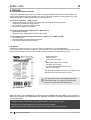
• Sprawdzić czy zawór kulowy spustu wody jest zamknięty Rys.1/11 (str.2)
• Wannę bemara zalać odpowiednią ilością czystej wody Rys.9 /2 (str.5)
• W wannie bemara umieścić osłony grzałek Rys.9/1 (str.5)
• Na wannie bemara rozłożyć poprzeczki pod pojemniki GN Rys.3 (str.2)
• Niezatowarowane pojemniki GN umieścić w komorze wg Rys.4 (str.3)
• Umieścić wtyczkę przewodu przyłączeniowego bezpośrednio w gnieździe wtykowym (zabrania się podłączania urzą-
dzenia przez przewody przedłużające lub rozdzielacze!)
• Załączyć przycisk wyłącznika głównego Rys.8/1 (str.4), co spowoduje załączenie grzałek elektrycznych wanny bemara
• Za pomocą pokrętła regulatora Rys.8/3 (str.4) ustawić żądaną temperaturę
• Po osiągnięciu żądanej temperatury wody, zatowarować pojemniki GN gorącymi produktami spożywczymi
• Załączyć przycisk wyłącznika oświetlenia Rys.8/2 (str.4)
12 354
812
10
34
8
9
7
11
5
6

5
pl
Instrukcja obsługi Kasia GRZwww.igloo.pl
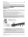
1 – Osłony grzałek
2 – Optymalny poziom cieczy dla prawidłowej pracy bemara (brak sygnalizacji świetlnej kontrolek na panelu sterowania)
3 – Sonda optymalnego poziomu cieczy (poniżej tego poziomu załącza się sygnalizacja kontrolki zielonej)
4 - Sonda poziomu alarmu – bardzo niski poziom cieczy w wannie (sygnalizacja kontrolki czerwonej), poniżej którego
włączany jest alarm dźwiękowy z jednoczesnym wyłączeniem funkcji grzania
5 – Czujnik temperatury
6 – Grzałki elektryczne (wodne 1400W/220V)
W trakcie prawidłowego wypełnienia wanny bemara wodą, kontrolki świetlne na panelu sterowa-
nia nie powinny się świecić wcale.
Rys.9 Wanna bemara
4. EKSPLOATACJA
Temperatura grzanej przestrzeni ekspozycyjnej może ulegać wahaniom. Zależy ona od wielu czynników m. in. od ilości
i temperatury włożonych produktów oraz od temperatury otoczenia. Urządzenie należy ustawić w miejscu suchym, do-
brze wentylowanym.
Uwagi i wskazówki
• Przed umieszczeniem w witrynie gorącego towaru, niezatowarowana witryna powinna pracować
do czasu osiągnięcia właściwej temperatury roboczej
• Nie wstawiać zimnych produktów do urządzenia
• Nie blokować otworów wentylacyjnych, co mogłoby utrudnić nawiew ciepłego powietrza na szybę frontową
Rys.1/2 (str.2)
4.1. Poziom wody w wannie bemara
Przed załączeniem bemara wodnego należy sprawdzić zamknięcie zaworu kulowego znajdującego się poniżej korpusu
witryny Rys.1/11 (str.2) i wypełnić wannę odpowiednią ilością czystej wody. Wodę wlewamy bezpośrednio do wanny
bemara (np. wężem gumowym) uważając, aby nie zalać części elektrycznej!
Aby bemar działał prawidłowo należy uzupełniać wodę w wannie tak, żeby sondy poziomu cieczy były stale zanu-
rzone. Należy zwrócić uwagę, aby poziom dolewanej wody nie był zbyt wysoki, ze względu na wydłużenie czasu jej
nagrzewania. Poza tym woda może nie osiągnąć odpowiedniej, wysokiej temperatury, a grzałki mogą pracować w
sposób ciągły, co spowoduje większy pobór energii elektrycznej i szybsze zużywanie się
grzałek.
Dla zapewnienia minimalnego zużycia energii elektrycznej należy:
• Dolewać wody o jak najwyższej temperaturze, celem skrócenia czasu rozruchu
• Podczas pracy urządzenia zakrywać wannę bemara pojemnikami GN celem zmniejszenia zjawiska odparowywania
wody i skrócenia procesu jej nagrzewania
Bemar wyposażony jest w regulator poziomu cieczy SPW-4 służący
do sterowania i nadzorowania poziomem wody w
wan
nie. Regulator ten jest wyposażony w dźwiękową i świetlną sygnalizację Rys.8/4;5 (str.4) obrazującą stan pracy bemara.
Kontrolka zielona – sygnalizuje niski poziom wody, funkcja grzania jest nadal aktywna - należy dolać wodę do zgaśnięcia
kontrolki.
Kontrolka czerwona – sygnalizuje bardzo niski poziom wody w wannie, funkcja grzania jest aktywna (do momentu włączenia
sygnalizacji dźwiękowej) – należy bezwzględnie dolać wodę do momentu zgaśnięcia kontrolki czerwonej, a następnie zielonej.
6
5
324
4

6
pl
Instrukcja obsługi Kasia GRZ www.igloo.pl
5. KONSERWACJA
5.1. Czyszczenie i konserwacja
Raz na tydzień zaleca się przerwę w eksploatacji urządzenia celem oczyszczenia jego wnętrza. Zabrudzoną wodę
należy usunąć z wanny otwierając zawór kulowy spustu wody znajdującego się pod korpusem Rys.1/11 (str.2).
Wszelkie czynności konserwacyjne należy prowadzić po odłączeniu urządzenia od napięcia!
Chronić przed uszkodzeniem lub zalaniem wodą instalację elektryczną
Do czyszczenia urządzenia nie należy używać strumienia wody, a jedynie wilgotnej ściereczki
Nie należy stosować żadnych ostrych przedmiotów celem usuwania zabrudzeń!
Urządzenia wyposażone w kółka jezdne nie mogą być eksploatowane na nierównych powierzchniach!
Podczas mycia wnętrza urządzenia nie wolno zostawiać szyby frontowej swobodnie uchylonej w pro-
fi lu aluminiowym. Grozi to uszkodzeniem szyby i nie podlega gwarancji. Szybę na czas konserwacji
wyciągnąć wraz z profi lem Rys.10 (str.6)
Rys.10 Demontaż szyby frontowej
1- Szyba frontowa
2- Profi l aluminiowy górny (prowadnica uchylna) szyby
3- Profi l aluminiowy dolny (zawias) szyby
4.2. Regulacja temperatury
Bemar wyposażony jest w mechaniczny regulator temperatury. Czujnik temperatury umieszczona jest w wannie bemara.
Za pomocą pokrętła regulatora Rys.8/3 (str.4) ustawiamy żądaną temperaturę wody w wannie poprzez dokonanie obrotu
pokrętłem i ustawienie go w odpowiednim położeniu. Obrót pokrętła w kierunku zgodnym z ruchem wskazówek zegara
powoduje podwyższenie nastawionej temperatury, a w kierunku przeciwnym jej obniżenie. Pokręcenie pokrętłem w lewo do
krańcowego położenia powoduje wyłączenie pracy grzałek, pomimo włączonego zasilania.
Rys.11 Wymiana świetlówki
1 – Uchwyt świetlówki
2 – Świetlówka
3 – Oprawa świetlówki i zapłonnika
4 – Zapłonnik świetlówki
Elementy urządzenia mogą korodować przy niewłaściwym użytkowaniu i konserwacji.
Należy przestrzegać zasad:
• Nie dopuszczać do kontaktu powierzchni urządzenia z środkami zawierającymi chlor i/lub sodę
w różnych odmianach, które niszczą ich warstwę ochronną i elementy składowe urządzenia
(dotyczy również różnych gatunków stali nierdzewnej)
Podczas czynności konserwujących należy uważać, aby nie uszkodzić tabliczki znamionowej urzą-
dzenia Rys.12 (str.7), która zawiera istotne informacje dla serwisantów oraz fi rm zajmujących się
usuwaniem odpadów.
34
21
123

7
pl
Instrukcja obsługi Kasia GRZwww.igloo.pl
6. SERWIS
6.1. Identyfi kacja i naprawa usterek
W przypadku wystąpienia jakichkolwiek trudności podczas uruchamiania urządzenia lub podczas jego eksploatacji należy
powrócić do tych rozdziałów instrukcji obsługi, które wyjaśniają wykonywaną operacje. Ma to na celu upewnienie się, czy
urządzenie jest prawidłowo obsługiwane. Jeżeli trudności występują nadal, poniższe wskazówki pomogą w ich usunięciu.
Urządzenie nie pracuje...- Upewnić się, czy:
• Napięcie i częstotliwość w sieci są odpowiednie z tymi, jakie zaleca producent (patrz tabliczka znamionowa) (patrz
tabliczka znamionowa)
• Urządzenie jest podłączone do sieci prądu elektrycznego
• Włączony jest wyłącznik główny znajdujący się na panelu sterującym
• Pokrętło regulatora temperatury nie jest w pozycji wyłączonej
Oświetlenie nie świeci...- Upewnić się, czy:
• Wyłącznik o
świetlenia jest w pozycji załączonej
• Świetlówka w lampie nie uległa spaleniu
Urządzenie nie osiąga odpowiedniej temperatury, oświetlenie świeci...- Upewnić się, czy:
• Wyłącznik główny jest załączony
• Nastawa temperatury na pokrętle regulatora jest odpowiednio nastawiona
• Jest woda w wannie i jaki jest jej poziom
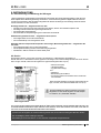
6.2. Serwis
Tel. do serwisu IGLOO: +48 (14) 662 19 56 lub +48 605 606 071 e-mail: [email protected]
Jeśli po sprawdzeniu punktów opisanych w rozdziale 6.1 „Identyfi kacja i naprawa usterek” urządzenie nadal nie działa
prawidłowo, należy skontaktować się z Serwisem Technicznym fi rmy Igloo, podając dane z tabliczki znamionowej Rys.12
(str.7)
• Numer seryjny (NS)
• Datę produkcji
• Typ (nazwa urządzenia)
oraz
• Datę zakupu urządzenia
• Opis problemu
• Dokładny adres i numer telefonu wraz
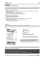
z numerem kierunkowym do Państwa
Tabliczka znamionowa znajduje się z tyłu urządzenia,
w prawym, górnym rogu poniżej blatu Rys.1/13 (str.2).
Powyższy rysunek przedstawia poglądową tabliczkę
znamionową, a dane w niej zawarte są danymi przykła-
dowymi nieodnoszącymi się do „Kasi GRZ”!
Rys.12 Tabliczka znamionowa
UWAGA: W PRZYPADKU NIE ZASTOSOWANIA SIĘ DO ZASAD ZAWARTYCH W NINIEJSZEJ INSTRUKCJI DO-
TYCZĄCYCH PODŁĄCZENIA I EKSPLOATACJI URZĄDZENIA, PRODUCENT ZASTRZEGA SOBIE PRAWO OD-
STĄPIENIA OD OBOWIĄZKÓW GWARANTA!!!
Informacje zawarte w tym dokumencie mogą być zmienione przez „IGLOO” bez powiadamiania użytkownika.
Kopiowanie niniejszej instrukcji bez zgody producenta jest zabronione.
Zdjęcia oraz rysunki mają charakter poglądowy i mogą się różnić od zakupionego urządzenia.

en
8
User manual Kasia GRZ www.igloo.pl
Fig.1 Construction of „Kasia GRZ” device 9
Fig.2 Construction of „Kasia Z GRZ” device with reservoir 9
Fig.3 Layout of cross-bars under GN containers 9
Fig.4 Layout of GN containers 10
Fig.5 Removing the wooden platform 10
Fig.6 Wheel system, moving system 10
Fig.7 Assembly of glass elements and aluminium profi les 11
Fig.8 Control panel 11
Fig.9 Bain-marie tank 12
Fig.10 Front glass disassembly 13
Fig.11 Changing the fl uorescent lamp 13
Fig.12 Data plate 14
1. UNLOADING
The device should be transported in vertical position, and it should be properly secured and packed. The manufacturer
ships the device on a special wooden platform, secured with cardboard angle sections and foil.
2. PROPERTIES OF THE DEVICE
2.1. Purpose
“Kasia GRZ” display cabinet is used to display and short-lasting storage of previously prepared hot dishes in GN con-
tainers before serving them. These devices constitute basic elements of equipment in mass feeding facilities. Scope of
water temperature regulation in tank chamber ranges between +30ºC/+90ºC.
2.2. Description of the device
KASIA GRZ” is a water bain-marie. GN containers are placed over the water bath heated with electrical heaters placed
directly in bain-marie tank. The display cabinet is equipped with mechanical temperature regulator, fl uid level regulator and
front glass hot air inlet. Depending on the type and purpose of the display cabinet, “Kasia GRZ” devices are available in
two versions, with (Z) or without the reservoir. Depending on its purpose, the display cabinet is manufactured in stationary
and moving version. Our devices are made according to modern technologies and have all certifi cates required by law.
This sign signifi es information of particular meaning for user security and for proper device
exploitation.
Contents List of Figures
List of tables
Table 1. Number of cross-bars under GN containers 9
Table 2. Technical data 10
User manual KASIA GRZ
1. UNLOADING 8
2. PROPERTIES OF THE DEVICE 8
2.1. Purpose 8
2.2. Description of the device 8
2.3. Technical data 10
3. PREPARING THE DEVICE FOR EXPLOITATION 10
3.1. Requirements concerning the place of installation 10
3.2. Connection and actuation 10
4. EXPLOITATION 12
4.1. Water level in bain-marie tank 12
4.2. Temperature regulation 13
5. MAINTENANCE 13
5.1. Cleaning and maintenance 13
6. SERVICE 14
6.1. Fault identifi cation and repair 14
6.2. Service 14
en

en
9
User manual Kasia GRZwww.igloo.pl
1 – Front lifted glass
2 – Front glass hot air inlet
3 – Ventilator
4 – Basis
5 – Aluminium lamp with illumination
6 – Glass shelf
7 – GN gastronomic containers
8 – Working top made of stainless steel - insulated
9 – Body of the device
10 – Lower part of bain-marie tank fi lled with water
11 – Water outlet ball valve
12 – Device levelling feet
13 – Data plate of the device
14 – Control panel (temperature regulator / switch / control
lamps)
15 – Wind brace
16 – Wooden platform fi xed for transporting the device
17 – Lifted or sliding reservoir doors (in 1.0 display cabinet)
Fig.2 Construction of the „Kasia GRZ” device with reservoir
Fig.3 Layout of cross-bars under GN containers
Fig.1 Construction of the „Kasia GRZ” device
Table 1 Number of cross-bars under GN containers
Name of the device Kasia 1.0 Kasia 1.3 Kasia 1.5 Kasia 1.7
GN cross-bars [items] 2 3 3 4
13
14
15
9
10
11
12
8
5
6
7
16
1
2
3
4
NS-069 XXX
MASA xxx
NAPIECIE ZNAM. xxx
MOC ZN. OŒW. xxx
MOC GRZA£EK. xxx
NAPIECIE ZNAM. xxx
KLASA URZADZ. xxx
Typ NAZWA URZ¥DZENIA
PR¥D ZNAM. xxx
9
10
11
12
17
8
5
6
7
15
14
13
1
2
3
4

en
10
User manual Kasia GRZ www.igloo.pl
Fig.4 Layout of GN containers
2.3. Technical data
Table 2. Technical data
Name of the device
Rated volta-
ge [V/Hz]
Rated
current [A]
Rated lighting
power [W]
Electric energy con-
sumption [kWh/1h]
Optimal water
volume [l]
Weight
[kg]
KASIA 1.0 GRZ 230/50 12,4 18 0,9 26 60
KASIA 1.0 Z GRZ 230/50 12,4 18 0,9 26 70
KASIA 1.3 GRZ 230/50 12,5 30 1,0 36 70
KASIA 1.3 Z GRZ 230/50 12,5 30 1,0 36 80
KASIA 1.5 GRZ 230/50 12,5 36 1,0 42 80
KASIA 1.5 Z GRZ 230/50 12,5 36 1,0 42 90
KASIA 1.7 GRZ 230/50 12,6 58 1,0 48 95
KASIA 1.7 Z GRZ 230/50 12,6 58 1,0 48 105
3. PREPARING THE DEVICE FOR EXPLOITATION
3.1. Requirements concerning the place of installation
• Verify whether the cross section of feeding conduits is proper for power consumption of the installed device.
• It is forbidden to connect the device by extension rods or dividers.
• The device should be connected to the separate, properly made electric circuit with plug-in socket with protecting
pin (according to PBUE /Regulations concerning Electric Equipment Construction/)
The device may be actuated solely after confi rmation of the fi re protection effi ciency with results of measu-
res performed according to binding regulations!
3.2. Connection and actuation
• Unpack the device and remove the wooden platform from the basis (does not concern moving devices as well
as display cabinets with reservoir) Fig.5 (p.10)
• Place the display cabinet on an even basis, which is hard enough,
and then level it with feet. In case of moving bain-marie devices it is
necessary to block the wheels in order to immobilise the bain-marie
device during its exploitation. Fig.6 (p.10).
Fig.5 Removing the wooden platform
Fig.6 Wheel system, moving system
1 – Unscrew the feet from the platform
2 – Remove the wooden platform
3 – Screw the feet in nuts welded to the frame of the device
A – moving position
B – blockade position
B
A
GN
1/1
Kasia GRZ 1.0 Kasia GRZ 1.3 Kasia GRZ 1.5
1/4
1/4
GN
1/1
1/4
1/4
GN
1/1
GN
1/1
GN
1/1
GN
1/1
GN
1/1
GN
1/1
GN
1/1
GN
1/1
GN
1/1
GN
1/1
GN
1/1
1/4
1/4
Kasia GRZ 1.7

en
11
User manual Kasia GRZwww.igloo.pl
1 – Bent front glass, lifted
2 – Aluminium lamp
3 – Aluminium lamp hole plug
4 – Glass shelf
5 – Upper aluminium profi le (lifted guide) of the glass
6 – Aluminium profi le (pipes) under the glass shelf
7 – Glass shelf fi xing element
8 – Glass side
9 – Lamp conduit protection
10 – Working top
11 – Night screen guide
Fig.7 Assembly of glass elements and aluminium profi les
1 – Main switch – turn on/off bain-marie heaters
2 – Light switch
3 – Temperature regulator knob
4 – Green diode – signals low water level
5 – Red diode – signals very low water level
Fig.8 Control panel
• If the user shall obtain a device partially disassembled to secure it during transportation, perform the following operations:
I. Mount glass sides Fig.7/8 (p.11)
II. Mount the aluminium lamp (together with lighting) on glass sides Fig.7/2 (p.11)
III. Mount the front glass, basing it on the lamp and glass sides Fig.7/1 (p.11)
IV. Mount aluminium profi les under the glass shelf (optional) Fig.7/6 (p.11)
V. Mount the glass shelf Fig.7/4 (p.11)
VI. Mount the casing of lamp conduit Fig.7/9 (p.11)
Move the casing of lamp conduit to the back of the glass side, in order to hide the conduit coming out of the lamp in the
casing and to place it on the internal part of the glass side!
• Check whether the water outfl ow ball valve is closed Fig.1/11 (p.9)
• Fill bain-marie tank with proper amount of clean water Fig.9 /2 (p.12)
• Place heater screens in bain-marie tank Fig.9/1 (p.12)
• Place cross-bars under GN containers on the bain-marie tank Fig.3 (p.9)
• Place empty GN containers in the chamber according to Fig.4 (p.10)
• Place the plug of the connecting cable directly in plug-in socket (it is forbidden to connect the device by means
of extension cords or dividers!)
• Turn on the main switch Fig.8/1 (p.11), which activates the electric heaters of bain-marie tank
• Set the desired temperature on thermostat control panel Fig.8/3 (p.11)
• After obtaining the desired water temperature, put hot grocery products in GN containers
• Turn on the lighting switch Fig.8/2 (p.11)
• The fi rst cleaning of the device should be provide right after unpacking, and before turning it on. The unit should
be cleaned with water at a temperature not exceeding 40°C with a neutral detergent. For washing and cleaning
the equipment it is prohibited to use products containing chlorine and sodium varieties, which destroy the protecti-
ve layer and components of the device! Any residue of adhesives or silicone on metal elements should be remo-
ved only with extraction naphtha (not applicable to items made of plastic !). Do not use other organic solvents.
When cleaning the unit is prohibited to use water jet. The unit should be cleaned with a wet rag.
12 354
812
10
34
8
9
7
11
5
6

en
12
User manual Kasia GRZ www.igloo.pl
1 – Heater screens
2 – Optimum fl uid level required for proper bain-marie operation (diodes on the control panel are off)
3 – Optimum fl uid level sensor (green diode shall illuminate when fl uid falls below this level)
4 – Alarm level sensor – very low level of fl uid in the tank (red diode signal), when fl uid level falls below this sensor sound alarm
is activated and heating function is simultaneously inactivated
5 – Temperature sensor
6 – Electric heaters (water heaters - 1400W/220V)
When bain-marie tank is properly fi lled with water, control panel diodes should not be illumina-
ted at all.
Fig.9 Bain-marie tank
4. EXPLOITATION
Temperature of the heated display space may vary. It depends on numerous factors, such as amount and temperature
of products placed in the device and temperature of the surroundings. The device should be placed in a dry and well-
ventilated place.
Remarks and indications
• Before placing hot products in the display cabinet, an empty display cabinet should operate until
the desired working temperature shall be obtained.
• Do not place cold products in the device
• Do not block ventilation holes, as this could hinder the front glass hot air inlet Fig.1/2 (p.9)
4.1. Water level in bain-marie tank
Before connecting water bain-marie it is essential to check the closure of ball valve located below the display cabinet body
Fig.1/11 (p.9) and fi ll the tank with proper amount of clean water. We pour the water directly into the bain-marie tank (f.
ex. With rubber hose) to avoid fl ooding the electric part!
To ensure proper operation of the bain-marie, it is essential to complete the water in the tank, to ensure constant im-
mersion of water level sensors. The level of poured cannot be too high, as this can prolong the water heating time.
Apart from the above, the water may not reach the proper, high temperature, and heaters may work continuously,
which will cause greater power consumption and quicker wear and tear of the heaters.
To ensure minimal electric energy consumption, it is essential to:
• Add water of highest possible temperature in order to shorten the actuation time
• When the device is operating, please cover the bain-marie tank with GN containers in order to decrease water evaporation
and shorten the water heating time
Bain-marie is equipped with SPW-4 water level regulator used to control and manage tank water level. This regulator is
equipped with sound and light signalling Fig.8/4; 5 (p.11) illustrating bain-marie operating condition.
Green diode – signals low water level, the heating function is still active – pour the water into the tank, until the diode will
be off.
Red diode – signals very low water level in the tank, the heating function is still active (until sound signalling will be activated)
– it is absolutely necessary to pour the water until the red diode, and then the green diode will be off.
6
5
324
4

en
13
User manual Kasia GRZwww.igloo.pl
5. MAINTENANCE
5.1. Cleaning and maintenance
It is recommended to make a break in the exploitation of the device once a week in order to clean its interior.
Remove the dirty water from the tank by opening the water outfl ow ball valve placed below the body of the device
Fig.1/11 (p.9).
All maintenance services need to be performed after disconnecting the device from power supply!
Protect electric installation against any damage or water spillage
Do not use water stream to clean the device, only a wet cloth
Do not use any sharp objects to remove dirt!
Devices with wheels cannot be used on uneven surfaces!
During cleaning the inside of the device do not leave the front glass freely lifted in the aluminium profi le. This
may cause the damage of the glass and is not covered by warranty. Please remove the glass with profi le for
the time of cleaning Fig.10 (p.13)
Fig.10 Front glass disassembly
1- Front glass
2- Upper aluminium profi le (lifted guide) of the glass
3- Lower aluminium profi le (catch) of the glass
4.2. Temperature regulation
Bain-marie is equipped with mechanical temperature regulator. Temperature sensor is located in the bain-marie tank. We
set the desired water temperature in the tank Fig.8/3 (p.11) with the help of regulating knob by turning it and setting in proper
position. Turning the knob clockwise increases the set temperature, and turning it in the opposite direction causes the de-
crease of temperature. Turning the knob left, until it reaches the fi nal position turns off the heaters, despite the fact that the
power supply is activated.
Fig.11 Changing the fl uorescent lamp
1 – Fluorescent lamp handle
2 – Fluorescent lamp
3 – Casing of fl uorescent lamp and
starting switch
4 – Starting switch of fl uorescent lamp
During maintenance services it is necessary to pay attention not to damage the data place of the
device Fig.12 (p.14), which contains signifi cant information for servicing organs and waste removal
companies.
Elements of device can corrode when improper used and maintenance. To avoid that please
follow the rules:
• Do not allow contact of the surface of the device with substances containing chlorine and / or baking
soda in different varieties, which destroy the protective layer and components of the device (also
includes various stainless steel)
34
21
123

en
14
User manual Kasia GRZ www.igloo.pl
6. SERVICE
6.1. Fault identifi cation and repair
In case of any diffi culties during actuation of the device or during its exploitation, please return to these chapters in this
manual, which explain the performed operation. This aims to ensure that the device is properly operated. If you still
experience diffi culties, the following hints will help you solve the problem.
The device is not working... – Make sure that:
• Voltage and frequency in the network are compliant with those recommended by the producer
• The device is connected to the supply network
• The main switch on the control panel is turned on
• Temperature regulating knob is turned on
The device is operating, but the lighting is off...– Make sure that:
• Lighting switch is turned on
• Fluorescent lamp or starting switch of the device are not burnt
The device does not reach the proper temperature, the lighting is on...– Make sure that:
• The main switch is on
• Temperature setting on the thermostat is properly set
• There is water in the tank and check its level
6.2. Service
IGLOO service telephone number: +48 (14) 662 19 56 or +48 605 606 071, e-mail: [email protected]
If after checking points described in chapter 6.1 “Fault identifi cation and repair” the device still does not work properly,
please contact Technical Service of the Igloo company, stating the data from the data plate Fig.12 (p.14)
• Serial number (NS)
• Production date
• Type (name of the device)
and
• Date when the device was purchased
• Description of the problem
• Your exact address and telephone number
(with the code number)
The data plate is located at the back of the device, at the
upper right corner, below the top Fig.1/13 (p.9).
The above fi gure shows a demonstrative data plate
and the data stated on the plate are exemplary data,
which are not related with “Kasia GRZ” device!
NOTE: IN CASE OF NOT OBSERVING THE PRINCIPLES ON CONNECTING AND USING THE DEVICE INCLU-
DED IN THIS MANUAL, THE PRODUCER SHALL RESERVE THE RIGHT TO RECEDE FROM OBLIGATIONS OF
THE GUARANTOR!!!
Information included in this document may be altered by “IGLOO” without noticing the user.
Copying the present manual without the consent of the producer is forbidden.
Images and drawings are of demonstrative character and may differ from the purchased device.
Fig.12 Data plate

de
15
Bedienungsanleitung Kasia GRZwww.igloo.pl
Abb.1 Bau der Anlage „Kasia GRZ” 16
Abb.2 Bau der Anlage „Kasia Z GRZ” mit dem Behälter 16
Abb.3 Anordnung der Querholme für GN-Behälter 16
Abb.4 Anordnung der GN-Behälter 17
Abb.5 Entfernen der Holzbühne 17
Abb.6 Fahrbarer Radsatz 17
Abb.7 Einbau der Glasteilen und Alulampe 18
Abb.8 Steuerungspaneel 18
Abb.9 Bain-Marie-Wanne 19
Abb.10 Frontscheibe 20
Abb.11 Austausch der Leuchtstoffl ampe in Lampe 20
Abb.12 Typenschild 21
Mit diesem Zeichen sind die wichtigen Sicherheitshinweisen für Benutzer und ordnungsgemäßen Be-
trieb der Anlage ausgezeichnet
BEDIENUNGSANLEITUNG
1. AUSLADUNG
Zur Beförderung soll diese Anlage in vertikaler Richtung eingestellt, angemessen gesichert und verpackt werden. Sie ist
durch den Hersteller auf einer speziellen Holzpalette, versichert durch Pappenwinkel und Folie gesendet.
2. PRODUKTBESCHREIBUNG
2.1. BESTIMMUNG
Die Vitrine „Kasia GRZ” dient zur Ausstellung und kurzfristigen Aufbewahrung von frührer bereiteten heißen Speisen in den
GN-Behälter, bevor diese zum gegessen serviert werden. Diese Anlagen können zum Ausrüsten der Bewirtungsbetrieben.
Bereich der Regelung von Wassertemperatur im Innenraum der Wanne +30ºC/+90ºC.
2.2. Beschreibung der Anlage
„KASIA GRZ” jest bemarem wodnym. ist ein Wasser-Bain-Marie. Die GN-Behälter sind über das Wasserbad unterbracht,
die mit den elektrischen Heizelementen erwärmt ist. Witryna wyposażona jest w mechaniczny regulator temperatury, re-
gulator poziomu cieczy oraz nawiew ciepłego powietrza na szybę frontową. W zależności od typu i przeznaczenia „Kasie
GRZ” wykonywane są w wersji z zasobnikiem (Z) lub bez zasobnika.
Abhängig von dem Bau und Bestimmung ist diese Vitrine als fahrbar oder stationär zugänglich. Unsere Anlagen sind nach
dem aktuellen Stand der Technik ausgeführt und rechtsgemäß geprüft.
Inhaltsverzeichnis Verzeichnis der Abbildungen
Verzeichnis der Tabellen
Tabelle 1. Menge der Querholme für GN-Behälter 16
Tabelle 2. Technische Angaben 17
KASIA GRZ
de
1. AUSLADUNG 15
2. PRODUKTBESCHREIBUNG 15
2.1. Bestimmung 15
2.2. Beschreibung der Anlage 15
2.3. Technische Angaben 17
3. BEREITSTELLUNG DER ANLAGE ZUM BETRIEB 17
3.1. Anforderung an Einstellungsort 17
3.2. Anschluss und Inbetriebnahme 17
4. BETRIEB 19
4.1. Wasserstand in Bain-Marie-Wanne 19
4.2. Die Temperaturregelung 20
5. WARTUNG 20
5.1. Reinigung und Wartung 20
6. INSTANDHALTUNG 21
6.1. Kennzeichnung und Behebung der Störungen 21
6.2. Service 21

de
16
Bedienungsanleitung Kasia GRZ www.igloo.pl
1 – Kipp-Vorderscheibe
2 – Wärmeluftzufuhr für die Vorderscheibe
3 – Belüfter
4 – Grundlage
5 – Alulampe mit Beleuchtung
6 – Glasregal
7 – Gastronomische GN-Behälter
8 – Arbeitsblatt aus nichrostendem Blech - isoliert
9 – Anlagekörper
10 – Unterteil der Bain-Marie-Wanne, mit Wasser befüllt
11 – Kugelventil für Wasserabfl uss
12 – Beinen zum Justieren der Anlage
13 – Typenschild
14 – Steuerungspaneel (Temepraturregelung / Schalter / Kon-
trolllampen)
15 – Windkasten
16 – Holzbühne, zum Einbauen bei Beförderung der Anlage
17 – Schibe- oder Kipptüren für den Behälter (in Vitrine 1.0)
Abb.2 Bau der Anlage „Kasia Z GRZ” mit dem Behälter
Abb.3 Anordnung der Querholme für GN-Behälter
Abb.1 Bau der Anlage „Kasia GRZ”
Tabelle 1. Menge der Querholme für die GN-Behälter
Name der Anlage Kasia 1.0 Kasia 1.3 Kasia 1.5 Kasia 1.7
Querholme GN [Stck] 2 3 3 4
13
14
15
9
10
11
12
8
5
6
7
16
1
2
3
4
NS-069 XXX
MASA xxx
NAPIECIE ZNAM. xxx
MOC ZN. OŒW. xxx
MOC GRZA£EK. xxx
NAPIECIE ZNAM. xxx
KLASA URZADZ. xxx
Typ NAZWA URZ¥DZENIA
PR¥D ZNAM. xxx
9
10
11
12
17
8
5
6
7
15
14
13
1
2
3
4

de
17
Bedienungsanleitung Kasia GRZwww.igloo.pl
Abb.4 Anordnung der GN-Behälter
2.3. Technische Angaben
Tabelle 2 Technische Angaben
Anlagetype
Nennspan-
nung. [V/Hz]
Nennstrom.
[A]
Nennleistung der
Beleuchtung [W]
Energieverbrauch
[kWh/1h]
Optimale Wasser-
kapazität [l]
Gewicht
[kg]
KASIA 1.0 GRZ 230/50 12,4 18 0,9 26 60
KASIA 1.0 Z GRZ 230/50 12,4 18 0,9 26 70
KASIA 1.3 GRZ 230/50 12,5 30 1,0 36 70
KASIA 1.3 Z GRZ 230/50 12,5 30 1,0 36 80
KASIA 1.5 GRZ 230/50 12,5 36 1,0 42 80
KASIA 1.5 Z GRZ 230/50 12,5 36 1,0 42 90
KASIA 1.7 GRZ 230/50 12,6 58 1,0 48 95
KASIA 1.7 Z GRZ 230/50 12,6 58 1,0 48 105
3. BEREITSTELLUNG DER ANLAGE ZUM BETRIEB
3.1. Anforderung an Einstellungsort
• Sie müssen prüfen, ob. der Durchschnitt der Versorgungsleitungen für dem Stromverbrauch der einzubauenden
Anlage geeignet ist
• Der Anschluss der Anlage mit den Verlängungsleitungen oder Verteilern ist stark verboten.
• Sie sollen die Anlage an separatem, richtig durchgeführtem Stromkreis mit Steckdose mit Schutzbolzen (nach PBUE)
Die Anlage kann in Betrieb erst genommen werden, wenn die Wirksamkeit des Brandschutzes durch die
Ergebnisse aus Messungen bestätigt wird, die gemäss den geltenden Vorschriften erfolgen!
3.2. Anschluss und Inbetriebnahme
• Die Anlage auspacken und das Holzpodest, dass auf der Grundlage vorhanden ist, entfernen
• Die Anlage auf einer ebener und ausführlich fester Grundlage stellen,
dann mit den Beinen justieren.
• Bei fahrbaren Anlagen die Räder sperren, um der Verschiebung bei
dem Betrieb vorzubeugen Abb.6 (S.17).
Abb.5 Entfernen der Holzbühne
Abb.6 Fahrbarer Radsatz
1 – Beinen ausschrauben
2 – Bühne entfernen
3 – Die Beinen in die Mutter einschrauben, die an dem Anlagerah-
men angeschweißt sind
A – Fahreinstellung
B – Sperrung
B
A
1/4
Kasia 1.0 GRZ
Kasia 1.3 GRZ Kasia 1.5 GRZ
1/4
GN
1/1
1/4
1/4
GN
1/1
GN
1/1
GN
1/1
GN
1/1
GN
1/1
GN
1/1
GN
1/1
GN
1/1
Kasia 1.7 GRZ
GN
1/1
GN
1/1
GN
1/1
GN
1/1
1/4
1/4

de
18
Bedienungsanleitung Kasia GRZ www.igloo.pl
1 – Gebogene Kippscheibe
2 – Alulampe
3 – Blende der Alulampe
4 – Glasregal
5 – Oberes Aluprofi l (Kippführung) der Scheibe
6 – Aluprofi l (Rohren) für Glasregal
7 – Befestigungselement für Glasregal
8 – Glasseite
9 – Mantel für Lampenleitung
10 – Arbeitsblatt
11 – Führung für Nachtblenden
Abb.7 Einbau der Glasteilen und Alulampe
1 – Hauptschalter – Heizelemente des Bain-Maries ein-/ ausschalten
2 – Beleuchtungschalter
3 – Drehschalter für die Temepraturregelung
4 – Grüne Kontrolllampe – signalisiert die niedrige Wasserhöhe
5 – Rote Kontrollampe – weist auf die sehr niedrige Wasserhöhe auf
Abb.8 Steuerungspaneel
• Soll der Benutzer die Anlage in einem teilweise ausgebautem Zustand bekommen, so ist diese mit folgenden Mitteln
zur Beförderung zu sichern:
I. Glasseiten anbringen Abb.7/8 (S.18)
II. Alulampe (mit Beleuchtung) an den Glasseiten einbauen Abb.7/2 (S.18)
III. Vorderscheibe einbauen, indem diese auf der Lampe und Glasseiten gestützt wird Abb.7/1 (S.18)
IV. Die Aluprofi le für den Glasregal einbauen (Option) Abb.7/6 (S.18)
V. Glasregal einbauen Abb.7/4 (S.18)
VI. Den Mantel für die Lampeleitung anbringen Abb.7/9 (S.18)
Der Leitungsmantel so an der Hinterseite der Glasseite anbringen, dass die Leitung, die aus der Lampe ausgeht, in
dem Mantel versteckt wird und von der innerer Seite der Glasseite vorhanden wird!
• Prüfen ob. der Kugelventil für Wasserablauf geschlossen ist Abb.1/11 (S.16)
• Die Bain-Marie-Wanne mit entsprechender Menge des Wassers befüllenAbb.9/2 (S.19)
• Die Heizelementschütze in der Bain-Marie-Wanne anbringen Abb.9/1 (S.19)
• Die Querholme für die Behälter in der Bain-Marie-Wanne anordnen Abb.3 (S.16)
• Die GN-Behälter, die mit den Speisen nicht beschafft sind, in dem Innraum unterbringen nach Abb.4 (S.17)
• Den Stecker der Anschlussleitung direkt in Steckdose stecken (es ist unzulässig, die Anlage mit den Verlängerung-
sleitungen oder Verteilern anzuschließen)
• Haup
tschalter-Taste drücken Abb.8/1 (S.18), die elektrischen Heizelemente der Bain-Marie-Wanne werden eingeschaltet.
• Auf der Temperaturregelung Abb.8/3 (S.18) die Temperatur einstellen
• Nachdem die gewünschte Wassertemperatur erreicht worden ist, sollen die GN-Behälter mit den heißen Speisen
beschafft werden Beleuchtungs-Taste drücken Abb.8/2 (S.18)
• Das erste Waschen der Anlage ist schon nach ihrem Auspacken und vor der Inbetriebnahme durchzuführen. Die
Anlage soll mit dem Wasser mit Zugabe an neutralen Reinigungsmittel gewaschen werden. Verwenden beim Put-
zen der Ätzmittel, die Chlor und/oder Soda verschiedener Art enthalten, ist verboten. Die Ätzmittel beschädigen
Schutzschicht und Bauteile der Anlage. Eventuelle Klebe- oder Silikonreste an den Metallteilen der Anlage sollen
nur mit dem Extraktionsbenzin entfernt werden (ausgeschlossen von Plastik- und Kunststoffelementen!). Keine
sonstige organische Auslösungsmittel verwenden.
Verwenden beim Putzen des Wasserstrahls ist verboten. Die Anlage nur mit feuchtem Tuch
reinigen.
12 354
812
10
34
8
9
7
11
5
6

de
19
Bedienungsanleitung Kasia GRZwww.igloo.pl
1 – Schütze für die Heizelemente
2 – Optimalerwasserstand für den richtigen Betrieb des Bain-Maries (keine optische Signalisation der Kontrollampen auf dem
Steuerungspaneel)
3 – Die Sonde für optimalen Stand der Flüssigkeit (unter dieser Höhe schaltet sich die Signalisation der grünen Kontrolllampe ein)
4 – Die Sonde für Alarmstand – sehr niedrige Höhe des Wasser in der Wanne (Signmaisation durch rote Kontrolllampe), sein
Unterschreiten verursacht, dass die Tonsignalisation mit gelichzeitigem Ausschaltung der Heizfunktion ausgelöst wird.
5 – Temperaturfühler
6 – Elektrische Heizelemente (Wasserheizelemente 1400W/220V)
Ist der Wasserstand in der Bain-Marie-Wanne richtig, erfolgt keine Signalisation durch die Kon-
trollampen auf dem Steuerungspaneel.
Abb.9 Bain-Marie-Wanne
4. BETRIEB
Die Temperatur des zu erwärmenden Raumes und Arbeitszyklus kann die Abweichungen aufweisen. Diese hängen von
mehrerer Faktoren u.a. Menge und Temperatur der eingelegten Produkten und Umgebungstemperatur ab. Die Anlage
soll auf einem trockenem, gut belüftetem Platz eingestellt werden.
Hinweise und Bemerkungen
• Bevor in der Vitrine die heiße Ware gestellt wird, hat die leere Vitrine so lange arbeiten sollen, bis
die angemessene Betriebstemperatur erlangt wird
• Keine kalte Waren in die Vitrine stellen
• Die Belüftungsöffnungen sollen nicht gesperrt werden, weil dadrurch der Warmluftzufuhr für
Vorderscheibe beeinträchtigt sein könnte Abb.1/2 (S.16)
4.1. Wasserstand in Bain-Marie-Wanne
Bevor das Wasser-Bain-Marie eingeschaltet wird, ist die Schließung des Kugelventils, das sich unter Vitrinengehäuse befi ndet 1/11
(S.16) zu prüfen und die Wanne mit entsprechender Menge des reinen Wassers zu befüllen. Das Wasser soll direkt in die Wanne
gegossen werden z.B. mit Gummischlauch, wobei es zu beachten ist, dass der elektrische Teil nicht übergossen wird.!
Um den richtigen Bain-Marie-Betrieb zu sichern, ist die Wanne mit dem Wasser so zu befüllen, dass die Wasser-
standröhre immer im Wasser getaucht wurden. Es ist zu beachten, dass die Höhe des zu gegossenden Wasser
nicht zu hoch wird, weil damit das Ermärmen des Wassers länger dauern wird. Ausserdem kann das Wasser die
entsprechend hohe Temepratur nicht erlangen, und die Heizelemente sich im Dauerbetrieb befi nden. Das verur-
sacht den grösseren Energieverbrauch und schnelleren Heizlementgebrauch.
Um den Energieverbrauch auf möglichst geringer Höhe zu halten:
• Beim Befüllen, das Wasser mit möglichst hoher Temperatur verwenden, um Anlaufzeit zu verkürzen
• Beim Betrieb die Bein-Marie-Wanne mit GN-Behälter decken, um das Abdampfen des Wassers zu verringern
und die Erwärmungszeit zu verkürzen
Das Bain-Marie ist mit Wasserstandregelung SPW-4 ausgestattet, die den Wasserstand in der Wanne regelt und überwacht.
Dieser Regelung besitzt die Ton- und optische Signalisation Abb.8/4;5 (S.22) mit der den Bain-Marie-Betrieb hingewiesen ist.
Grüne Kontrolllampe – weist auf die nidriege Wasserhöhe, Heizung aktiv – mit Wasser befüllen, bis die Kontrollampe
löscht hin.
Rote Kontrolllampe – weist auf sehr niedrige Wasserhöhe in der Wanne, Heizung aktiv (bis die Tonsignalisation einge-
schaltet wird) – unbedingt mit Wasser befüllen, bis die rote, und dann grüne Lampe löscht.
6
5
324
4

de
20
Bedienungsanleitung Kasia GRZ www.igloo.pl
5. WARTUNG
5.1. Reinigung und Wartung
Es ist empfohlen, einmal pro Woche die Anlage außer Betrieb zu setzten, um das Innere zu reinigen. Das versch-
mutzte Wasser soll von der Wanne entfernt werden, indem das Ablassventil des Wasserablaufes geöffnet wird
Abb.1/11 (S.16).
Alle Wartungsarbeiten sind bei der spannungslosen Anlage durchzuführen!
Die elektrische Einrichtung vor die Beschädigung oder Eindringen des Wassers schützen
Die Anlage nicht mit dem Wasserstrahl sondern mit einem feuchtem Tuch reinigen
Keine scharfe Werkzeuge zum Entfernen der Verschmutzungen verwenden!
Die Anlagen sind mit den Räder ausgerüstet und können auf den unebenen Oberfl ächen nicht in Anwendung kommen!
Bei dem Waschen des Inneren der Anlage darauf achten, dass die Scheibe im Aluprofi l nicht frei gekippt
wird. Das kann zur Beschädigung der Scheibe führen und ist von der Garantie ausgeschlossen. Für die
Wartung, die Scheibe zusammen mit dem Profi l entfernen Abb.10 (S.20)
Abb.10 Demontage der Vorderscheibe
1- Vorderscheibe
2- Oberes Aluprofi l (Kippführung) der Scheibe
3- Unteres Aluprofi l (Scharnier) der Scheibe
4.2. Die Temperaturregelung
Das Bain-Marie ist mit einer mechanischer Temperaturregelung ausgestattet. Die Temperaturfühler befi ndet sich in Bain-
Marie-Wanne. Mit dem Drehschalter Abb.8/3 (S.18) für die Temperaturregelung kann die gewünschte Wassertemperatur in
der Wanne eingestellt werden, indem der Drehschalter gedreht wird und in einer angemessener Stellung eingestellt wird.
Durch das Drehen des Schalters im Uhrzeigersinn wird die eingestellt Temperatur erhöht, und durch das Drehen gegen
Uhrzeigersinn wird diese abgemindert. Die Verdrehung des Drehschalters in die Endstellung führt zum Ausschalten der
Heizelementen, obwohl die Versorgung eingeschaltet ist.
Abb.11 Austausch der Leuchtstof-
fl ampe in Lampe
1 – Halterung der Leuchtstoffl ampe
2 – Leuchtstoffl ampe
3 – Gehäuse der Leuchtstoffl ampe
4 – Leuchtstoffzünder
Bei der Wartungsarbeiten ist es zu beachten, dass das Typenschild der Anlage nicht beschädigt wird
Abb.12 (S.21), auf dem die wichtigen Hinweisen für Serviceteam und Entsorgungsfi rmen enthalten
sind.
Die Anlageteile können bei einem unangemessenem Benutzen und Wartung korrodieren.
Es ist folgendes zu beachten:
• Die Berührung von Anlageteile mit den chlor- und sodahaltenden Mitteln verschiedener Art, die
Schutzschicht und Bauteile der Anlage beschädigen können, ist zu vermieden. Es gilt auch für Anla-
geteile aus verschiedener Arten von nichtrostendem Stahl.
34
21
123
Strona się ładuje...
Strona się ładuje...
Strona się ładuje...
Strona się ładuje...
Strona się ładuje...
Strona się ładuje...
Strona się ładuje...
Strona się ładuje...
-
 1
1
-
 2
2
-
 3
3
-
 4
4
-
 5
5
-
 6
6
-
 7
7
-
 8
8
-
 9
9
-
 10
10
-
 11
11
-
 12
12
-
 13
13
-
 14
14
-
 15
15
-
 16
16
-
 17
17
-
 18
18
-
 19
19
-
 20
20
-
 21
21
-
 22
22
-
 23
23
-
 24
24
-
 25
25
-
 26
26
-
 27
27
-
 28
28


w innych językach
- Deutsch: Igloo KASIA GRZ Benutzerhandbuch
- English: Igloo KASIA GRZ User manual
- русский: Igloo KASIA GRZ Руководство пользователя
Powiązane artykuły
-
Igloo Kasia 1.9 Instrukcja obsługi
-
-
-
-
-
-
-
-
-