
1
pl
Instrukcja obsługi Monika 2, Rotawww.igloo.pl
Spis treści Spis rysunków
Spis tabel
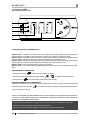
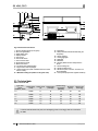
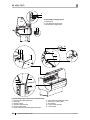
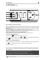
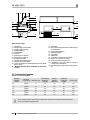
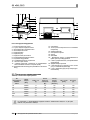
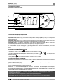
Rys.1 Budowa urządzenia 2
Rys.2 Usuwanie podestu drewnianego 3
Rys.3 Montaż półek ekspozycyjnych 4
Rys.4 Montaż elementów szklanych i lampy aluminiowej 4
Rys.5 Montaż/demontaż przysłonek nocnych 5
Rys.6 Pojemnik na skropliny 5
Rys.7 Panel sterowania 5
Rys.8 Demontaż szyby frontowej 6
Rys.9 Czujnik temperatury wewnątrz urządzenia 6
Rys.10 Czyszczenie skraplacza 7
Rys.11 Wymiana świetlówki w lampie 7
Rys.12 Tabliczka znamionowa 8
Rys.13 Panel termostatu „Igloo” 9
Rys.14 Panel termostatu „Carel” 10
1. ROZŁADUNEK 1
2. CHARAKTERYSTYKA WYROBU 1
2.1. Przeznaczenie 1
2.2. Opis urządzenia 1
2.3. Dane techniczne 2
3. PRZYGOTOWANIE URZĄDZENIA DO EKSPLOATACJI 3
3.1. Wymagania dotyczące miejsca instalacji 3
3.2. Podłączenie i uruchomienie 3
4. EKSPLOATACJA 5
4.1. Regulacja temperatury 6
5. KONSERWACJA 6
5.1. Czyszczenie i konserwacja 6
6. SERWIS 7
6.1. Identyfi kacja i naprawa usterek 7
6.2. Serwis 8
7. OBSŁUGA TERMOSTATU 9
7.1. Termostat „IGLOO” 9
7.2. Termostat „CAREL” 10
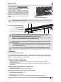
Tabela 1 Dane techniczne 2
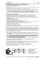
1. ROZŁADUNEK
Urządzenie powinno być transportowane w pozycji pionowej, odpowiednio zabezpieczone i spakowane. Producent wysy-
ła urządzenie na specjalnym podeście drewnianym, zabezpieczone tekturowymi kątownikami oraz folią.
2. CHARAKTERYSTYKA WYROBU
2.1. Przeznaczenie
Witryny „Monika 2, Rota” są uniwersalnymi urządzeniami chłodniczymi przeznaczonymi do przechowywania i ekspono-
wania szerokiego asortymentu artykułów spożywczych w opakowaniach jednostkowych, uprzednio wychłodzonych do
temperatury przechowywania. Nasze witryny zapewniają uniwersalną i efektywną przestrzeń wystawową dla wszelkiego
typu placówek handlowych i gastronomicznych. Gwarantowana temperatura wewnątrz witryn +2ºC/+8ºC przy tempera-
turze otoczenia +15ºC/+25ºC i wilgotności wzgl. powietrza do 60%.
2.2. Opis urządzenia
Witryny „Monika 2, Rota” posiadają chłodzenie statyczne. Wszystkie typy wyposażone są w odszranianie automatyczne
i elektroniczny termostat opcjonalnie współpracujący z modułem do rejestracji temperatury pozwalającym na rejestrację
i sygnalizację za wysokiej i za niskiej temperatury w urządzeniu. W opcji mogą również posiadać automatyczne odparo-
wanie kondensatu. Witryny „Monika 2, Rota” posiadają komorę przechowalniczą. Urządzenia „IGLOO” wykonywane są
w/g nowoczesnych technologii i posiadają wymagane prawem certyfi katy.
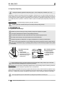
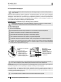
Tym znakiem oznaczone są informacje o szczególnym znaczeniu dla bezpieczeństwa użytkownika
oraz do prawidłowej eksploatacji urządzenia
Instrukcja obsługi
MONIKA 2, ROTA
pl

2
pl
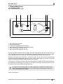
Instrukcja obsługi Monika 2, Rota www.igloo.pl
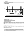
1 – Półka wydawcza na szybę
2 – Szyba frontowa gięta, uchylna
3 – Półka ekspozycyjna szklana
4 – Półki ekspozycyjne
5 – Ekran frontowy
6 – Odbojnica frontowa
7 – Półka frontowa dla klienta
8 – Podświetlany panel frontowy
9 – Podstawa urządzenia
10 – Lampa aluminiowa z podświetleniem
11 – Przysłonki nocne pleksi
12 – Blat roboczy granitowy (ze stali nierdzewnej lub płyty
meblowej w „Rocie”)
13 – Maksymalna linia załadunku (naklejka na boku szklanym!)
14 – Parownik
15 - Rynienka (odpływ kondensatu z odszraniania
parownika)
16 – Komora przechowalnicza
17 – Agregat chłodniczy
18 - Tabliczka znamionowa
19 – Boki ABS
20 – Podest drewniany zakładany do transportu
urządzenia
21 - Nóżki służące do wypoziomowania urządzenia
22 – Drzwi do komory przechowalniczej
23 – Wiatrownica (po ściągnięciu dostęp do lamel
skraplacza)
24 – Panel sterowania (regulator temperatury/wy-
łączniki)
2.3. Dane techniczne
Tabela 1 Dane techniczne
Typ urządzenia
„MONIKA”
„ROTA
Napięcie
znamion.
[V/Hz]
Prąd znamion.
[A]
Moc znamion.
oświetl.
[W]
Zużycie
energii elektr.
[kWh/24h]
Obciąż. półki
[kg/mb]
Waga urz.
[kg]
1.0 230/50 1,1 18 3,6 50 110
1.3 230/50 1,2 30 3,8 50 130
1.5 230/50 1,5 36 4,9 50 150
1.7 230/50 2,0 58 6,4 50 170
2.05 230/50 2,0 58 6,4 50 190
2.5 230/50 2,4 60 7,6 50 220
Rys.1 Budowa urządzenia
W urządzeniach z podświetlanym panelem frontowym moc znamionowa oświetlenia jest dwa razy
większa niż podana w tabeli!
12 11 10
13
1
16
15
14
24
2
18
19
23
20
22
21
3
5
9
6
8
7
4
17

3
pl
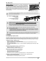
Instrukcja obsługi Monika 2, Rotawww.igloo.pl
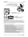
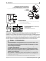
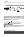
1 – Wykręcić nóżki z podestu
2 – Usunąć drewniany podest
3 – Wkręcić nóżki w nakrętki przyspawa-
ne do ramy urządzenia
Rys.2 Usuwanie podestu drewnianego
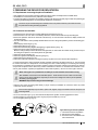
3. PRZYGOTOWANIE URZĄDZENIA DO EKSPLOATACJI
3.1. Wymagania dotyczące miejsca instalacji
• Sprawdź, czy przekrój przewodów zasilających jest odpowiedni dla poboru prądu instalowanego urządzenia
• Zabrania się podłączania urządzenia przez przewody przedłużające lub rozdzielacze
• Urządzenie należy podłączyć do oddzielnego, prawidłowo wykonanego obwodu elektrycznego z gniazdem wtykowym
z kołkiem ochronnym (w/g PBUE)
Uruchomienie urządzenia, może nastąpić tylko po potwierdzeniu skuteczności ochrony przeciwporaże-
niowej wynikami z pomiarów, przeprowadzonymi zgodnie z obowiązującymi przepisami!
3.2. Podłączenie i uruchomienie
• Rozpakować urządzenie i usunąć drewniany podest znajdujący się na podstawie Rys.2 (str.3)
• Urządzenie ustawić na równym i dostatecznie twardym podłożu, a następnie wypoziomować je za pomocą nóżek
• Ściągnąć folię ochronną z elementów witryny (m.in.: z wnętrza urządzenia, półek ekspozycyjnych, odbojnicy frontowej)
• Jeżeli urządzenie trafi do użytkownika częściowo zdemontowane dla zabezpieczenia w czasie transportu należy
wykonać następujące operacje:
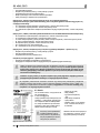
1. Założyć półki ekspozycyjne Rys.3/1 (str.4)
2. Zamontować boki szklane Rys.4/2;1 (str.4)
3. Zamontować lampę aluminiową (wraz z oświetleniem) na bokach szklanych Rys.4/3 (str. 4)
4. Założyć osłonę przewodu lampy Rys.4/10 (str.4) Osłonę przewodu nale
ży nasunąć na tył boku szklanego tak, aby
przewód wychodzący z lampy był ukryty w osłonie i znajdował się po wewnętrznej stronie boku szklanego!
5. Założyć ekran frontowy Rys.4/8 (str.4)
6. Zamontować szyby frontowe witryny Rys.4/5 (str.4)
7. Zamontować przysłonki nocne Rys.5/1;2 (str.5)
8. Podłożyć pojemnik na skropliny wg Rys.6/2 (str.5) (nie dotyczy urządzeń z wyparką!)
• Umieścić wtyczkę przewodu przyłączeniowego bezpośrednio w gnieździe wtykowym (zabrania się podłączania urzą-
dzenia przez przewody przedłużające lub rozdzielacze!)
Gniazdka sieciowe (opcja), mogą być przeznaczone do zasilania kasy fi skalnej, wagi itp. odbiorników
o mocy nie przekraczającej 500W!
• Załączyć przycisk wyłącznika głównego Rys.7/1 (str.5), co spowoduje załączenie termostatu, a następnie agregatu urządzenia
• Na panelu termostatu Rys.7/3(str.5) ustawić temperaturę (szczegóły obsługi na str.9 lub 10)
• Załączyć przycisk oświetlenia Rys.7/2 (str.5)
• Pierwsze mycie urządzenia powinno być wykonane po rozpakowaniu urządzenia i przed jego uruchomieniem. Urzą-
dzenie należy umyć wodą o temperaturze nieprzekraczającej 40ºC z dodatkiem neutralnych środków czyszczących.
Do mycia i czyszczenia urządzenia zabrania się stosowania środków zawierających chlor i sód różnych odmian,
które niszczą warstwę ochronną i elementy składowe urządzenia
!
Ewentualne pozostałości klejów czy silikonu
na elementach metalowych urządzenia usuwać wyłącznie benzyną ekstrakcyjną (nie dotyczy elementów z plastiku i
tworzyw sztucznych!). Nie wolno używać innych rozpuszczalników organicznych.
Podczas mycia urządzenia zabrania się używać strumienia wody. Urządzenie należy myć
przy użyciu wilgotnej ściereczki
Po zakończeniu instalacji urządzenia w miejscu docelowym należy pozostawić je w spoczynku, przez co
najmniej 2 godziny przed włączeniem (dotyczy urządzeń z agregatem wewnętrznym), aby poziom oleju
ustalił się, co zapobiegnie problemom z rozruchem agregatu chłodniczego!
OSTRZEŻENIE: Chronić przed uszkodzeniem obwód chłodniczy!
123

4
pl
Instrukcja obsługi Monika 2, Rota www.igloo.pl
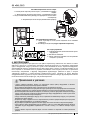
1
1 – Półka ekspozycyjna
2 – Kątownik aluminiowy przedni
3 – Kątownik aluminiowy tylny
1 – Docisk szyby (boku szklanego)
2 – Bok szklany
3 – Lampa aluminiowa
4 – Zaślepka lampy aluminiowej
5 – Szyba frontowa gięta, uchylna
6 – Profi l aluminiowy górny (prowadnica uchylna) szyby
7 – Profi l aluminiowy dolny (zawias szyby)
8 - Ekran frontowy, szklany
9 – Wspornik przedni
10 – Osłona przewodu lampy
11 – Przewód lampy
Rys.3 Montaż półek ekspozycyjnych
Rys.4 Montaż elementów szklanych i lampy aluminiowej
2
1
10
5
6
7
2
8
9
10
1
11
1
1
54
2
3
3

5
pl
Instrukcja obsługi Monika 2, Rotawww.igloo.pl
Rys.5 Montaż/demontaż przysłonek nocnych
1 – Przysłonka nocna dolna (krótsza) – montowana w pierwszej kolejności
2 – Przysłonka nocna górna (dłuższa) – montowana jako druga
3 – „Pióro” lampy aluminiowej (maskuje i zabezpiecza przysłonki nocne przed wypadaniem)
4 – Prowadnica przysłonek nocnych (profi l aluminiowy)
Rys.6 Pojemnik na skropliny
1 - Wąż spustu wody z rynienki (odpływ kondensatu z odszraniania parownika)
2 - Pojemnik na skropliny (należy opróżniać kondensat!!!)
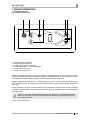
Rys.7 Panel sterowania
1 - Wyłącznik główny (załącza/wyłącza agregat urządzenia)
2 - Wyłącznik oświetlenia
3 - Panel termostatu
(szczegóły obsługi w Rozdziale nr 7 str.9 i 10)
4. EKSPLOATACJA
Temperatura chłodzonej przestrzeni i cykl pracy agregatu mogą ulegać wahaniom. Zależą one od wielu czynników
m. in. od ilości i temperatury włożonych produktów oraz od temperatury otoczenia.
Urządzenie należy ustawić w miejscu suchym, nienasłonecznionym, dobrze wentylowanym, zapewniającym dobrą
wymianę powietrza (dystans pomiędzy ścianą, a urządzeniem min. 10 cm), z dala od źródeł ciepła i urządzeń wymu-
szających przepływ powietrza (wentylatory sufi towe i przenośne, grzejniki nadmuchowe). Urządzenie funkcjonuje
poprawnie w środowisku, w którym temperatura zawiera się w odpowiedniej klasie klimatycznej podanej na tabliczce
znamionowej. Działanie urządzenia może ulec pogorszeniu, gdy przez dłuższy czas funkcjonować będzie w tempe-
raturze wyższej lub niższej w stosunku do podanego przedziału.
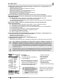
Uwagi i wskazówki
• Należy prawidłowo wypoziomować witrynę, co zapobiegnie hałaśliwej pracy urządzenia i zapewni prawidłowy
odpływ wody (kondensatu) podczas odszraniania
• Pierwsze zapełnienie przestrzeni chłodniczej dokonywać po uprzednim jej wychłodzeniu do temperatury pra-
cy. Zasada ta powinna być także przestrzegana po dłuższej przerwie w eksploatacji
• Nie blokować żadnych otworów wentylacyjnych, co mogłoby utrudnić cyrkulację schłodzonego powietrza.
Należy zapewnić również prawidłowy obieg powietrza wokół urządzenia (w żadnym wypadku nie wolno za-
krywać otworów wentylacyjnych agregatu)
• Należy zapewnić równomierne obciążenie półek, nie przekraczać ich maksymalnego obciążenia i nie przekra-
czać maksymalnego załadunku
• Utrzymywać skraplacz w czystości. Zanieczyszczenia mogą spowodować przegrzanie sprężarki i w efekcie
doprowadzić do awarii urz
ądzenia, co nie jest objęte gwarancją.
• Wewnątrz komory do przechowywania produktów żywnościowych nie używać przyrządów elektrycznych
12 3
1
2
3
4
2
1
1
1
2
2

6
pl
Instrukcja obsługi Monika 2, Rota www.igloo.pl
4.1. Regulacja temperatury
Obsługa termostatów (regulatorów temperatury) „Igloo” i „Carel” znajduje się w rozdziale 7 (str. 9 i 10)
Podstawowym zadaniem termostatu jest sterowanie agregatem chłodniczym tak, aby uzyskać zadaną temperaturę we-
wnątrz urządzenia i utrzymywać ją w określonych przedziałach. Wszystkie nastawy regulatora temperatury konieczne do
normalnego funkcjonowania urządzenia są wprowadzone przez producenta. Użytkownik przed pierwszym uruchomie-
niem urządzenia powinien sprawdzić i ewentualnie ustawić na panelu termostatu żądaną temperaturę wewnątrz urzą-
dzenia.
Cyfrowy wyświetlacz – wyświetla bieżącą temperaturę wewnątrz urządzenia
Wszelka ingerencja w ustawienia fabryczne termostatu powoduje utratę gwarancji!
5. KONSERWACJA
5.1. Czyszczenie i konserwacja
Wszelkie czynności konserwacyjne należy prowadzić po odłączeniu urządzenia od napięcia!
Chronić przed uszkodzeniem lub zalaniem wodą instalację elektryczną
Do czyszczenia urządzenia nie należy używać strumienia wody, a jedynie wilgotnej ściereczki
Nie należy stosować żadnych ostrych przedmiotów celem usuwania zabrudzeń!
Urządzenia wyposażone w kółka jezdne nie mogą być eksploatowane na nierównych powierzchniach!
Podczas mycia wnętrza urządzenia nie wolno zostawiać szyby frontowej swobodnie uchylonej w profi lu aluminio-
wym. Grozi to uszkodzeniem szyby i nie podlega gwarancji. Szybę na czas konserwacji wyciągnąć wraz z profi lem
Rys.8 (str.6).
3
2
1
Rys.8 Demontaż szyby
frontowej
1 - Szyba frontowa
2 - Profi l aluminiowy górny
(prowadnica uchylna) szyby
3 - Profi l aluminiowy dolny
(zawias) szyby
Rys.9 Czujnik temperatury
wewnątrz urządzenia
1 – Czujnik temperatury
2 – Przysłonka parownika
3 – Rynienka ociekowa
parownika
Podczas eksploatacji witryny jak również podczas prac konserwatorskich należy uważać, aby nie uszkodzić
czujnika temperatury znajdującego się w przysłonce parownika!
Raz na miesiąc zaleca się przerwę w eksploatacji urządzenia celem oczyszczenia jego wnętrza, naturalnego odszronie-
nia parownika, oczyszczenia skraplacza i sprawdzeniu stanu uszczelek drzwi.
Jeżeli urządzenie nie posiada automatycznego odparowania kondensatu należy usuwać kondensat z pojemnika w przy-
padku jego napełnienia Rys.6 (str.5). Ilość (częstotliwość) usuwania kondensatu zależy od warunków eksploatacji urzą-
dzenia (m.in. od wilgotności powietrza, częstotliwości otwierania drzwi, od ilości i temperatury wkładanych produktów).
W celu przyspieszenia procesu odszraniania nie posługiwać się środkami mechanicznymi!
123

7
pl
Instrukcja obsługi Monika 2, Rotawww.igloo.pl
Skraplacz urządzenia należy utrzymywać w czystości. Zanieczyszczenia
utrudniają wymianę ciepła, powodując m. in. wzrost zużycia energii elektrycz-
nej i mogą spowodować uszkodzenie sprężarki agregatu. Aby wyczyścić skra-
placz należy wykręcić blachowkręty mocujące i ściągnąć wiatrownicę. Lamele
skraplacza czyścić za pomocą miękkiej szczotki lub pędzla. Przy mocnym za-
brudzeniu (zapchaniu lamel) skraplacza wskazane jest użycie odkurzacza lub
sprężonego azotu w celu odessania / wydmuchania zabrudzeń znajdujących
się miedzy lamelami.
Za uszkodzenia agregatu skraplającego powstałe w wyniku nieprzestrzegania czystości skraplacza pro-
ducent nie ponosi odpowiedzialności!
Uszczelkę drzwi należy czyścić wyłącznie czystą wodą bez dodatku środków myjących i pamiętać o jej
dokładnym wysuszeniu. Uszczelka nie może mieć kontaktu z substancjami tłustymi ani olejami!
Podczas czynności konserwujących należy sprawdzić czy drzwi zamykają się właściwie.
Próba: umieścić kartkę papieru pomiędzy uszczelką,
a obudową i zamknąć drzwi. Papier powinien stawiać wyczuwalny opór przy próbie wyciągania
6. SERWIS
6.1. Identyfi kacja i naprawa usterek
W przypadku wystąpienia jakichkolwiek trudności podczas uruchamiania urządzenia lub podczas jego eksploatacji należy
powrócić do tych rozdziałów instrukcji obsługi, które wyjaśniają wykonywaną operacje. Ma to na celu upewnienie się, czy
urządzenie jest prawidłowo obsługiwane. Jeżeli trudności występują nadal, poniższe wskazówki pomogą w ich usunięciu.
• Urządzenie nie pracuje...- Upewnić się, czy:
• Urządzenie jest podłączone do sieci prądu elektrycznego
• Napięcie i częstotliwość w sieci są odpowiednie z tymi, jakie zaleca producent (patrz tabliczka znamionowa)
• Włączony jest wyłącznik główny
• Termostat jest załączony (Dotyczy term. Igloo – Jeśli na wyświetlaczu wyświetlają się jedynie dwie kropki – włącz
termostat)
Urządzenie pracuje, oświetlenie nie świeci...- Upewnić się, czy:
• Wyłącznik oświetlenia jest w pozycji załączonej
• Świetlówka lub zapłonnik w urządzeniu nie uległy spaleniu
Wycieka woda spod urządzenia lub do wnętrza komory
• Sprawdzić prawidłowość wypoziomowania urządzenia
• Sprawdzić drożność przewodów odpływowych
• Opróżnić pojemnik lub tack
ę na skropliny
• Sprawdzić czy w rynience i na parowniku nie zalega duża ilość lodu – w razie potrzeby odszronić
Urządzenie nie osiąga odpowiedniej temperatury, oświetlenie świeci...- Upewnić się, czy:
• Wyłącznik główny jest w pozycji załączonej
• Nastawa temperatury na termostacie jest odpowiednio ustawiona
Rys.11 Wymiana świetlówki w lampie
1 – Uchwyt świetlówki
2 – Świetlówka
3 – Oprawa świetlówki i zapłonnika
4 – Zapłonnik świetlówki
Rys.10 Czyszczenie skraplacza
Elementy urządzenia mogą korodować przy niewłaściwym użytkowaniu i konserwacji.
Należy przestrzegać zasad:
• Nie dopuszczać do kontaktu powierzchni urządzenia z środkami zawierającymi chlor i/lub sodę
w różnych odmianach, które niszczą ich warstwę ochronną i elementy składowe urządzenia
(dotyczy również różnych gatunków stali nierdzewnej)
Podczas czynności konserwujących należy uważać, aby nie uszkodzić tabliczki znamionowej urządzenia Rys.12
(str.8), która zawiera istotne informacje dla serwisantów oraz fi rm zajmujących się usuwaniem odpadów.
34
21

8
pl
Instrukcja obsługi Monika 2, Rota www.igloo.pl
• Numer seryjny (NS)
• Datę produkcji
• Typ (nazwa urządzenia)
oraz
• Datę zakupu urządzenia
• Opis problemu
• Dokładny adres i numer telefonu
wraz z numerem kierunkowym
do Państwa
• Termostat działa poprawnie
• Skraplacz nie jest zanieczyszczony, w razie potrzeby wyczyścić
• Temperatura otoczenia nie jest wyższa niż 25ºC
• Minęło wystarczająco dużo czasu dla schłodzenia produktów
• Otwory wentylacyjne urządzenia nie są zablokowane
(Dotyczy term. „IGLOO”) Termostat wyświetla C0 lub C1 lub C2 zamiast temperatury:
Sytuacja taka ma miejsce, jeżeli został uszkodzony jeden z czujników regulatora wówczas mogą pojawić się
następujące komunikaty:
• C0 –uszkodzenie czujnika temperatury wewnątrz komory –wezwać autoryzowany serwis
• C1 –uszkodzenie czujnika parownika - wezwać autoryzowany serwis
•
C2 –uszkodzenie czujnika alarmu skraplacza (lub uszkodzenie drugiego czujnika parownika) – wezwać autoryzowany
serwis
(Dotyczy term. „CAREL”) Termostat wyświetla E0 lub E1 lub L0 lub HI lub EE lub Ed lub DF zamiast temperatury:
• E0 -uszkodzenie czujnika temperatury wewnątrz komory- wezwać autoryzowany serwis
• E1 -uszkodzenie czujnika parownika - wezwać autoryzowany serwis
• L0 –alarm niskiej temperatury (niższej niż zadany zakres wewnątrz urządzenia) - wezwać autoryzowany serwis
• HI - alarm wysokiej temperatury - wezwać autoryzowany serwis
• EE -błąd wewnętrzny regulatora - wezwać autoryzowany serwis
• Ed – przekroczenie max. czasu odszraniania
• DF – odszranianie w toku (to nie jest sygnał alarmowy)
(Dotyczy term. „IGLOO”) Urządzenie pracuje, włączona sygnalizacja dźwiękowa...- Upewnić się, czy
• Skraplacz nie jest zanieczyszczony, w razie potrzeby wyczyścić
• Pracuje wentylator skraplacza
• Temperatura otoczenia nie przekracza 25ºC
Urządzenie pracuje zbyt głośno...- Upewnić się, czy
• Urządzenie stoi stabilnie i jest prawidłowo wypoziomowane
• Przylegające do urządzenia meble nie drgają podczas pracy sprężarki agregatu chłodniczego
Odgłosy wydawane przez urządzenia pracujące są zjawiskiem normalnym. W urządzeniach znajdują się
wentylatory, silniki i sprężarki, które włączają się i wy
łączają automatycznie. Każda sprężarka wytwarza
pewien hałas podczas pracy. Dźwięki te wytwarzane są przez silnik agregatu oraz przez czynnik
chłodniczy przepływający w obwodzie. Zjawisko to jest cechą techniczną urządzeń chłodniczych i
nie oznacza ich wadliwej pracy.
Osadzanie się pary wodnej na szybach urządzenia przy dużej wilgotności względnej powietrza
powyżej 60% jest zjawiskiem naturalnym i nie wymaga wzywania serwisu!
Rys.12 Tabliczka znamionowa
6.2. Serwis
Tel. do serwisu IGLOO: +48 (14) 662 19 56
lub +48 605 606 071
e-mail: [email protected]
Jeśli po sprawdzeniu punktów opisanych w
rozdziale 6.1 „Identyfi kacja i naprawa uste-
rek” urządzenie nadal nie działa prawidło-
wo, należy skontaktować się z Serwisem
Technicznym fi rmy Igloo, podając dane z
tabliczki znamionowej Rys.12 (str.8)
Powyższy rysunek przedstawia
poglądową tabliczkę znamio-
nową, a dane w niej zawarte są
danymi przykładowymi nieodno-
szącymi się do „Moniki 2”!
Tabliczka znamionowa znajduje się z
tyłu urządzenia, w prawym, górnym
rogu poniżej blatu Rys.1/18 (str.2)
W przypadku przekroczenia warunków otoczenia wg trzeciej klasy klimatycznej (wilgotność
względna powietrza powyżej 60%) może występować zjawisko przelewania wody z układu z au-
tomatycznym odparowaniem kondensatu (wyparki). Przypadek ten nie oznacza wadliwej pracy
urządzenia i nie wymaga wzywania serwisu.

9
pl
Instrukcja obsługi Monika 2, Rotawww.igloo.pl
7. OBSŁUGA TERMOSTATU
7.1. Termostat „IGLOO”
Rys.13 Panel termostatu "Igloo"
Sprawdzanie nastawionej temperatury (wewnątrz urządzenia) – Naciskając przycisk „▲” lub „▼” jeden raz możemy
sprawdzić nastawioną temperaturę. Na wyświetlaczu pojawia się nastawiona temperatura, przy której świeci się czerwo-
na mrugająca kropka (dioda). Wyjście z podglądu następuje automatycznie po ok. 3 sekundach.
Obniżenie (lub podwyższenie) temperatury – naciskamy przycisk „▼” (lub „▲”) i na panelu pojawi się ustawiona tempe-
ratura. Naciskając przycisk „▼” obniżamy temperaturę do żądanej wartości. Wyjście z funkcji następuje automatycznie
po ok. 3 sek.
Ręczne odszranianie –przycisk nr 2 pozwala na włączenie cyklu odszraniania w dowolnym momencie pracy urządzenia
(niezależnie od funkcji automatycznego odszraniania); przycisk nie działa, gdy temperatura jest wyższa niż temperatura
końca odszraniania
Zaleca się, aby użytkownik załączał/wyłączał agregat korzystając jedynie z wyłą
cznika głównego urzą-
dzenia, a nie z przycisku bezpośrednio na panelu termostatu. Załączenie wyłącznika głównego automa-
tycznie załącza termostat!
* Więcej na stronie www.igloo.pl
1 – Przycisk włącz/wyłącz chłodzenie
2 – Przycisk ręcznego odszraniania
3 – Kontrolka pracy agregatu i odszraniania
4 - Przycisk podglądu temp. na czujniku odszraniania
5 – Przycisk zmiany temp. do góry
6 – Przycisk zmiany temp. w dół
2134 65

10
pl
Instrukcja obsługi Monika 2, Rota www.igloo.pl
7.2. Termostat „CAREL”
Rys.14 Panel termostatu "Carel"
CO OZNACZAJĄ DIODY NA WYŚWIETLACZU
Zapalona dioda 1 - Sprężarka: symbol jest widoczny, gdy sprężarka pracuje. Miga, gdy start sprężarki jest opóźniony
przez procedurę ochronną. Miga w cyklu: dwa mignięcia – przerwa, gdy uruchomiony jest tryb pracy ciągłej.
Zapalona dioda 2 - Wentylator: symbol jest widoczny, gdy włączone są wentylatory parownika. Miga, gdy start wentyla-
torów jest opóźniony poprzez zewnętrzne wyłączenie lub, podczas gdy inna procedura jest w toku.
Zapalona dioda 3 - Odszranianie: symbol jest widoczny, gdy włączona jest funkcja odszraniania. Miga, gdy start odszra-
niania jest opóźniony poprzez zewnętrzne wyłączenie lub podczas, gdy inna procedura jest w toku.
Zapalona dioda 4 - Alarm: symbol jest widoczny, gdy aktywny jest alarm
Zapalona dioda 5 – wyświetlana bieżąca temperatura wewnątrz urządzenia (po przecinku wyświetlane miejsca dzie-
siętne)
NASTAWA ŻĄDANEJ TEMPERATURY
- naciśnij przez 1 sekundę
: wartość wodząca pojawi się na ekranie;
- zwiększ lub zmniejsz wartość wodzącą używając klawiszy
i , aż osiągniesz pożądaną wartość;
- naciśnij ponownie
w celu potwierdzenia nowej wartości punktu nastawy;
RĘCZNE WYMUSZENIE CYKLU ODSZRANIANIA
Odszranianie realizowane jest w sposób automatyczny. Można jednak w dowolnej chwili wymusić odszranianie poprzez
naciśnięcie i przytrzymanie przycisku
przez minimum 5 sekund. Podczas ręcznego odszraniania miga dioda 1.
* Więcej na stronie www.alfaco.pl
UWAGA: W PRZYPADKU NIE ZASTOSOWANIA SIĘ DO ZASAD ZAWARTYCH W NINIEJSZEJ INSTRUKCJI DO-
TYCZĄCYCH PODŁĄCZENIA I EKSPLOATACJI URZĄDZENIA, PRODUCENT ZASTRZEGA SOBIE PRAWO OD-
STĄPIENIA OD OBOWIĄZKÓW GWARANTA!!!
Informacje zawarte w tym dokumencie mogą być zmienione przez „IGLOO” bez powiadamiania użytkownika.
Kopiowanie niniejszej instrukcji bez zgody producenta jest zabronione.
Zdjęcia oraz rysunki mają charakter poglądowy i mogą się różnić od zakupionego urządzenia.
1
2
3
4
5

en
11
User manual Monika 2, Rotawww.igloo.pl
Fig.1 Construction of the device 12
Fig.2 Removing the wooden platform 13
Fig.3 Assembly of display shelves 14
Fig.4 Assembly of glass elements and aluminium lamp 14
Fig.5 Assembly/ disassembly of night screens 15
Fig.6 Condensate container 15
Fig.7 Control panel 15
Fig.8 Front glass disassembly 16
Fig.9 Temperature sensor inside the device 16
Fig.10 Cleaning the condenser 17
Fig.11 Changing the fl uorescent lamp 17
Fig.12 Data plate 18
Fig.13 „Igloo” thermostat control panel 19
Fig.14 „Carel” thermostat control panel 20
1. UNLOADING
The device should be transported in vertical position, and it should be properly secured and packed. The manufacturer
ships the device on a special wooden platform, secured with cardboard angle sections and foil.
2. PROPERTIES OF THE DEVICE
2.1. Purpose
“Monika 2, Rota” is a universal cooling device used to store and display a wide assortment of grocery products in singular
packages, previously cooled to storage temperature. Our display cabinets ensure universal and effi cient display area for
all types of commercial and gastronomic units. Guaranteed temperature inside the display cabinet equals +2ºC/+8ºC with
ambient temperature of +15ºC/+25ºC and relative air humidity of up to 60%.
2.2. Description of the device
“Monika 2, Rota” display cabinet has static cooling. All types are equipped with automatic defrosting and electronic ther-
mostat optionally cooperating with temperature recording module enabling to record and signal too low and too high
temperature within the device. There is also an option with automatic condensate evaporation. “Monika 2, Rota” display
cabinet is furnished with a storage chamber. Our devices are made according to modern technologies and have all cer-
tifi cates required by law.
This sign signifi es information of particular meaning for user security and for proper device
exploitation.
Contents List of Figures
List of tables
Table 1 Technical data 12
User manual MONIKA 2, ROTA
1. UNLOADING 11
2. PROPERTIES OF THE DEVICE 11
2.1. Purpose 11
2.2. Description of the device 11
2.3. Technical data 12
3. PREPARING THE DEVICE FOR EXPLOITATION 13
3.1. Requirements concerning the place of installation 13
3.2. Connection and actuation 13
4. EXPLOITATION 15
4.1. Temperature regulation 16
5. MAINTENANCE 16
5.1. Cleaning and maintenance 16
6. SERVICE 17
6.1. Fault identifi cation and repair 17
6.2. Service 18
7. THERMOSTAT SERVICE 19
7.1. „IGLOO” thermostat 19
7.2. „CAREL” thermostat 20
en

en
12
User manual Monika 2, Rota www.igloo.pl
1 – Shelf for handling goods (on the glass)
2 – Bent, front glass, lifted
3 – Glass display shelf
4 – Display shelves
5 – Front screen
6 – Front fender beam
7 – Front customer shelf
8 – Illuminated front panel
9 – Basis of the device
10 – Aluminium lamp with illumination
11 – Night screens made of plexiglas
12 – Granite working top (made of stainless steel or furniture
board in “Rota”)
13 – Maximum loading line (sticker on the glass side!)
14 – Evaporator
15 – Rail (condensate outfl ow after defrosting the
evaporator)
16 – Storing chamber
17 – Cooling aggregate
18 – Data plate
19 – ABS sides
20 – Wooden platform fi xed for transport of the
device
21 – Device levelling feet
22 – Storage chamber doors
23 – Wind brace (when removed – access to con-
denser lamellas)
24 – Control panel (temperature regulator /switches)
2.3. Technical data
Table 1 Technical data
Type of the
device
„MONIKA” „ROTA
Rated voltage
[V/Hz]
Rated current
[A]
Rated lighting
power [W]
Electric energy
consumption
[kWh/24h]
Shelf load
[kg/mb]
Weight of the
device [kg]
1.0 230/50 1,1 18 3,6 50 110
1.3 230/50 1,2 30 3,8 50 130
1.5 230/50 1,5 36 4,9 50 150
1.7 230/50 2,0 58 6,4 50 170
2.05 230/50 2,0 58 6,4 50 190
2.5 230/50 2,4 60 7,6 50 220
Fig.1 Construction of the device
In devices with illuminated front panel, the rated lighting power is twice bigger than the one stated in
the table!
12 11 10
13
1
16
15
14
24
2
18
19
23
20
22
21
3
5
9
6
8
7
4
17

en
13
User manual Monika 2, Rotawww.igloo.pl
1 – Unscrew the feet from the platform
2 – Remove the wooden platform
3 – Screw the feet in nuts welded to the
frame of the device
Fig.2 Removing the wooden platform
3. PREPARING THE DEVICE FOR EXPLOITATION
3.1. Requirements concerning the place of installation
• Verify whether the cross section of feeding conduits is proper for power consumption of the installed device.
• It is forbidden to connect the device by extension rods or dividers.
• The device should be connected to the separate, properly made electric circuit with plug-in socket with protecting pin
(according to PBUE /Regulations concerning Electric Equipment Construction/)
The device may be actuated solely after confi rmation of the fi re protection effi ciency with results of measu-
res performed according to binding regulations!
3.2. Connection and actuation
• Unpack the device and remove the wooden platform from the basis Fig.2 (p.13)
• Place the device on an even and on a suffi ciently hard base, and then level it with the help of levelling feet.
• Remove the protection foil from the elements of the device (f. ex. from the inside of the device, display shelves and
front fender beam)
• If the user shall obtain a device partially disassembled to secure it during transportation, perform the following ope-
rations:
1. Mount display shelves Fig.3/1 (p.14)
2. Mount glass sides Fig.4/2;1 (p.14)
3. Mount the aluminium lamp (together with lighting) on glass sides Fig.4/3 (p. 14)
4. Mount the casing of lamp conduit Fig.4/10 (p.14)
Move the casing of lamp conduit to the back of the glass side, in order to hide the conduit coming out of the lamp in
the casing and to place it on the internal part of the glass side!
5. Mount front screen Fig.4/8 (p.14)
6. Mount front glasses of the display cabinet Fig.4/5 (p.14)
7. Mount night screens Fig.5/1;2 (p.15)
8. Place the condensate container according to Fig.6/2 (p.15) (does not concern devices with evaporator!)
• Place the plug of the connecting cable directly in plug-in socket (it is forbidden to connect the device by means
of extension cords or dividers!)
Power sockets (optional) may be used to power cash register, weight, and similar receivers with power not
exceeding 500W!
• Turn on the main switch Fig.7/1 (p.15), which activates the temperature regulator, and then aggregate of the device
• Set the temperature on thermostat control panel Fig.7/3(p.15) (service details on p.19 or 20)
• Turn on the lighting switch Fig.7/2 (p.15)
• The fi rst cleaning of the device should be provide right after unpacking, and before turning it on. The unit should
be cleaned with water at a temperature not exceeding 40°C with a neutral detergent. For washing and cleaning
the equipment it is prohibited to use products containing chlorine and sodium varieties, which destroy the protecti-
ve layer and components of the device! Any residue of adhesives or silicone on metal elements should be remo-
ved only with extraction naphtha (not applicable to items made of plastic !). Do not use other organic solvents.
When cleaning the unit is prohibited to use water jet. The unit should be cleaned with a wet rag.
After installation of the device at the destination place it should be left to rest for at least 2 hours before
turning it on (for devices with built in compressor) to set the level of refrigerant in order to prevent problems
with starting up the aggregate.
WARNING: Keep out the cooling circuit from damage!
123

en
14
User manual Monika 2, Rota www.igloo.pl
1 – Display shelf
2 – Front aluminium angle section
3 – Back aluminium angle section
1 – Pressure of the glass (glass side)
2 – Glass side
3 – Aluminium lamp
4 – Aluminium lamp hole plug
5 – Bent front glass, lifted
6 – Upper aluminium profi le (lifted guide) of the glass
7 – Lower aluminium profi le (glass catch)
8 – Front screen, made of glass
9 – Front bracket
10 – Lamp conduit protection
11 – Lamp conduit
Fig.3 Assembly of display shelves
Fig.4 Assembly of glass elements and aluminium lamp
1
2
1
10
5
6
7
2
8
9
10
1
11
1
1
54
2
3
3

en
15
User manual Monika 2, Rotawww.igloo.pl
4. EXPLOITATION
Temperature of the cooled space and aggregate operating cycle may fl uctuate. They depend on numerous factors,
such as amount and temperature of products placed in the device and temperature of the surroundings.
The device should be placed in a dry and well-ventilated place, ensuring proper air exchange (distance between the
wall and the device – min. 10 cm), out of sunlight, kept far from heat sources and devices enforcing air fl ow (ceiling
and portable ventilators, blow-in heaters). The device functions properly in a room, where temperature falls within
appropriate climatic class stated on the data plate. The operation of the device may worsen when it shall operate in
temperature lower or higher than the stated temperature range.
Remarks and indications
• It is necessary to properly level the display cabinet, which will prevent loud operation of the device and shall
ensure proper water (condensate) outfl ow during defrosting.
• After transporting the device, wait about 2 hours before its actuation.
• The fi rst fi lling of cooling space should be performed after its previous cooling to working temperature. This
principle should also be observed after longer pause in exploitation.
• Do not block any ventilation holes, which would hamper circulation of the cooled air. It is also necessary to
ensure proper airfl ow around the device (aggregate ventilation holes cannot be covered).
• Ensure even load on shelves, do not exceed their maximal load and do not exceed maximal loading.
• Keep the condenser clean. Impurities may lead to overheating of the compressor and as a consequence may
result in damage of the device, which is not covered by warranty.
• Do not use electric devices inside grocery product storing chamber.
• After closing the door of the device, it is not recommended to open it with force. Negative pressure created
inside the device is levelled within 1-2 minutes, which allows easy opening of the door.
• Avoid unnecessary opening of doors and leaving them open for a longer period of time.
12 3
1
2
3
4
2
1
1
1
2
2
Fig.5 Assembly/disassembly of night screens
1 – Lower night screen (shorter one) – mounted as the fi rst one
2 – Upper night screen (longer one) – mounted as the second one
3 – “Leaf” of the aluminium lamp (hides and secures the night screens before
falling out)
4 – Night screen guide (aluminium profi le)
Fig.6 Condensate container
1 – Rail water outlet hose (condensate outfl ow after condenser evaporation)
2 – Condensate container (empty the condensate!!!)
Fig.7 Control panel
1 – Main switch (turns on/off the aggregate of the device)
2 – Lighting switch
3 – Thermostat (temperature regulator) panel
(service details in Chapter No.7 p.19 and 20)

en
16
User manual Monika 2, Rota www.igloo.pl
4.1. Temperature regulation
Service of “Igloo” and “Carel” thermostat (temperature regulators) is described in chapter 7 (p.19 and 20)
The basic aim of a thermostat is to control the cooling aggregate to obtain the set temperature within the device and
maintain it within the determined temperature ranges. The producer enters all settings of temperature regulators required
for normal functioning of the device. Before primary actuation the user should control and possibly set the required tem-
perature inside the device on the control panel.
Digital display – displays the current temperature inside the device.
It is forbidden to interfere with systemic parameters of the thermostat, as this can lead to serious consequ-
ences, including the damage of the cooling device!
5. MAINTENANCE
5.1. Cleaning and maintenance
All maintenance services need to be performed after disconnecting the device from power supply!
Protect electric installation against any damage or water spillage
Do not use water stream to clean the device, only a wet cloth
Do not use any sharp objects to remove fi lth!
Devices equipped with wheels cannot be used on uneven surfaces!
During cleaning the inside of the device do not leave the front glass freely lifted in the aluminium profi le. This may
cause the damage of the glass and is not covered by warranty. Please remove the glass with profi le for the time of
cleaning Fig.8 (p.16).
Fig.8 Front glass
disassembly
1- Front glass
2- Upper aluminium profi le
(lifted guide) of the glass
3- Lower aluminium profi le
(catch) of the glass
Fig.9 Temperature sensor
inside the device
1 – Temperature sensor
2 – Evaporator screen
3 – Evaporator drip rail
When using the display cabinet, as well as during maintenance works, pay attention not to destroy the tempe-
rature sensor in the evaporator screen!
It is recommended to make a break in the exploitation of the device once a month in order to clean its interior,
naturally defrost the evaporator, clean the condenser and verify the condition of door seals.
If the device is not equipped with automatic condensate evaporation, it is essential to remove the condensate from the
container when fi lling the container Fig.6 (p.15). The number (frequency) of condensate removal depends on device
exploitation conditions (f. ex. air humidity, door opening frequency, the amount and temperature of products placed for
storage).
Do not use mechanical agents in order to fasten the defrosting process!
3
2
1
123

en
17
User manual Monika 2, Rotawww.igloo.pl
It is essential to keep the condenser of the device cle-
an. Dirt may hinder the heat exchange, causing mainly
increase in electric energy consumption and may cause
damage of aggregate compressor.
In order to clean the condenser it is necessary to
unscrew the sheet metal screws and pull the wind brace
out. Clean condenser lamellas with help of soft brush or
paint brush. If the condenser is extremely dirty (blocked
lamellas) it is indicated to use vacuum cleaner or com-
pressed nitrogen to suck / blow the dirt from between
lamellas.
The producer shall not be held responsible for damages of the condenser aggregate resulting from non-
observance of condenser cleanliness!
Door seal should be cleaned solely with clean water without any cleansing agents and it sho-
uld be thoroughly dried. The seal cannot get into contact with oily substances or grease!
Control whether door close properly during maintenance procedures.
Test: place a sheet of paper between the seal and the casing and close the door. The paper
should pose a tangible resistance during an attempt to pull it out.
During maintenance services it is necessary to pay attention not to damage the data place of the device
Fig.12 (p.18), which contains signifi cant information for servicing organs and waste removal companies.
6. SERVICE
6.1. Fault identifi cation and repair
In case of any diffi culties during actuation of the device or during its exploitation, please return to these chapters in this ma-
nual, which explain the performed operation. This aims to ensure that the device is properly operated. If you still experience
diffi culties, the following hints will help you solve the problem.
The device is not working... – Make sure that:
• The device is connected to the supply network
• Voltage and frequency in the network are compliant with those recommended by the producer, 230V/50Hz
• The main switch is turned on
• Thermostat is turned on (This concerns the Igloo thermostat – If only two spots are visible on the display – turn on
the thermostat)
The device is operating, but the lighting is off...– Make sure that:
• Lighting switch is turned on
• Fluorescent lamp or starting switch of the device are not burnt
Water leakage from below the device or into the inside of the chamber:
• Check whether the device is properly levelled
• Check the patency of outfl ow pipes
• Empty the condenser tray or container
• Check whether there is not too much ice in the rail and on the condenser – defrost when necessary
Fig.10 Cleaning the condenser
Elements of device can corrode when improper used and maintenance. To avoid that please
follow the rules:
• Do not allow contact of the surface of the device with substances containing chlorine and / or baking
soda in different varieties, which destroy the protective layer and components of the device (also
includes various stainless steel)
Fig.11 Changing the fl uorescent lamp
1 – Fluorescent lamp handle
2 – Fluorescent lamp
3 – Casing of fl uorescent lamp and
starting switch
4 – Starting switch of fl uorescent lamp
34
21

en
18
User manual Monika 2, Rota www.igloo.pl
The device does not reach the proper temperature, the lighting is on...– Make sure that:
• The main switch is on
• Temperature setting on the thermostat is properly set
• Thermostat works properly
• The condenser is clean, if necessary – clean the condenser
• Ambient temperature does not exceed 25ºC
• Enough time has passed for products to be cooled
• Ventilation holes of the device are not blocked
(This concerns the “IGLOO” thermostat) thermostat displays C0 or C1 or C2 instead of displaying temperature:
This situation shall occur, when one of temperature regulation sensors has been destroyed.
The following messages may be displayed in such case:
• C0 – temperature sensors inside the chamber are damaged – call authorized service
• C1 – failure of evaporator sensor - call authorized service
• C2 – failure of condenser alarm sensors (or failure of second evaporator sensor) – call authorized service
(This concerns the “CAREL” thermostat) Thermostat displays E0 or E1 or L0 or HI or EE or Ed or DF instead
of temperature:
• E0 – failure of temperature sensor inside the chamber – call authorized service
• E1 – failure of evaporator sensor – call authorized service
• L0 – low temperature alarm (lower than temperature range set within the device – call authorized service
• HI – high temperature alarm – call authorized service
• EE – internal defect of the regulator – call authorized service
• Ed – max. defrosting time exceeded
• DF – defrosting in progress (this is not an alarm signal)
(This concerns the “IGLOO” thermostat) The device is working, sound signalling is activated...– Make sure that:
• The condenser is clean, if necessary – clean the condenser
• Condenser ventilator is working properly
• Ambient temperature does not exceed 25ºC
The device is working too loud...– Make sure that:
• The device is standing stably
• Furniture adjoining the device do not vibrate when the cooling aggregate compressor is working
Noises made by the operating device are a normal phenomenon. The devices are equipped with venti-
la
tors, engines and compressors, which turn on and off automatically. Each compressor makes certain noises
when operating. These sounds are made by the aggregate engine and by cooling agent fl owing through the cir-
cuit. This phenomenon constitutes a technical feature of cooling devices and it does not signify their faulty work.
Steam precipitation on glasses of the device is a normal phenomenon in case of high relative air
humidity exceeding 60% and does not require calling the service!
• Serial number (NS)
• Production date
• Type (name of the device)
and
• Date when the device was
purchased
• Description of the problem
• Your exact address and telephone
number (with the code number)
Fig.12 Data plate
6.2. Service
IGLOO service telephone number:
+48 (14) 662 19 56 or +48 605 606 071
e-mail: [email protected]
If after checking points described in chapter
6.1 “Fault identifi cation and repair” the
device still does not work properly, please
contact Technical Service of the Igloo
company, stating the data from the data
plate Fig.12 (p.18):
The above fi gure shows a demon-
strative data plate and the data stated
on the plate are exemplary data,
which are not related with “Monika 2,
Rota” device!
The data plate is located at the back
of the device, in the upper right cor-
ner, below the top Fig.1/18 (p.12)

en
19
User manual Monika 2, Rotawww.igloo.pl
7. THERMOSTAT SERVICE
7.1. „IGLOO” thermostat
Fig.13 „Igloo” thermostat control panel
Verifi cation of adjusted temperature (inside the device) – By pressing “▲” or “▼” switch once we can verify the adjusted
temperature. The adjusted temperature shall be shown on the display with a visible red blinking spot (diode). The preview
shall fi nish automatically after about 3 seconds.
Lowering (or increasing) the temperature – press “▼” (or “▲”) switch and the adjusted temperature shall be visible on
control panel. By pressing the “▼” switch we decrease the temperature to the desired value. The preview shall fi nish
automatically after about 3 seconds.
Manual defrosting – switch No. 2 enables to initiate the defrosting cycle at any moment when the device is working (re-
gardless of the automatic defrosting function); the switch shall not operate when the temperature is higher than the fi nal
defrosting temperature.
The user should switch on/ switch off the aggregate only by means of the main switch of the device, and
not by means of the direct switch on thermostat control panel. Switching on the main switch shall automa-
tically initiate the thermostat!
* Read more on www.igloo.pl
1 – Cooling on/off switch
2 – Manual defrosting switch
3 – Aggregate and defrosting operating control diode
4 – Temperature monitoring switch on defrosting sensor
5 – Temperature regulation switch (increase)
6 – Temperature regulation switch (decrease)
2134 65

en
20
User manual Monika 2, Rota www.igloo.pl
7.2. „CAREL” thermostat
Fig.14 „Carel” thermostat control panel
WHAT DO DIODES ON CONTROL PANEL SIGNIFY
Diode 1 is on - Compressor: the symbol is visible when the compressor is working. It is blinking when compressor
actuation is delayed by security procedure. It blinks in the following cycle: two blinks – pause, when the constant working
mode is activated.
Diode 2 is on - Ventilator: the symbol is visible when evaporator ventilators are turned on. It blinks when the actuation
of the ventilators is delayed by external disengagement or when another procedure is in progress.
Diode 3 is on - Defrosting: the symbol is visible when the defrosting function is activated. It blinks when the actuation
is delayed by external disengagement or when another procedure is in progress.
Diode 4 is on - Alarm: the symbol is visible when the alarm is activated.
5 – current temperature inside the device is displayed (decimal places displayed after the comma)
SETTING THE DESIRED TEMPERATURE
- press for 1 second
leading value shall be displayed on the screen;
- increase or decrease the leading value by means of and , switches, until the desired value shall be obtained
;
- press
once again in order to confi rm the new value of the setting point;
MANUAL INPUT OF THE DEFROSTING CYCLE
Defrosting shall be realised in an automatic mode. It is possible to force defrosting at any moment by pressing and holding
the
switch for minimum 5 seconds. Diode No. 1 shall blink during manual defrosting.
* Read more on www.alfaco.pl
NOTE: IN CASE OF NOT OBSERVING THE PRINCIPLES ON CONNECTING AND USING THE DEVICE INCLU-
DED IN THIS MANUAL, THE PRODUCER SHALL RESERVE THE RIGHT TO RECEDE FROM OBLIGATIONS OF
THE GUARANTOR!!!
Information included in this document may be altered by “IGLOO” without noticing the user.
Copying the present manual without the consent of the producer is forbidden.
Images and drawings are of demonstrative character and may differ from the purchased device.
1
2
3
4
5
Strona się ładuje...
Strona się ładuje...
Strona się ładuje...
Strona się ładuje...
Strona się ładuje...
Strona się ładuje...
Strona się ładuje...
Strona się ładuje...
Strona się ładuje...
Strona się ładuje...
Strona się ładuje...
Strona się ładuje...
Strona się ładuje...
Strona się ładuje...
Strona się ładuje...
Strona się ładuje...
Strona się ładuje...
Strona się ładuje...
Strona się ładuje...
Strona się ładuje...
-
 1
1
-
 2
2
-
 3
3
-
 4
4
-
 5
5
-
 6
6
-
 7
7
-
 8
8
-
 9
9
-
 10
10
-
 11
11
-
 12
12
-
 13
13
-
 14
14
-
 15
15
-
 16
16
-
 17
17
-
 18
18
-
 19
19
-
 20
20
-
 21
21
-
 22
22
-
 23
23
-
 24
24
-
 25
25
-
 26
26
-
 27
27
-
 28
28
-
 29
29
-
 30
30
-
 31
31
-
 32
32
-
 33
33
-
 34
34
-
 35
35
-
 36
36
-
 37
37
-
 38
38
-
 39
39
-
 40
40


w innych językach
Powiązane artykuły
-
Igloo LUZON DEEP Instrukcja obsługi
-
-
-
-
-
-
-
-
-