
30
20
10
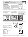
Fig. 1 Thermostat 501x.
2. MOUNTING / INSTALLATION
Open the thermostat cover and dismount
the internal cover with a screwdriver. Use
the enclosed screws to mount the thermo
-
stat on the wall (See Fig 2a).
The thermostat should not be placed on an
outer wall or near any heating sources, e.g.
television, stereo, fireplace etc.
Do not place the thermostat so it can be
exposed to direct sunlight. A suitable place
-
Terminal L
→ Phase 24V
Terminal N
→ Neutral 24V
Terminal
→ Switched phase
Terminal
→ Terminal for time control
Terminal TR
→ Thermal feedback
(activated when TR and
N
are connected)
Fig. 2a Fig. 2b
TR
TR
N
L
�
��
�
TA
Fig. 2c
1. OVERVIEW / FUNCTION
This manual describes the function and
installation of the Thermostat 501x (see
Fig. 1) which is part of the heating control
system. The system consists of the following
components: Wiring Center 375x, Thermo
-
stat 501x (or Thermostat 506x) and Mixing
Control 355x.
The system is approved for use in the EU
and EFTA countries.
– Data Brochure
Thermostat 501x, one stage heat
D 501x
05.09
UK
The thermostat measures the temperature
and compares it with the setting value. (The
setting value is set with the turning knob).
If the measured value is below the set value
the thermostat demands heat.
When the
desired temperature has been reached, the
thermostat terminates the heat
demand to
the wiring center.
ment is close to where you stay and approx.
1,5 m. above the floor. (See Fig. 2b).
In very damp and steamy rooms, the ther
-
mostat should be placed as far away as
possible from source of moisture.
Connect the terminals of the thermostat to
the corresponding terminals in the wiring
center. See separate manual for the Wiring
Center 375x.
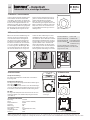
3. SETTINGS
Temperature setting:
The desired temperature is set by the turning knob on
the front.
Time controlled setback:
Time controlled setback can be selected with the slide
switch in
position. This is only possible if the wiring
center is connected to the Mixing Control 355x which
includes a setback timer.
Min/max:
The set temperature can be limited mechanically with the
blue and red pins underneath the turning knob (See Fig. 3)
Fig. 3 Temperature settings.
5. TECHNICAL DATA
Voltage: 24V AC
Current: 0,5A (2A max. 120 sec.)
Temperature range: 6-30˚C
Hysteresis: 0,5 K
Marking: CE
Scale precision: 2 K
Setback: 4 K drop (20°C to 16°C)
Ambient humidity: <90%
Housing: IP20
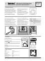
Fig. 4 Dimensions of the thermostat.
4. DIMENSIONS
10
20
30
kanmor Control Systems Ltd. Head Office: 5100 Silver Star Road · Vernon, B.C. Canada V1B 3K4 · Tel. +1-250-545-2693 · Fax. +1-250-549-4349 · www.kanmor.com
European Office: Unit 6, Cartwright Court, Cartwright Way, Bardon Hill, Coalville, Leicestershire, LE67 1UE, ENGLAND Tel. +44(0)1530 519666 Fax: +44(0)1530 519667

30
20
10
Abb. 1 Thermostat 501x.
2. MONTAGE / INSTALLATION
Öffnen Sie die Thermostatabdeckung und
entfernen Sie die innere Abdeckung mit
einem Schraubendreher. Befestigen Sie
den Thermostaten mit den mitgelieferten
Schrauben an der Wand (siehe Abb. 2a).
Der Thermostat darf weder an Außenmau
-
ern noch in der Nähe von Wärmequellen,
z. B. Fernsehgeräten, Musikanlagen, Öfen
usw. angebracht werden. Der Thermostat
darf nicht der direkten Sonne ausgesetzt
Anschlussklemme L → Phase 24V
Anschlussklemme N → Nullleiter 24V
Anschlussklemme → Geschaltete Phase
Anschlussklemme → Anschlussklemme
für Zeitsteuerung
Anschlussklemme TR → Thermische
Rückmeldung
(aktiviert wenn TR und N
angeschlossen sind)
Abb. 2a Abb. 2b
TR
TR
N
L
�
��
�
TA
Abb. 2c
1. ÜBERBLICK / FUNKTIONSWEISE
In dieser Anleitung wird die Funktionsweise
und Installation des Thermostaten 501x
(siehe Abb. 1) beschrieben; der Thermostat
ist Teil des Wärmeregelsystems. Das System
besteht aus den folgenden Bauteilen: Ver
-
drahtungscenter 375x, Thermostat 501x (oder
Thermostat 506x) und Mischerregelung 355x.
Das System ist für die Verwendung in den
EU- und EFTA-Ländern zugelassen. Der
– Datenblatt
Thermostat 501x, einstufige Heizphase
D 501x
05.09
DE
Thermostat misst die Temperatur und ver-
gleicht sie mit dem Sollwert. (Der Sollwert
wird mit dem Drehknopf eingestellt).
Wenn die gemessene Temperatur unter
dem Sollwert liegt, benötigt der Thermostat
Zufuhr von Wärme. Sobald die gewünschte
Temperatur erreicht ist, beendet der Ther
-
mostat die Wärmeanforderung an das Ver
-
drahtungscenter.
werden. Die beste Platzierung ist in Ihrer
unmittelbaren Nähe und etwa 1,5 m über
dem Fußboden. (Siehe Abb. 2b). In Räumen
mit Feuchtigkeit und Dampf muss der Ther
-
mostat möglichst weit von der Feuchtigkeit
-
squelle installiert werden. Schließen Sie
die Anschlussklemmen des Thermostaten
an die entsprechenden Anschlussklemmen
im Verdrahtungscenter an. Siehe separate
Anleitung für das Verdrahtungscenter 375x.
3. EINSTELLUNGEN
Temperatureinstellung:
Die gewünschte Temperatur wird mit dem vorderen Dreh
-
knopf eingestellt.
Zeitgesteuerte Absenkung:
Die zeitgesteuerte Absenkung wird mit dem Schieberegler in
der Position
gewählt.
Diese Möglichkeit besteht nur dann, wenn das Verdrahtungs
-
center an die Mischerregelung 355x angeschlossen ist; diese
Konstellation schließt eine Schaltuhr zur Absenkung mit ein.
Min./Max.
Die eingestellte Temperatur kann mechanisch mi
t den roten
und blauen Nadeln unter dem Drehknopf begrenzt werden
(siehe Abb. 3)
Abb. 3 Temperatur-
einstellungen.
5. TECHNISCHE DATEN
Spannung: 24 V AC
Strom: 0,5 A (2 A max. 120 Sek.)
Temperaturbereich: 6-30˚C
Hysterese: 0,5 K
Markierung: CE
Genauigkeit der Skala: 2 K
Absenkung: 4 K Abfall (20°C to 16°C)
Umgebungsfeuchte: <90%
Gehäuse: IP20
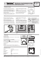
Abb. 4 Abmessungen des Thermostaten.
4. ABMESSUNGEN
10
20
30
kanmor Control Systems Ltd. Hauptstelle: 5100 Silver Star Road · Vernon, B.C. Canada V1B 3K4 · Tel. +1-250-545-2693 · Fax. +1-250-549-4349 · www.kanmor.com
Niederlassung in Europa: Unit 6, Cartwright Court, Cartwright Way, Bardon Hill, Coalville, Leicestershire, LE67 1UE, ENGLAND Tel. +44(0)1530 519666 Fax: +44(0)1530 519667

30
20
10
Rys. 1 Termostat 501x.
2. MONTAŻ / INSTALACJA
Otworzyć pokrywę termostatu i
zdemontować pokrywę wewnętrzną za
pomocą śrubokręta. Wykorzystać dołączone
wkręty do zamontowania termostatu na
ścianie (patrz Rys. 2a).
Nie należy umieszczać termostatu na ścianie
szczytowej ani w pobliżu jakichkolwiek
źródeł ciepła, np. telewizora, wieży stereo,
kominka, itp. Nie należy umieszczać ter
-
mostatu w miejscu narażonym na działanie
Zacisk L → Faza 24V
Zacisk N → Zero 24V
Zacisk → Zamieniona faza
Zacisk → Zacisk sterowania czasowego
Zacisk TR → Cieplne sprzężenie zwrotne
(załączane po podłączeniu
TR i N)
Rys. 2a Rys. 2b
TR
TR
N
L
�
��
�
TA
Rys. 2c
1. PRZEGLĄD / DZIAŁANIE
Niniejsza instrukcja opisuje działanie i
instalację termostatu 501x (patrz Rys. 1),
który stanowi element systemu sterowania
ogrzewaniem. W skład systemu wchodzą
następujące komponenty: szafka kablowa
375x, termostat 501x (lub termostat 506x) i
sterowanie mieszaniem 355x.
System został dopuszczony do użytku
w krajach UE i EFTA. Termostat mierzy
– Broszura informacyjna
Thermostat 501x, ogrzewanie jednostopniowe
D 501x
05.09
PL
temperaturę i porównuje ją z wartością
zadaną. (Wartość zadaną ustawia się za
pomocą pokrętła).
Jeśli zmierzona wartość jest niższa od
wartości zadanej, termostat zgłasza
zapotrzebowanie na ciepło. Po osiągnięciu
żądanej temperatury, termostat przesyła
informację o braku zapotrzebowania na
ciepło do szafki kablowej.
promieni słonecznych. Odpowiednim
miejscem jest to, w którym zwykle znajduje
się użytkownik, na wysokości ok. 1,5 m nad
podłogą. (Patrz Rys. 2b).
W pomieszczeniach bardzo wilgotnych
i zaparowanych, termostat należy umieścić
jak najdalej od źródeł wilgoci. Zaciski ter
-
mostatu należy podłączyć do odpowiednich
zacisków w szafce kablowej. Patrz odd
-
zielna instrukcja szafki kablowej 375x.
3. USTAWIENIA
Ustawienie temperatury:
Żądaną temperaturę ustawia się za pomocą przedniego pokrętła.
Programowanie czasowe:
Programowanie czasowe można wybrać, ustawiając suwak
w położeniu
.
Jest to możliwe dopiero po podłączeniu szafki kablowej do
sterowania mieszaniem 355x z programatorem czasowym.
Min./Maks.:
Zadaną temperaturę można ograniczyć mechanicznie za
pomocą niebieskich i czerwonych bolców pod pokrętłem
(patrz Rys. 3)
Rys. 3 Ustawienia temperatury.
5. DANE TECHNICZNE
Napięcie: 24 V AC
Prąd: 0,5 A (2 A maks. 120 s)
Zakres temperatur: 6-30˚C
Histereza: 0,5 K
Oznaczenie: CE
Dokładność skali: 2 K
Programowanie czasowe: Spadek 4 K (20°C do 16°C)
Wilgotność otoczenia: <90%
Stopień ochrony: IP20
Rys. 4 Wymiary termostatu.
4. WYMIARY
10
20
30
kanmor Control Systems Ltd. Centrala: 5100 Silver Star Road · Vernon, B.C. Canada V1B 3K4 · Tel. +1-250-545-2693 · Fax. +1-250-549-4349 · www.kanmor.com
Biuro europejskie: Unit 6, Cartwright Court, Cartwright Way, Bardon Hill, Coalville, Leicestershire, LE67 1UE, ENGLAND Tel. +44(0)1530 519666 Fax: +44(0)1530 519667

30
20
10
Obr. 1 Thermostat 501x.
2. MONTÁŽ / INSTALACE
Otevřete víko termostatu a pomocí
šroubováku odmontujte vnitřní kryt. K
připevnění termostatu na stěnu použijte
přiložené šrouby (viz obr. 2a).
Termostat by neměl být umístěn na vnější
stěně nebo v blízkosti zdrojů tepla, např.
televizoru, stereofonní soustavy, krbu atd.
Umístěte termostat tak, aby nebyl vystaven
přímému slunečnímu svitu. Vhodné umístění
Svorka
L → Fázový vodič 24V
Svorka
N → Nulový vodič 24V
Svorka
→ Spínaná fáze
Svorka
→ Svorka pro časově závislou
regulaci
Svorka TR
→ Teplotní zpětná vazba
(aktivuje se po připojení
svorek TR a N)
Obr. 2a Obr. 2b
TR
TR
N
L
�
��
�
TA
Obr. 2c
1. PŘEHLED / FUNKCE
Tato příručka popisuje funkci a instalaci
zařízení Thermostat 501x (viz obr. 1), které
je součástí systému regulace vytápění.
Systém sestává z následujících komponent:
Wiring Center 375x, Thermostat 501x (nebo
Thermostat 506x) a směšovací zařízení
Mixing Control 355x.
Systém je schválen pro používání v zemích
EU a ESVO. Termostat měří teplotu a por
-
– Brožura s technickými údaji
Thermostat 501x, jednostupňový ohřev
D 501x
05.09
CZ
ovnává ji s nastavenou hodnotou. (Nasta-
vená hodnota se zadává pomocí otočného
knoflíku).
Je-li naměřená hodnota nižší než nasta-
vená hodnota, vysílá termostat požadavek
ohřevu. Po dosažení požadované teploty
zruší termostat požadavek ohřevu
předávaný spínacímu rozvaděči.
je v blízkosti místa, ve kterém se nejvíce
zdržujete, a přibližně 1,5 m nad podlahou.
(Viz Obr. 2b).
Ve velmi vlhkých místnostech s vysokým
obsahem páry v ovzduší by měl být termostat
umístěn co nejdále od zdroje vlhkosti. Připojte
svorky termostatu k odpovídajícím svorkám ve
spínacím rozvaděči. Viz samostatná příručka
ke spínacímu rozvaděči Wiring Center 375x.
3. NASTAVENÍ
Nastavení teploty:
Požadovaná teplota se nastavuje pomocí otočného knoflíku na
přední straně přístroje.
Časově závislá regulace se zpožděním:
Regulované zpoždění je možno nastavovat pomocí posuvného
přepínače v poloze
.
Toto je možné pouze tehdy, je-li spínací rozvaděč připojen
ke směšovači Mixing Control 355x, který obsahuje časovač s
funkcí zpoždění.
Min/max:
Nastavenou teplotu je možno mechanicky omezit pomocí
modrého a červeného kolíku pod otočným knoflíkem (viz
obr. 3)
Obr. 3 Nastavení teploty
5. TECHNICKÉ ÚDAJE
Napětí: 24V střídavé
Proud: 0,5A (2A max. po dobu 120 s)
Rozsah teploty: 6-30˚C
Hystereze: 0,5 K
Označení: CE
Přesnost stupnice: 2 K
Zpoždění: Pokles o 4 K (20°C až 16°C)
Okolní vlhkost: <90%
Pouzdro: IP20
Obr. 4 Rozměry termostatu.
4. ROZMĚRY
10
20
30
kanmor Control Systems Ltd. Ústředí: 5100 Silver Star Road · Vernon, B.C. Canada V1B 3K4 · Tel. +1-250-545-2693 · Fax. +1-250-549-4349 · www.kanmor.com
Evropská kancelář: Unit 6, Cartwright Court, Cartwright Way, Bardon Hill, Coalville, Leicestershire, LE67 1UE, ENGLAND Tel. +44(0)1530 519666 Fax: +44(0)1530 519667
088N1966 | 01.03.2005 | Version 00
-
 1
1
-
 2
2
-
 3
3
-
 4
4


w innych językach
- Deutsch: Kanmor 501x
- slovenčina: Kanmor 501x
Inne dokumenty
-
Elektrobock PT02 Instrukcja obsługi
-
OJ Electronics OTN Instrukcja obsługi
-
-
 OJ OTD2-1655 Instrukcja obsługi
-
STIEBEL ELTRON RTU-TC Operation Instruction
-
STIEBEL ELTRON RTF-TC | RTU-TC Operation Instruction
-
-
OJ Electronics OCD4 Instrukcja obsługi
-
-
Tyco TA Operation And Use Manual
