
DELTA-SE • DELTA-SI
R
CAME France S.a.
Nanterre Cedex
-
CAME GmbH
Korntal
-
CAME Automatismes S.a.
Marseille -
CAME GmbH Seefeld
Seefeld
-
CAME Automatismos S.a.
Madrid -
CAME Gulf Fze
Dubai
-
CAME United Kingdom Ltd.
Nottingham
CAME Rus
Moscow
-
CAME Group Benelux S.a.
Lessines -
CAME (Shanghai) Automatic Gates Co. Ltd
Shanghai
-
CAME Americas Automation Llc
Medley
-
CAME Portugal
Porto
CAME Cancelli Automatici S.p.a.
Dosson Di Casier
-
CAME Sud s.r.l.
Napoli
-
CAME Service Italia S.r.l.
Dosson di Casier
-
Nederlands
NED
Español
ESP
Deutch
DEU
Français
FRA
Русский
RUS
English
ENG
Polski
POL
Italiano
ITA
Português
PRT
FOTOCELLULE - PHOTOCELLS - PHOTOCELLULES
PHOTOZELLEN -PHOTOZELLEN -FOTOCELULAS
FOTOCÉLULAS - FOTOKOMÓRKI -
ФОТОЭЛЕМЕНТЫ
SERIE - SERIES - SÉRIE
BAUREIHE - SERIE - SERIE
SÉRIE - SERIA -
СЕРИЯ

I dati e le informazioni indicate in questo manuale sono da ritenersi suscettibili di modifica in qualsiasi momento e senza obbligo di preavviso da parte di CAME cancelli automatici s.p.a.
Pag.
2
- Codice manuale:
119RV19
119R V19 ver.
1.0
1.0 02/2010 © CAME cancelli automatici s.p.a.
ITA
ITA
“ISTRUZIONI IMPORTANTI PER LA SICUREZZA DURANTE
L’INSTALLAZIONE”
ATTENZIONE: L’INSTALLAZIONE NON CORRETTA PUÒ CAUSARE
GRAVI DANNI SEGUIRE TUTTE LE ISTRUZIONI DI INSTALLAZIONE
IL PRESENTE MANUALE È DESTINATO SOLAMENTE A
INSTALLATORI PROFESSIONALI O A PERSONE COMPETENTI.
Dati tecnici
Lunghenza d’onda infrarosso: 880 nm
Portata: 20 m
Alimentazione: 12/24V AC/DC
Portata contatti relè: 500 mA max a 24V
Assorbimento: 70 mA - 24V AC
Grado di protezione: IP54
Classe d’isolamento: III
Temperatura di esercizio: -20° ÷ 55°
Materiale: nylon caricato vetro
Descrizione prodotto
Coppia di fotocellule a raggio infrarosso con portata fi no a
20 m garantiti in qualsiasi condizione atmosferica. Compa-
tibile con la serie DIR.
DELTA SE = Con corpo e circuiti alloggiati in un contenitore tutto
esterno alla colonna di fi ssaggio. Ingombro 70x70x36 mm.
DELTA SI = Con corpo e circuiti alloggiati in un contenitore
da murare, inserire in pilastri di metallo oppure su colonnine
di supporto DIR-L. Ingombro 70x70x16 mm.
Composizione articoli
- Base contenitore DELTA-SE
- Contenitore DOC-S per DELTA-SI
- Base contenitore DELTA-SI
- Frontalino contenitore DELTA
- Scheda circuiti elettronici TX/RX
- Viti fi ssaggio scheda DELTA-SE
- Viti*+OR fi ssaggio base
- Vite fi ssaggio frontalino
- Filettatura per maschio di pressacavo tipo PG7, integrata
sulla base contenitore
* DELTA-SE: viti non fornite; da scegliere secondo il tipo di
fi ssaggio (max ø 4 mm).
Dismissione e smaltimento
- I componenti dell’imballo (cartone, plastiche etc.) sono assimilabili
ai rifi uti solidi urbani e possono essere smaltiti senza alcuna diffi coltà,
semplicemente effettuando la raccolta differenziata per il riciclaggio.
Prima di procedere è sempre opportuno verifi care le normative specifi che
vigenti nel luogo d’installazione.
Altri componenti (schede elettroniche, batterie dei radiocomandi etc.)
possono invece contenere sostanze inquinanti. Vanno quindi rimossi
e consegnati a ditte autorizzate al recupero e allo smaltimento degli
stessi.
NON DISPERDERE NELL’AMBIENTE!
CAME Cancelli Automatici S.p.A. dichiara
sotto la propria responsabilità, che i seguenti
prodotti per l’automazione di cancelli e porte
da garage, cosi denominati:
DELTA-SI / DELTA-SE
Sono conformi ai requisiti essenziali ed alle
disposizioni pertinenti, stabilite dalle seguenti
Direttive e alle parti applicabili delle Normative
di riferimento in seguito elencate:
2004/108/CE Direttiva Compatibilità
Elettromagnetica
2006/95/CE Direttiva Bassa Tensione
Normative EN 61000-6-2, EN 61000-6-3, EN
13241-1, EN 60335-1, EN 60335-2-103.
AVVERTENZA IMPORTANTE!
È vietato mettere in servizio il/i prodotto/i,
oggetto della presente dichiarazione, prima
del completamento e/o incorporamento,
in totale conformità alle disposizioni della
Direttiva Bassa Tensione 73/23/CEE
L’
Amministratore Delegato
Sig. Gianni Michielan
DICHIARAZIONE DI CONFORMITÀ
Ai sensi della Direttiva sulla Compatibilità Elettromagnetica
Dichiarazione del fabbricante
Installazione
Prima di procedere all’installazione è necessario:
• Assicurarsi che la tensione di linea sia scollegata.
• Verifi care che il punto di fi ssaggio dell’apparecchiatura sia
in una zona protetta dagli urti, che le superfi ci di ancoraggio
siano solide, e che il fi ssaggio venga fatto con elementi idonei
(viti, tasselli, ecc) alla superfi cie.
• Predisporre tubazioni e canaline adeguate per il passaggio
dei cavi elettrici.
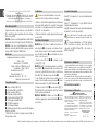
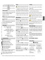
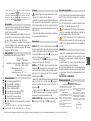
Descrizione di montaggio
DELTA SE fi gura - Forare dalla parte posteriore le
basi contenitore per far passare cavi e idonee viti scelte
in base al tipo di pilastro; fi ssare quindi le basi (usando
anche gli OR in dotazione ), posizionandole alla stessa
altezza e sullo stesso asse;
- Fissare le schede TX e RX e collegarle come da
schemi , , o ;
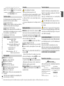
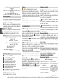
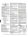
DELTA SI fi gura - Su muratura predisporre i contenitori a
incasso DOC-S posizionandoli alla stessa altezza e sullo
stesso asse. Su pilastri in ferro invece, forare con una fresa a
tazza ø60 per introdurre le basi contenitore .
- Forare dalla parte posteriore le basi contenitore per far
passare i cavi (è consigliato usare un pressacavo ); fi ssare
quindi le basi usando le viti e gli OR in dotazione ;
- Collegare le schede TX e RX come da schemi , , o
e quindi inserirle a scatto sulle basi contenitore, facendole
scorrere nelle apposite guide ;
DELTA SE / DELTA SI - Chiudere con la vite le basi
contenitore, agganciando e ruotando il frontalino dall’alto
verso il basso.
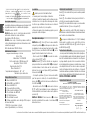
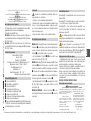
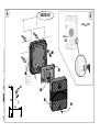
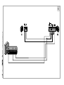
Schemi di collegamento
Figura - Collegamento di 1 coppia in riapertura durante
la chiusura.
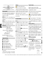
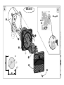
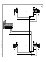
Figura - Collegamento di 2 coppie (DELTA S+DIR) in
riapertura durante la chiusura.
Figura - Collegamento di 2 coppie: una in riapertura durante
la chiusura e una in stop parziale .
Per i contatti di uscita C-NC, verifi care sempre le indicazioni
collegamento/funzione nel manuale del quadro di comando Came
associato.
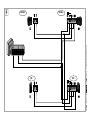
Per passare all’alimentazione a 12V (24V standard),
occorre ponticellare le piazzole sulle schede RX, lato
componenti su DELTA-SE (fi gura ) o lato opposto su
DELTA-SI (fi gura ).

ENG
ENG
The data and information reported in this installation manual are susceptible to change at any time and without obligation on CAME cancelli automatici s.p.a. to notify users.
Pag.
3
- Manual code:
119RV19
119R V19 ver.
1.0
1.0 02/2010 © CAME cancelli automatici s.p.a.
Technical features
Infrared wavelength: 880 nm
Range: 20 m
Power supply: 12/24V AC/DC
Relay contact rating: 500 mA max a 24V
Power draw: 70 mA - 24V AC
Protection rating: IP54
Insulation class: III
Working temperatures: -20° ÷ 55°
Material: nylon caricato vetro
Product description
Pair of infrared-beam photocells with range of up to 20 m –
guaranteed to work in any weather conditions.
Compatible with the DIR series.
DELTA SE = Features body and circuitry housed within a
container that is fully external to the anchoring post.
Overall dimensions 70 x 70 x 36 mm.
DELTA SI = Features body and circuitry housed within a con-
tainer fi tted into the wall requiring masonry work, or inserted
into metal pillars or on support DIR-L posts.
Overall dimensions 70 x 70 x 16 mm.
Item composition
- DELTA -SE container base
- DOC-S container for DELTA-SI
- DELTA-SI container base
- Delta series front-piece
- TX/RX electronic circuit board
- DELTA-SE electronic board securing screws
- Screws*+OR base anchoring
- Front-piece securing screw
-Threading for PG7-type male cable gland, added to the
casing base
* DELTA-SE: screws not supplied; to choose depending on the
type of anchoring (ø = 4 mm max).
Installation
Before installing, do the following:
• Make sure that the main current is cut off.
• Check that the spot where the equipment will be secured
is protected from possible impacts, and that the surfaces
are sturdy, and that the screws and wall plugs used are
suitable for the job.
• Set up proper tubing and ducts to run through electrical
cable.
Mounting instructions
DELTA-SE fi gure - Perforate the container bases
from the back so that cables and suitable bolts depending on
the chosen type of support posts can pass through; secure
and then the bases (also using the supplied Ors), position
at the same height and on the same plane;
- Secure the TX and boards and connect them as
shown in the diagrams , , o ;
DELTA-SI fi gure - On masonry wall set up the DOC-S
sink-in containers, positioning them at the same height
and plane.
While, on metal posts, perforate with a hollow ø 60 per
casing bases .
- Perforate from the back, the container bases to allow
cables to pass through (use a cable gland ), then secure
the bases using supplied screws and ORs ;
- Connect the TX and RX boards as shown in the , ,
o diagrams and then snap in onto the container bases,
sliding them along their apposite rails ;
DELTA-SE / DELTA-SI - Close the container base using the
screw hooking in and turning the front piece from top
towards the bottom.
Connection diagrams
Figure – Connecting one opening pair during closing.
Figure – Connecting two reopening pairs (of the Delta S
+ Dir series) during closing.
Figure – Connecting two pairs: one reopening during
closing and one in partial stop .
For the C-NC output contacts, always check the con-
nection/functioning instructions in the relative Came control
panel manual.
To shift to the 12 V power mode (24 V being the stan-
dard), you need to bridge the bonding pads on the RX boards,
components side on DELTA-SE (fi gure ) or on the opposite
side on DELTA-SI (fi gure ).
Decomissioning and disposal
The packaging components are made of different materials,
most of which (paper, plastic, etc.) are fi t for solid urban waste
disposal and recycling.
Always check pertinent local legislation before acting.
While, other components such as control boards and transmitter
batteries and so on, and any other hazardous materials must
be removed and handed to specialised waste disposal fi rms
DO NOT DISPOSE OF IN THE ENVIRONMENT!
CAME Cancelli Automatici S.p.A. hereby
declares under its own liability, that the
following gate and garage door automation
products, called:
DELTA-SI / DELTA-SE
Comply with the essential prerequisites
and applicable provisions, set forth by the
following Directives and applicable parts of
the reference Standards:
2004/108/CE Electromagnetic Compatibility
Directive
2006/95/CE Low Voltage Directive
Standards EN 61000-6-2, EN 61000-6-3,
EN 13241-1, EN 60335-1, EN 60335-2-103.
IMPORTANT WARNING!
It is prohibited to employ the product/s in this
statement, before completely complying with
or incorporating the Low Voltage Directive
73/23/CEF.
The Managing Director
Mr Gianni Michielan
STAMENT OF COMPLIANCE
Pursuant to Electromagnetic Compatibility Directive.
Manufacturer’s declaration
“IMPORTANT INSTALLATION SAFETY INSTRUCTIONS”
WARNING: IMPROPER INSTALLATION MAY RESULT IN SERIOUS
DAMAGE. FOLLOW ALL INSTRUCTIONS IN THIS INSTALLATION
MANUAL.
THIS MANUAL IS INTENDED ONLY FOR PROFESSIONAL INSTALLERS
AND OTHER COMPETENT PERSONS.

FRA
FRA
Les données et les indications fournies dans ce manuel d’installation peuvent subir des modifications à tout moment sans avis préalable de la part de CAME cancelli automatici s.p.a.
Pag.
4
- Code manuel:
119RV19
119R V19 ver.
1.0
1.0 02/2010 © CAME cancelli automatici s.p.a.
Informations techniques
Longueur d’onde infrarouge : 880 nm
Portée: 20 m
Alimentation: 12/24V AC/DC
Portée contact relais : 500 mA max a 24V
Absorption: 70 mA - 24V AC
Degré de protection: IP54
Classe d’isolation : III
Température de fonctionnement : -20° ÷ 55°
Materiale: nylon caricato vetro
Description du produit
Jeu de photocellules à rayon infrarouge avec portée jusqu’à 20
m, garantis dans toutes les conditions atmosphériques.
Compatible avec la série DIR .
DELTA SE = Avec corps et circuits logés dans un boîtier
entièrement extérieur à la colonne de fi xation.
Encombrement 70 x 70 x 36 mm.
DELTA SI = Avec corps et circuits logés dans un boîtier à
sceller, à introduire dans des piliers en métal ou bien sur des
colonnettes de support
DIR-L. Encombrement 70x 70 x 16 mm.
Composition des articles
- Base boîtier DELTA-SE
- Boîtier DOC-S pour DELTA-SI
- Base boîtier DELTA-SI
- Face avant boîtier série Delta
- Carte circuits électroniques TX/RX
- Vis de fi xation carte DELTA-SE
- Vis*+OR fi xation base
- Vis de fi xation face avant
- Filetage pour mâle de serre-câble type PG7, incorporé
sur la base du boîtier.
* DELTA-SE: vis non fournies ; à choisir
selon le type de fi xation (ø = 4 mm max).
Installation
Avant de procéder à l’installation il faut :
• S’assurer que la tension de ligne est branchée.
• Vérifi er si l’endroit où l’appareil sera fi xé est dans une zone
à l’abri des chocs, si les superfi cies d’ancrage sont solides,
et veiller à ce que la fi xation soit exécutée avec les éléments
appropriés (vis, chevilles, etc.) à la superfi cie.
• Préparer des gaines et des moulures appropriées pour le
passage des câbles électriques.
Description du montage
DELTA-SE dessin - Percez Percez les bases du boîtier
sur la partie postérieure pour faire passer les câbles et les
vis adéquates choisies par rapport au type de pilier ; ensuite
fi xez les bases (en utilisant les OR fournis ), en les
plaçant à la même hauteur et sur le même axe ;
- Fixez les cartes TX et RX et raccordez-les comme
sur les schémas , , ou ;
DELTA-SI dessin - Sur des éléments en maçonnerie
prévoyez les boîtiers à encastrement DOC-S en les plaçant
à la même hauteur et sur le même axe. Par contre sur des
piliers en fer percez avec un trépan ø 60 pour introduire
les bases du boîtier .
- Sur la partie postérieure percez les bases du boîtier
pour faire passer les câbles (il est conseillé d’utiliser un
presse-câble ); ensuite fixez les bases en utilisant les vis
et les OR fournis ;
- Raccordez les cartes TX et RX comme sur les schémas
, , ou et puis introduisez-les par encliquetage sur
les bases du boîtier, en les faisant coulisser sur les glissières
spéciales ;
DELTA-SE / DELTA-SI - Fermez avec la vis les bases
du boîtier, en attachant la face avant et en la tournant
du haut vers le bas.
Schémas de raccordement
Dessin – Raccordement d’un jeu en réouverture pendant
la fermeture.
Dessin – Raccordement de deux jeux (série Delta S +
série Dir) en réouverture pendant la fermeture.
Dessin – Raccordement de deux jeux : un en réouverture
pendant la fermeture et un en stop partiel .
Pour les contacts de sortie C-NC, vérifi ez toujours les
indications raccordement/fonctionnement sur le manuel fourni
avec l’armoire de commande Came.
Pour passer à l’alimentation en 12 V (24 V standard),
il faut ponter les pastilles sur les cartes RX, du côté des
composants sur DELTA-SE (dessin ) ou du côté opposé
sur DELTA-SI (dessin ).
Destruction et élimination
- Les composants de l’emballage (carton, matières plastiques,
etc.) sont assimilables aux déchets solides urbains, ils peuvent
donc être facilement éliminés en faisant le tri sélectif pour le
recyclage. Avant de procéder, il est nécessaire de s’informer
sur la réglementation en vigueur en la matière dans le pays
où le dispositif est monté. Par contre les autres composants
(cartes électroniques, batteries des émetteurs, etc.) peuvent
contenir des substances polluantes. Il faut donc les confi er aux
sociétés chargées du traitement et de l’élimination des déchets.
NE PAS JETER DANS LA NATURE
CAME Cancelli Automatici S.p.A. déclare
sous sa responsabilité que les produits
suivants pour l’automatisme de portails et de
portes de garage, dénommés :
DELTA-SI / DELTA-SE
Sont conformes aux conditions requises
indispensables et aux dispositions indiquées,
fi xées par les Directives suivantes et aux
parties applicables des Réglementations de
référence précisées ci-après.
2004/108/CE Directive Compatibilité
Electromagnétique
2006/95/CE Directive Basse Tension
Réglementations EN 61000-6-2, EN 61000-
6-3, EN 13241-1, EN 60335-1, EN 60335-
2-103.
AVERTISSEMENT IMPORTANT
Il est interdit de mettre en service
le/s produit/s, objet de la déclaration
présente, avant son achèvement et/ou son
incorporation, dans le respect total des
dispositions de la Directive Basse Tension
73/23/CEEL’
L’administrateur Délégué
Monsieur Gianni Michielan
DECLARATION DE CONFORMITE
Aux termes de la Directive sur la Compatibilité Electromagnétique
Déclaration du fabricant
’’REGLES DE SECURITE IMPORTANTES POUR L’INSTALLATION’’
ATTENTION : L’INSTALLATION INCORRECTE PEUT S’AVERER
DANGEREUSE, SUIVEZ TOUTES LES INSTRUCTIONS
D’INSTALLATION
CE MANUEL EST DESTINE EXCLUSIVEMENT A DES INSTALLATEURS
PROFESSIONNELS OU A DES PERSONNES EXPERIMENTEES

DEU
DEU
Seite
5
- Handbuch-Code:
119RV19
119R V19 ver.
1.0
1.0 02/2010
© CAME cancelli automatici s.p.a.
Sämtliche in der Installationsanleitung aufgeführten Daten und Informationen können jederzeit und ohne Vorankündigung von CAME cancelli automatici s.p.a verändert werden.
Technische Daten
Länge des Infrarotstrahls: 880 nm
Reichweite: 20 m
Stromversorgung: 12/24V AC/DC
Strombelastbarkeit Relais: 500 mA max bei 24V
Absorption: 70 mA - 24V AC
Schutzart: IP54
Isolierklasse: III
Betriebstemperatur: -20° ÷ 55°
Material: Nylon-Glasfi ber
Produktbeschreibung
Paar Infrarot-Lichtschranken mit einer Reichweite bis zu 20
m, garantiert in allen Witterungsverhältnissen.
Kompatibel mit der Serie DIR.
DELTA-SE = Schaltkreise und Lichtschrankenkörper befi nden
sich in einem extern auf der Standsäule montiertem Gehäuse.
Maße 70 x 70 x 36 mm.
DELTA-SI = Schaltkreise und Lichtschrankenkörper befi nden
sich in einem einzumauernden bzw. in die Torpfosten oder
Standsäulen zu integrierendem Gehäuse DIR.
Maße 70 x 70 x 16 mm.
Bestandteile der Artikel
- Grundplatte für DELTA-SE-Gehäuse
- Gehäuse DOC-S für DELTA-SI
- Grundplatte für DELTA-SI-Gehäuse
- Frontplatte für Gehäuse der Serie Delta
- Platine mit elektronischem Schaltkreis TX/RX
- Schrauben für Platine DELTA-SE
- Schrauben*+OR für Grundplatte
- Schraube für Frontplatte
- Gewinde für Steckverbindung mit Außengewinde Typ
PG7, in die Grundplatte des Gehäuses integriert.
*DELTA-SE: Schrauben nicht inbegriffen, werden je nach
Befestigungsart ausgewählt (ø = max. 4 mm).
Montage
Vor der Montage sind folgende Kontrollen vorzunehmen:
• Überprüfen, dass die Stromzufuhr unterbrochen wurde.
• Überprüfen, dass die Anlage an einem vor Stößen ge-
schützten Standort montiert werden, dass die zur Verankerung
verwendeten Flächen solide sind und dass die Anlage mit
geeignetem Material (Schrauben, Dübel usw.) verankert wird.
• Geeignete Kabelrohre und –schläuche vorsehen.
Montage-Anleitung
DELTA-SE Abb - Forare Grundplatten der Gehäuse von
hinten durchbohren, damit Kabel und für den Pfostentyp
geeignete Schrauben durch die Löcher gehen; fi ssare
daraufhin die Grundplatten befestigen (dazu auch die mit-
gelieferten OR verwenden ), diese in derselben Höhe und
auf derselben Achse positionieren;
- Die TX- und RX-Platinen befestigen und diese, wie in
den Schaltplänen , , oder angegeben, befestigen;
DELTA-SI Abb - Bei Pfeilern aus Mauerwerk die Einbauge-
häuse DOC-S in derselben Höhe und auf derselben Achse
positionieren. Bei Eisenpfeilern mit einem Fräser ø 60 ein
Loch für die Gehäuse-Grundplatten bohren .
- Grundplatten der Gehäuse von hinten durchbohren,
um die Kabel hindurchzuführen (es wird empfohlen eine
Steckverbindung zu verwenden ); daraufhin die Grundplatten
befestigen dazu auch die mitgelieferten Schrauben und OR
verwenden ;
- Die TX- und RX-Platinen wie in den Schaltplänen ,
, oder angegeben, befestigen und anschließend mittels
der dafür vorgesehenen Schienen auf den Gehäuse-
Grundplatten einrasten;;
DELTA-SE / DELTA-SI - Mit der Schraube die Gehäuse-
Grundplatten schließen und dabei die Frontplatte von oben
nach unten einrasten und drehen.
Schaltpläne
Abb. – Anschluss von einem Paar Lichtschr. für Wiede-
raufl auf bei Zulauf.
Abb. – Anschluss von zwei Paar Lichtschr. (Serie Delta S
+ Serie Dir) für den Wiederaufl auf bei Zulauf.
Abb. – Anschluss von zwei Paar Lichtschr: ein Paar für den
Wiederaufl auf bei Zulauf und eine für den Teilstopp .
Bei Ausgangskontakten C-NC immer die Anschluss/
Funktions-Angaben im Anleitungsheft der entsprechenden
Steuerung von Came überprüfen.
Um auf 12 V umzustellen (24 V = standard) müssen die
pad. auf den RX-Platinen überbrückt werden, Seite mit den
Komponenten bei DELTA-SE (Abb. ) oder Gegenseite bei
DELTA-SI (Abb. ).
Abbruch und Entsorgung
- Die Bestandteile der Verpackung (Pappe, Kunststoff usw.)
können getrennt gesammelt mit dem normalen Hausmüll
entsorgt werden. Vor der Entsorgung, ist es empfehlenswert
sich über die am Installationsort geltenden Vorschriften zu
informieren.
Andere Bestandteile (Platinen, Batterien der Handsender usw.)
können Schadstoffe enthalten. Sie müssen dementsprechend
entfernt und in zugelassenen Fachbetrieben entsorgt oder
recycelt werden.
NICHT IN DER UMWELT ZERSTREUEN
Die Firma CAME Cancelli Automatici S.p.A.
bestätigt unter eigener Verantwortung, dass
folgende Produkte für den automatischen
Antrieb von Toren und Garagentoren:
DELTA-SE / DELTA-SI
den grundlegenden Anforderungen
und entsprechenden Bestimmungen
der folgenden Richtlinien und der
anzuwendenden Teilbestimmungen der im
folgenden aufgeführten Gesetzesvorschriften
entsprechen.
2004/108/EG Richtlinie über
elektromagnetische Verträglichkeit
2006/95/EG Niederspannungsrichtlinie
DIN EN 61000-6-2, EN 61000-6-3, EN
13241-1, EN 60335-1, EN 60335-2-103.
WICHTIGER HINWEIS!
Es ist untersagt, das/die diese Erklärung
betreffende/n Produkt/e vor Fertigstellung
und/oder Einbau gemäß den Bestimmungen
der Niederspannungsrichtlinie 73/23/EWG
zu verwenden.
Geschäftsführer
Herr . Gianni Michielan
KONFORMITÄTSERKLÄRUNG
Gemäß der Niederspannungsrichtlinie
Herstellererklärung
“WICHTIGE SICHERHEITSHINWEISE FÜR DIE MONTAGE”
ACHTUNG: DIE UNSACHGEMÄSSE MONTAGE KANN SCHWERE
SCHÄDEN VERURSACHEN, BITTE DIE MONTAGEANLEITUNG
BEACHTEN.
DIESE ANLEITUNG IST NUR FÜR MONTEURE DOER FACHPERSONAL
GEDACHT.

ESP
ESP
Los datos y las informaciones indicadas en este manual de instalación podrían modificarse en cualquier momento y sin obligación de aviso previo por parte de la firma CAME cancelli automatici s.p.a.
Pag.
6
- Codigo manual:
119RV19
119R V19 ver.
1.0
1.0 02/2010 © CAME cancelli automatici s.p.a.
Datos técnicos
Longitud de onda infrarrojo: 880 nm
Alcance: 20 m
Alimentación: 12/24V AC/DC
Alcance contactos relé: 500 mA max a 24V
Absorción: 70 mA - 24V AC
Grado de protección: IP54
Clase de aislamiento: III
Temperatura de funcionamiento -20° ÷ 55°
Material: nylon + fi bra de vidrio
Descripción producto
Par de fotocélulas de rayo infrarrojo con alcance de hasta 20
m, garantizados para todas las condiciones atmosféricas.
Compatible con la serie DIR.
DELTA-SE = Con cuerpo y circuitos alojados en un contenedor
completamente externo a la columna de fi jación. Dimensiones
máximas 70 x 70 x 36 mm.
DELTA-SI = Con cuerpo y circuitos alojados en un contenedor
a empotrar; introducir en pilares de metal o en columnas de
soporte DIR. Dimensiones máximas 70 x 70 x 16mm.
Composición artículos
- Base contenedor DELTA-SE
- Contenedor DOC-S para DELTA-SI
- Base contenedor DELTA-SI
- Placa frontal contenedor serie Delta
- Tarjeta circuitos electrónicos TX/RX
- Tornillos de fi jación tarjeta DELTA-SE
- Tornillos*+juntas tóricas fi jación base
- Tornillo fi jación placa frontal
- Roscas para lado macho de sujeta-cables tipo PG7,
integradas en la base contenedor.
** DELTA-SE: tornillos no suministrados; a
elegir de acuerdo al tipo de (ø = 4 mm máx).
Instalación
Antes de efectuar la instalación es necesario:
• Cerciorarse que la tensión de línea esté desconectada.
• Verifi car que el punto de fi jación del equipo esté protegido
de choques, que las superfi cies de anclaje sean sólidas y que
la fi jación a la superfi cie sea realizada con elementos idóneos
(tornillos, tacos, etc.).
• Predisponer tuberías y canales adecuados para el pasaje
de los cables eléctricos.
Descripción del montaje
DELTA-SE fi gura - Perforar desde la parte posterior
las bases contenedor para hacer pasar cables y tornillos
elegidos en base al tipo de pilar; fi jar las bases (usando
también las juntas tóricas suministrados ), colocándolas
a la misma altura y en el mismo eje;
- Fijar las tarjetas TX y RX y conectarlas como se indica
en los esquemas , , o ;
DELTA-SI fi gura - Predisponer los contenedores de
empotrado en mampostería DOC-S colocándolos a la
misma altura y en el mismo eje. En cambio, en los pilares
de hierro, perforar con una fresadora de taza ø 60 para
introducir las bases del contenedor .
- Perforar de la parte posterior las bases contenedor para
hacer pasar los cables (se aconseja el uso de un sujeta-cables
); fijar las bases usando los tornillos y las juntas tóricas
suministrados ;
- Conectar las tarjetas TX y RX como se indica en los
esquemas , , o e introducirlas por lo tanto a presión
en la base contenedor, deslizándolas por las relativas guías ;
DELTA-SE / DELTA-SI - Cerrar con el tornillo las bases
contenedor, enganchando y girando la placa frontal desde
arriba hacia abajo.
Esquemas de conexión
Figura -Conexión de un par en reapertura durante el cierre.
Figura - Conexión de dos pares (serie Delta S + serie Dir)
en reapertura durante el cierre.
Figura -Conexión de dos pares: una en reapertura durante
el cierre y una en stop parcial .
Para los contactos de salida C-NC, verifi car siempre
las indicaciones conexión/función en el manual del cuadro
de mando Came adjunto.
Para pasar a la alimentación de 12 V (24 V estándar),
hay que hacer un puente en las plataformas de las tarjetas
RX, lado componentes en DELTA-SE (fi gura B) o lado opuesto
en DELTA-SI (fi gura D).
Desguace y eliminación
- Los componentes del embalaje (cartón, plástico, etc.)
son asimilables a los deshechos sólidos urbanos y pueden
eliminarse sin ninguna difi cultad, efectuando simplemente
la recolección diferenciada para el sucesivo reciclaje de
dichos materiales.
Antes de operar es siempre conveniente verifi car las
normativas específi cas vigentes en el lugar donde se efectuará
la instalación.
Otros componentes (tarjetas electrónicas, baterías de emisores,
etc.) podrían contener sustancias que contaminan. Se deben
quitar de los equipos y entregar a las empresas autorizadas
para la recuperación y la eliminación de los mismos.
¡NO DISEMINAR EN EL MEDIO AMBIENTE!
CAME Cancelli Automatici S.p.A. declara
bajo su responsabilidad que los siguientes
productos para la automatización de puertas
y puertas de garaje, así denominados:
DELTA-SE / DELTA-SI
Cumplen con los requisitos esenciales y con las
disposiciones pertinentes establecidas por las
siguientes directivas y con las partes aplicables
de las normativas de referencia enumeradas
a continuación:
2004/108/CE - Directiva compatibilidad
Electromagnética
2006/95/CE Directiva Baja Tensión
Normativas EN 61000-6-2, EN 61000-6-3,
EN 13241-1, EN 60335-1, EN 60335-2-
103.
¡ADVERTENCIA IMPORTANTE!
Se prohíbe poner en servicio el/los
producto/s, objeto de la presente declaración
antes del completamiento y/o incorporación
sin la conformidad total con las disposiciones
de la Directiva Baja Tensión 73/23/CEE
Director
Sr.
Gianni Michielan
DECLARACIÓN DE CONFORMIDAD
De acuerdo con lo establecido por la Directiva de Compatibilidad Electromagnética
Declaración del fabricante
“IMPORTANTES INSTRUCCIONES DE SEGURIDAD DURANTE
LA INSTALACIÓN”
ATENCIÓN: LA INSTALACIÓN INCORRECTA PODRÍA CAUSAR
DAÑOS GRAVES. RESPETAR TODAS LAS INSTRUCCIONES DE
INTALACIÓN
EL PRESENTE MANUAL ESTÁ DESTINADO SÓLO A
INSTALADORES PROFESIONALES O A PERSONAS COMPETENTES.

NED
NED
Pag.
7
- Handleiding nummer:
119RV19
119R V19 ver.
1.0
1.0 02/2010 © CAME cancelli automatici s.p.a.
De gegevens en informatie in deze handleiding voor de installatie zijn op elk ogenblik vatbaar voor wijziging zonder verplichting tot waarschuwing vooraf door Came Cancelli Automatici S.p.A.
Technische gegevens
Infraroodstraal: 880 nm
Bereik: 20 m
Voeding: 12/24V AC/DC
Vermogen relaiscontacten: 500 mA max met 24 V
Opgenomen stroom: 70 mA - 24V AC
Beveiligingsgraad: IP54
Isolatieklasse: III
Bedrijfstemperatuur: -20° ÷ 55°
Materiaal: met glas gewapend nylon
Beschrijving van het product
Stel infraroodfotocellen met een maximum bereik van 20 m,
gegarandeerd in alle weersomstandigheden.
Compatibel met de DOC-Serie.
DELTA-SE = Met body en circuits in een box die in zijn geheel
aan de buitenkant van de bevestigingspaal komt. Afmetingen
70 x 70 x 36 mm.
DELTA-SI = Met body en circuits in een in te metselen box
voor installatie in metaal of op de draagpalen DIR. Afmetingen
70 x 70 x 16 mm.
Samenstelling producten
- Boxsokkel DELTA-SE
- Box DOC-S voor DELTA-SI
- Boxsokkel DELTA-SI
- Frontpaneel box Delta-serie
- Elektronische printkaarten TX/RX
- Borgschroeven DELTA-SE
- Schroeven*+O-ringen sokkelbevestiging
- Borgschroeven frontpaneel
- Tapse schroefdraad voor draadklem type PG7, in de boxsokkel
* DELTA-SE: schroeven niet meegeleverd; keuze afhankelijk
van de bevestiging (ø = 4 mm max).
Installatie
Voordat u de automatisering installeert, dient u de
volgende punten te controleren:
• Controleer of de netspanning uitgeschakeld is.
• Controleer of de plaats voor de installatie beveiligd is tegen
stoten, of de bevestigingsoppervlakken stevig genoeg zijn
en of de bevestiging kan gebeuren met degelijk materiaal
(schroeven, pluggen enz.).
• Zorg voor buizen en goten voor de elektrische kabels.
Beschrijving van de montage
DELTA-SE afbeelding - Doorboor
de achterkant van de
boxsokkels
voor de kabels en de schroeven die bij de paal
passen; zet dan de
sokkels vast (met de meegeleverde
O-ringen
),
op dezelfde hoogte en op één lijn;
-
Zet de printkaarten TX en RX
vast en sluit ze aan
volgens het schema ,
of ;
DELTA-SI afbeelding
-
Plaats de inbouwboxen DOC-S in uw
metselwerk
op dezelfde hoogte en op één lijn. In metaal
boort u met een komfrees ø 60
een opening voor de sokkels
.
- Doorboor
de sokkels aan de achterkant voor de kabels
(gebruik een kabelklem
)
en zet de sokkels defi nitief vast
met de meegeleverde schroeven en O-ringen
;
- Sluit de printkaarten TX en RX
aan volgens het schema
,
of en plug ze op de sokkels. Schuif ze eerst in
de geleiders
;
DELTA-SE / DELTA-SI – Sluit met de schroef
de sok-
kels, hang het frontpaneel eraan en draai het
van boven
naar onder.
Aansluitingschema’s
Afbeelding – Aansluiting van een stel voor weer openen
tijdens sluiten.
Afbeelding – Aansluiting van twee stellen (serie Delta S
+ Serie Dir) voor weer openen tijdens sluiten.
Afbeelding – Twee stellen fotocellen aansluiten: een
voor het openen tijdens het sluiten en het andere voor
halverwege stoppen .
Voor de uitgangscontacten C-NC controleert u altijd de
aanwijzingen aansluiting/functie in de handleiding van de
bijbehorende stuurkast van Came.
Om over te schakelen op een voeding op 12 V (24 V
standaard), overbrugt u de contacten op de printkaarten RX,
aan de componentenzijde op de DELTA-SE (afbeelding ) of
aan de andere kant op de DELTA-SI (afbeelding ).
Buiten gebruik stellen en slopen
- Verpakkingsafval zoals karton, plastic enzovoort, wordt
ingedeeld als normaal huisafval en kan zonder problemen
worden verzameld en verdeeld voor afvalrecyclage.
Voordat u dit doet, dient u altijd de voorschriften terzake te
controleren die gelden in het land van installatie.
Andere componenten zoals printkaarten, de batterijen van
zenders enzovoort, kunnen schadelijke stoffen bevatten.
Lever deze in bij erkende afvalbedrijven voor beheer van
schadelijk afval.
VERVUIL HET MILIEU NIET MET AFVAL!
verklaart CAME Cancelli Automatici S.p.A. op
eigen verantwoordelijkheid dat de volgende
producten voor de automatisering van
garagepoorten en hekken:
DELTA-SI / DELTA-SE
voldoen aan de essentiële eisen en terzake
geldende voorschriften van de volgende
richtlijnen en onderdelen van normen
waarnaar wordt verwezen:
2004/108/EG – Richtlijn
Elektromagnetische compatibiliteit
2006/95/EG Laagspanningsrichtlijn
Normen EN 61000-6-2, EN 61000-6-3, EN
13241-1, EN 60335-1, EN 60335-2-103.
BELANGRIJKE WAARSCHUWING!
Het is verboden het product(en) waarvoor
deze verklaring geldt in gebruik te nemen
voordat het product zelf of het systeem
waarvan het deel moet uitmaken, volledig
voldoet aan de Laagspanningsrichtlijn
73/23/EG.
Afgevaardigd beheerder
De heer . Gianni Michielan
VERKLARING VAN OVEREENSTEMMING
In overeenstemming met de Richtlijn Elektromagnetische Compatibiliteit
Verklaring van de fabrikant
“BELANGRIJKE VEILIGHEIDSVOORSCHRIFTEN VOOR DE
INSTALLATIE”
OPGELET: EEN VERKEERDE INSTALLATIE KAN ERNSTIGE SCHADE
VEROORZAKEN.
LEEF ALLE INSTALLATIEVOORSCHRIFTEN NA.
DEZE HANDLEIDING IS UITSLUITEND BEDOELD VOOR
BEROEPSTECHNICI OF DESKUNDIGE TECHNICI.

PRT
PRT
Os dados e as informações indicadas neste manual devem ser considerados susceptíveis de alterações a qualquer momento e sem obrigação de pré-aviso por parte da Came cancelli automatici s.p.a.
Pág.
8
- Código do manual :
119RV19
119R V19 ver.
1.0
1.0 02/2010 © CAME cancelli automatici s.p.a.
Dados técnicos
Comprimento da onda de infravermelho : 880 nm
Potência: 20 m
Alimentação: 12/24V AC/DC
Potência de contacto do relé: 500 mA max a 24V
Absorção: 70 mA - 24V AC
Grau de protecção: IP54
Classe de isolamento: III
Temperatura de funcionamento: -20° ÷ 55°
Material: nylon e fi bra de vidro
Descrição do produto
Par de fotocélulas a raio infravermelho com garantia de potên-
cia de até 20 m, em quaisquer condições atmosféricas.
Compatível com a série DIR.
DELTA SE = Com corpo e circuitos alongados com um
caixa para uso externo na coluna de fi xação. Medidas 70
x 70 x 36 mm.
DELTA SI = Com corpo e circuitos alongados com caixa para
embutir na parede a ser inserido em colunas de metal, ou nas
colunas de suporte DIR. Medidas 70 x 70 x 16 mm.
Composição dos artigos
- Base da caixa DELTA-SE
- Caixa DOC-S para DELTA-SI
- Base da caixa DELTA-SI
- Parte frontal da caixa série Delta
- Placa de circuitos electrónicos TX/RX
- Parafusos de fi xação das placas DELTA-SE
- Parafusos*+OR fi xação da base
- Parafusos de fi xação da parte frontal
- Rosca para macho do porta-cabo tipo PG7, integrada
na base da caixa.
* DELTA-SE: parafusos não fornecidos, a serem escolhidos
de acordo com o tipo de fixação (ø = 4 mm max).
Instalação
Antes de começar a instalar é preciso:
• Certifi car-se que a tensão de rede esteja ligada.
• Verifi car que o ponto de fi xação do equipamento esteja numa
área protegida de golpes, que as superfícies de ancoragem
estejam fi rmes e que a fi xação seja feita com dispositivos
adequados (parafusos, buchas, etc.) à superfície;
• Preparar tubos e conduítes adequados para a passagem
dos cabos eléctricos.
Descrição da montagem
DELTA-SE
fi gura
-
Fure
da parte posterior às bases
da caixa
para passar cabos e parafusos escolhidos de
acordo com o tipo de coluna
fi xe então as bases (a usar
também os OR fornecidos
), colocando-as na mesma
altura e no mesmo eixo.
- Fixe as placas TX e RX
e ligue então de acordo com
o esquema
, , ou ;
DELTA-SI
fi gura
-
Nas colunas de cimento coloque as
caixas de embutir DOC-S
,
na mesma altura e no mesmo
eixo. Nas colunas de ferro, fure então com uma fresa radial
ø 60 para introduzir as bases da caixa
.
- Fure
da parte posterior às bases da caixas para passar
os cabos (recomenda-se usar um porta-cabos ); fi xe então
as bases a usar os parafusos e OR fornecidos
;
- Ligue as placas TX e RX
como nos esquemas
, ,
ou
e portanto encaixe nas bases da caixa, fazendo com
que deslizem nas relativas guias ;
DELTA-SE / DELTA-SI – Feche com parafuso as bases
da caixa, a prender e girar a parte frontal de cima para
baixo.
Esquemas de ligação
Figura – Ligação de um par de fotocélulas.
Figura – Ligação de dois pares (serie Delta S + serie Dir)
na reabertura durante o fechamento.
Figura – Ligação de dois pares: uma na reabertura durante
fechamento e uma em paragem parcial .
Para os contactos na saída C-NC, siga as indicações
ligação/função no manual de quadro de comando Came
associado.
Para passar à alimentação a 12 V (24 V standard), è
preciso fazer a ponte nos pads das placas RX, lado compo-
nentes em DELTA-SE (fi gura ) ou lado oposto em DELTA-SI
(fi gura ).
Eliminação e desmanche
Os componentes da embalagem (papelão, plástico, etc.)
devem ser considerados resíduos sólidos urbanos e podem
ser eliminados sem qualquer difi culdade, simplesmente
efectuando a colecta selectiva para sua reciclagem.
Antes de proceder é sempre oportuno verifi car as normas
específi cas vigentes no local da instalação.
Outros componentes (placas electrónicas, baterias de
transmissores, etc.) contrariamente podem conter substâncias
poluentes. Portanto, devem ser retirados e entregues às
empresas autorizadas pela recuperação e eliminação dos
mesmos.
NÃO DEIXE NO MEIO AMBIENTE!
CAME Cancelli Automatici S.p.A declara sob
a própria responsabilidade, que os seguintes
produtos para a automatização de portões e
portas de garagem, assim denominados:
DELTA-SE / DELTA-SI
Estão de acordo com os requisitos essenciais e
às disposições pertinentes, estabelecidas pelas
seguintes Directivas e às partes aplicáveis das
Normas de referência, relacionadas a seguir.
2004/108/CE Directiva de Compatibilidade
Electromagnética
2006/95/CE Directiva de Baixa Tensão
Normas Técnicas EN 61000-6-2, EN 61000-
6-3, EN 13241-1, EN 60335-1, EN 60335-
2-103.
ADVERTÊNCIA IMPORTANTE!
É proibido colocar em funcionamento o(s)
produto(s) objecto desta declaração, antes
de terminar e/ou incorporar completamente,
de acordo com as disposições da Directiva
de Baixa Tensão 73/23/CE
O Adminstrador
Sr.
Gianni Michielan
DECLARAÇÃO DE CONFORMIDADE
Nos termos da Directiva relativa à Compatibilidade Electromagnética
Declaração dofabricante
“IMPORTANTES INSTRUÇÕES DE SEGURANÇA DURANTE
A INSTALAÇÃO
ATENÇÃO: A INSTALAÇÃO INCORRECTA PODE CAUSAR
GRAVES DANOS, SIGA TODAS AS INSTRUÇÕES DE INSTALAÇÃO
ESTE MANUAL É DESTINADO SOMENTE A
INSTALADORES PROFISSIONAIS OU PESSOAS COMPETENTES.

POL
POL
Dane i informacje przedstawione w niniejszej instrukcji mogą ulec zmianie w jakimkolwiek momencie, bez obowiązku uprzedzania przez Came Cancelli Automatici S.p.A.
Str.
9
- Kod instrukcji:
119RV19
119R V19 wer.
1.0
1.0 02/2010 © CAME cancelli automatici s.p.a.
Dane techniczne
Długość fali promieni podczwerwonych: 880 nm
Zasięg: 20 m
Zasilanie: 12/24V AC/DC
Obciążalność styków przekaźnika 500 mA max na 24V
Pochłanianie: 70 mA - 24V AC
Stopień zabezpieczenia: IP54
Klasa izolacji: III
Temperatura robocza: -20° ÷ 55°
Materiał: nylon z włóknem szklanym
Opis produktu
Para fotokomórek na promienie podczerwone z zasięgiem do
20 m. zapewnionym w jakichkolwiek warunkach atmosfery-
cznych. Zgodna z serią DIR.
DELTA SE = Z obudową i obwodami znajdującymi się w pojem-
niku do umieszczenia całkowicie na zewnątrz przy kolumnie
mocującej. Wymiary gabarytowe 70 x 70 x 36 mm.
DELTA SI = Z obudową i obwodami umieszczonymi w
pojemniku nadającym się do wmurowania; wmontować w
metalowe słupki albo w kolumienki wspierające DIR. Wymiary
gabarytowe 70 x 70 x 16 mm.
Zestaw artykułów
- Podstawa pojemnika DELTA-SE
- Pojemnik DOC-S dla DELTA-SI
- Podstawa pojemnika DELTA-SI
- Czoło pojemnika serii DELTA
- Karta obwodów elektronicznych TX/RX
- Śruby mocujące kartę DELTA-SE
- Śruby*+OR mocujące podstawę
- Śruba mocująca czoło pojemnika
- Gwint dla wkrętu zacisku kabla typu PG7, w podstawie
pojemnika.
* DELTA-SE: śruby nie w dostawie; do dopasowania
w zależności od typu mocowania (ø = 4 mm max).
Instalacja
Przed przystąpieniem do wykonania instalacji, należy:
• Upewnić się, że napięcie linii jest odłączone.
• Sprawdzić, czy punkt mocowania urządzenia znajduje się w
strefi e zabezpieczonej przed uderzeniami, czy powierzchnia
kotwiczenia jest solidna, oraz czy umocowanie do powierzchni
będzie wykonane z zastosowaniem odpowiednich elementów
(śruby, kołki, itd.).
• Przygotować odpowiednie przewody rurowe i torowiska do
przeprowadzenia kabli elektrycznych.
Opis montażu
DELTA-SE rys - Przebić od tyłu podstawy pojemnika
aby przeprowadzić kable i odpowiednie śruby dopasowane w
zależności od typu słupka; umocować następnie podstawy
(stosując także OR dane w wyposażeniu ), umieszczając je
na tej samej wysokości i na tej samej osi;
- Umocować karty TX i RX oraz połączyć je jak przed-
stawiono na schematach , , lub ;
DELTA-SI rys - Na murze umieścić pojemniki do wbudo-
wania DOC-S ustawiając je na tej samej wysokości i na tej
samej osi. Natomiast na żelaznych słupkach należy wywiercić
przy pomocy frezu walcowego ø 60 aby wprowadzić
podstawy pojemnika .
- Wywiercić od tyłu podstawy pojemnika, aby przeprowadzić
kable (zaleca się użycie zacisku kabla ); następnie
umocować podstawy przy pomocy śrub i OR danych w
wyposażeniu ;
- Połączyć karty TX i RX zgodnie ze schematami ,
, lub a następnie umieścić w podstawach pojemnika,
przesuwając je w odnośnych prowadnicach ;
DELTA-SE / DELTA-SI - Podstawy pojemnika zamknąć śrubą
zahaczając i przekręcając czoło od góry w dół.
Schematy połączeniowe
Rys. - Połączenie jednej pary na otwarciu w trakcie zamknięcia.
Rys. - Połączenie dwóch par (seria Delta S + seria Dir) na
otwarciu w trakcie zamknięcia.
Rys. - Połączenie dwóch par: jedna na otwarciu w trakcie
zamknięcia i jedna na częściowym stop .
Dla styków wyjściowych C-NC, należy zawsze postępować
zgodnie ze wskazówkami połączenia/funkcji, zawartymi w
instrukcji powiązanej tablicy sterowniczej Came.
Aby przejść do zasilania na 12 V (24 V standard), należy
mostkować pad/pola na kartach RX, od strony komponentów
na DELTA-SE (rys. ), lub od przeciwnej strony na DELTA-SI
(rys. ).
Likwidacja
- Komponenty opakowania (karton, plastik, itd.) są traktowane
jako stałe odpady miejskie, które mogą być bez trudu
likwidowane, po prostu poprzez wykonanie sortowania do
ich recyklingu.
Przed wykonaniem tego, zawsze należy sprawdzić odnośne
przepisy obowiązujące w miejscu instalacji.
Inne komponenty (karty elektroniczne, baterie nadajników, itd.)
mogą natomiast zawierać substancje zanieczyszczające. Należy
je zatem usunąć i przekazać do zakładów upoważnionych do
ich likwidacji.
NIE PORZUCAĆ W ŚRODOWISKU!
CCAME Cancelli Automatici S.p.A. deklaruje
pod odpowiedzialnością, że następujące
produkty do automatyzacji bram i drzwi
garażowych, zwane:
DELTA-SE / DELTA-SI
Sono conformi ai requisiti essenziali ed alle są
zgodne z głównymi wymogami i odnośnymi
przepisami, ustalonymi przez następujące
Dyrektywz, oraz z częściami zastosowanymi
w odnośnych Normach przedstawionych
poniżej:
2004/108/CE Dyrektywa dotycząca Zgodności
Elektromagnetycznej
2006/95/CE Dyrektywa dotycząca Niskiego
Napięcia
Normy EN 61000-6-2, EN 61000-6-3, EN
13241-1, EN 60335-1, EN 60335-2-103.
WAŻNA UWAGA!
Wzbronione jest włączanie do eksploatacji
produktu/produktów, będącego/będących
przedmiotem niniejszej deklaracji, przed jego/
ich skompletowaniem i/lub wbudowaniem,
całkowicie zgodnie z przepisami Dyrektywy
dotyczącej Niskiego Napięcia 73/23/CEE
Dyrektor
Gianni Michielan
DEKLARACJA ZGODNOŚCI
Zgodnie z Dyrektywą dotyczącą Zgodności Elektromagnetycznej
Deklaracja producenta
“WAŻNE INSTRUKCJE DOTYCZĄCE BEZPIECZEŃSTWA W TRAKCIE
INSTALACJI”
UWAGA: NIEPRAWIDŁOWA INSTALACJA MOŻE SPOWODOWAĆ
POWAŻNE USZKODZENIA. NALEŻY PRZESTRZEGAĆ INSTRUKCJI
INSTALACJI. NINIEJSZY PODRĘCZNIK PRZEZNACZONY JEST
TYLKO DLA ZAWODOWYCH INSTALATORÓW LUB OSÓB
KOMPETENTNYCH.

RUS
RUS
Компания CAME CANCELLI AUTOMATICI S.p.A. сохраняет за собой право на изменение содержащейся в этой инструкции информации в любое время и без предварительного уведомления.
Стр. 10 - Код руководства:
119RV19
119R V19
версия . 1.0 02/2010 © CAME cancelli automatici s.p.a.
Технические характеристики
Длина инфракрасной волны
:
880 nm
Радиус действия
:
20 M
Напряжение питания
:
12/24 В, ~12/24 В
Коммутирующая способность
контактов реле
:
макс. 500 мА при 24 В
Потребляемый ток
:
70 мА, ~24 В
Класс защиты
:
IP54
Класс изоляции
:
III
Рабочая температура:
-20° ÷ 55°
Материал: нейлон со стекловолокном
Описание изделия
Пара фотоэлементов ИК с радиусом действия до 20 м
в любых погодных условиях. Могут использоваться со-
вместно с фотоэлементами серии DIR.
DELTA SE =
Основная конструкция и электрические
соединения фотоэлементов размещены в корпусе, рас-
положенном снаружи стойки крепления. Габаритные
размеры:70x70x36мм.
DELTA SI
= Основная конструкция и электрические соеди-
нения фотоэлементов размещены в корпусе, встраивае-
мом в металлические опоры или стойки DIR. Габаритные
размеры:70x70x16мм.
Детали изделия
- Основной корпус DELTA-SE
- Корпус DOC-S для DELTA-SI
- Основной корпус DELTA-SI
- Фронтальная крышка серии Delta
- Электронная плата TX/RX (передатчика/приемника)
- Винты крепления платы DELTA-SE
- Винты* + уплотнительное кольцо для крепления основания
- Винты крепления фронтальной крышки
- Нарезка под установочную резьбу сальникового ввода
типа PG7, расположенная внутри основного корпуса.
* DELTA-SE: Винты не включены в комплект
поставки; их необходимо подобрать в
зависимости от типа крепления (макс. ø = 4 мм).
Установка
Перед началом монтажных работ необходимо вы-
полнить следующее:
• убедиться в том, что электропитание отключено;
• проверить, чтобы место крепления устройства было
защищено от ударов, чтобы поверхности крепления
были устойчивыми, а используемые крепежные детали
(болты, дюбели и т.д.) подходили к типу монтажной по-
верхности;
• предусмотреть соответствующие лотки и кабелепроводы
для электрических кабелей.
Описание монтажных работ
DELTA-SE
Рисунок - Просверлить в задней части
основных корпусов отверстия, чтобы провести элек-
трический кабель и зафиксировать подходящие винты,
выбранные с учетом типа монтажной поверхности стоек;
прикрепить корпуса (используя, в том числе, кольцевые
уплотнения в оснащении
), расположив их на одинаковой
высоте и вдоль той же оси;
- Прикрепить платы передатчика и приемника и сое-
динить их так, как показано на схемах
, ,
или ;
DELTA-SI
Рисунок - Установить в опоре встраиваемые
корпуса DOC-S , расположив их на одинаковой высоте
и вдоль той же оси. На металлических стойках выполнить
с помощью чашевидной фрезы отверстия ø 60
для
установки основных корпусов .
- Просверлить в задней части основных корпусов
отверстия для проводки кабелей (рекомендуется исполь-
зовать сальниковый ввод ); закрепить, таким образом,
основания, используя винты и кольцевые уплотнения в
оснащении
;
- Подключить платы передатчика и приемника так, как
показано на схемах
, ,
или , а затем вставить их
до щелчка в корпуса, двигая вдоль специально предусмо-
тренных для этого направляющих ;
DELTA-SE / DELTA-SI –
Закрыть с помощью винта
основные корпуса, прикрепляя и поворачивая фронталь-
ную крышку
сверху вниз.
Электрические подключения
Рисунок
– Подключение пары фотоэлементов в
режиме повторного открывания во время закрывания.
Figura
– Подключение двух пар фото-
элементов (серии Delta S + серии Dir) в режи-
ме повторного открывания во время закрывания.
Рисунок
– Подключение двух пар фотоэ-
лементов: одна из которых будет работать в ре-
жиме повторного открывания во время закрыва-
ния
, а другая– в режиме полной остановки .
При подключении контактов C-NC необходимо руковод-
ствоваться указаниями в соответствующем разделе инструк-
ции по эксплуатации используемого блока управления Came.
Чтобы перейти к напряжению питания 12 В (24 В – стан-
дартное напряжение), необходимо установить перемычку
между контактными площадками на плате приемника,
по стороны компонентов на DELTA-SE (рисунок
) или
с противоположной стороны на DELTA-SI (рисунок ).
Утилизация отходов
Элементы упаковки (картон, пластик и т.д.) ассимилиру-
ются как твердые отходы и могут быть утилизированы без
каких-либо проблем посредством дифференцированного
сбора и последующей переработки.
Прежде чем приступить к работе, всегда целесообразно
проверить особые нормативы, действующие на территории
установки изделия.
Другие компоненты (электронные схемы, батарейки
брелоков-передатчиков и т.д.), напротив, могут содержать
загрязняющие вещества. Поэтому их необходимо извлечь и
передать авторизованным фирмам, специализирующимся
на их утилизации.
НЕ ВЫБРАСЫВАТЬ!
CAME Cancelli Automatici S.p.A. заявляет
под собственную ответственность о
том, что перечисленные ниже изделия,
предназначенные для автоматизации
ворот:
DELTA-SE / DELTA-SI
удовлетворяют основным требованиям
и положениям, установленным пере-
численными ниже Директивами, а также
разделам соответствующих нормативов,
в частности:
2004/108/CE Директива по электромаг-
нитной совместимости
2006/95/CE Директива по низкому на-
пряжению
Нормативы EN 61000-6-2, EN 61000-6-3,
EN 13241-1, EN 60335-1, EN 60335-2-103.
ВАЖНОЕ ПРЕДУПРЕЖДЕНИЕ!
Запрещается запуск изделия(ий), упо-
мянутого в настоящем заявлении, до
его монтажа и/или установки в полном
соответствии с положениями Директивы
по низкому напряжению 73/23/CEE.
Директор-распорядитель
Джанни Микиелан
ЗАЯВЛЕНИЕ О СООТВЕТСТВИИ
В соответствии с Директивой по электромагнитной совместимости
Заявление изготовителя
ВАЖНЫЕ УКАЗАНИЯ ПО ТЕХНИКЕ БЕЗОПАСНОСТИ ВО ВРЕМЯ УСТАНОВКИ
ОБОРУДОВАНИЯ.
ВНИМАНИЕ: НЕПРАВИЛЬНАЯ УСТАНОВКА МОЖЕТ ПРИВЕСТИ К СЕРЬЕЗНЫМ
ПОВРЕЖДЕНИЯМ, ВНИМАТЕЛЬНО СЛЕДУЙТЕ ПРИВЕДЕННЫМ НИЖЕ
ИНСТРУКЦИЯМ.
НАСТОЯЩАЯ ИНСТРУКЦИЯ ПРЕДНАЗНАЧЕНА ИСКЛЮЧИТЕЛЬНО ДЛЯ
ПРОФЕССИОНАЛЬНЫХ УСТАНОВЩИКОВ И КВАЛИФИЦИРОВАННОГО ПЕРСОНАЛА.

Page
11
11 - Manual code:
119RV19
119R V19 ver.
1.0
1.0 02/2010 © CAME cancelli automatici s.p.a.
24V
—›
—› 12V
DELTA-SE
DELTA-SE
RX

Page
12
12 - Manual code:
119RV19
119R V19 ver.
1.0
1.0 02/2010 © CAME cancelli automatici s.p.a.
24V
—›
—› 12V
DELTA-SI
DELTA-SI
RX
ø 3,5
ø 60

Page
13
13 - Manual code:
119RV19
119R V19 ver.
1.0
1.0 02/2010 © CAME cancelli automatici s.p.a.

Page
14
14 - Manual code:
119RV19
119R V19 ver.
1.0
1.0 02/2010 © CAME cancelli automatici s.p.a.
DELTA-S
DIR
DELTA-S
DIR

Page
15
15 - Manual code:
119RV19
119R V19 ver.
1.0
1.0 02/2010 © CAME cancelli automatici s.p.a.
10 2 C1 C3

CAME France S.a.
CAME France S.a. FRANCE
7, Rue Des Haras - Z.i. Des Hautes Patures
92737
Nanterre Cedex
Nanterre Cedex
-
- (+33) 1 46 13 05 05 - (+33) 1 46 13 05 00
GERMANY
CAME GmbH
CAME GmbH
Kornwestheimer Straße 37
70825
Korntal
Korntal - (+49) 71 5037830
-
-
(+49) 71 50378383
CAME Automatismes S.a.
CAME Automatismes S.a. FRANCE
3, Rue Odette Jasse
13015
Marseille -
Marseille - (+33) 4 95 06 33 70 - (+33) 4 91 60 69 05
GERMANY
CAME GmbH Seefeld
CAME GmbH Seefeld
Akazienstraße, 9
16356
Seefeld
Seefeld - (+49) 33 3988390
-
-
(+49) 33 39883985
CAME Automatismos S.a.
CAME Automatismos S.a. SPAIN
C/juan De Mariana, N. 17-local
28045
Madrid -
Madrid - (+34) 91 52 85 009 - (+34) 91 46 85 442
U.A.E.
CAME Gulf Fze
CAME Gulf Fze
Offi ce No: S10122a2o210, P.O. Box 262853, Jebel Ali Free Zone
Dubai
Dubai - (+971) 4 8860046
-
-
(+971) 4 8860048
CAME United Kingdom Ltd.
CAME United Kingdom Ltd. GREAT BRITAIN
Unit 3 Orchard Business Park - Town Street, Sandiacre
Nottingham
Nottingham Ng10 5bp - (+44) 115 9210430 - (+44) 115 9210431
RUSSIA
CAME Rus
CAME Rus
Ul. Otradnaya D. 2b, Str. 2, offi ce 219
127273
Moscow
Moscow -
(+7) 495 739 00 69
-
-
(+7) 495 739 00 69 (ext. 226)
CAME Group Benelux S.a.
CAME Group Benelux S.a. BELGIUM
Zoning Ouest 7
7860
Lessines -
Lessines - (+32) 68 333014 - (+32) 68 338019
CHINA
CAME (Shanghai) Automatic Gates Co. Ltd
CAME (Shanghai) Automatic Gates Co. Ltd
1st Floor, Building 2, No. 1755, South Hongmei Road
Shanghai
Shanghai 200237 - (+86) 021 61255005
-
-
(+86) 021 61255007
CAME Americas Automation Llc
CAME Americas Automation Llc U.S.A
11405 NW 122nd St.
Medley
Medley, FL 33178 - (+1) 305 433 3307
-
-
(+1) 305 396 3331
PORTUGAL
CAME Portugal
CAME Portugal
Rua Jùlio Dinis, N. 825 2esq
4050 327,
Porto
Porto - (+351) 915 371 396
CAME Cancelli Automatici S.p.a.
CAME Cancelli Automatici S.p.a. ITALY
Via Martiri Della Libertà, 15 - 31030
Dosson Di Casier
Dosson Di Casier (TV)
(+39) 0422 4940
-
-
(+39) 0422 4941
Informazioni Commerciali 800 848095
ITALY
CAME Sud s.r.l.
CAME Sud s.r.l.
Via F. Imparato, 198 - Cm2 Lotto A/7 - 80146
Napoli
Napoli
(+39) 081 7524455
-
-
(+39) 081 7529109
CAME Service Italia S.r.l.
CAME Service Italia S.r.l. ITALY
Via Della Pace, 28 -
31030
Dosson di Casier
Dosson di Casier (TV)
(+39) 0422 383532
-
- (+39) 0422 490044
Assistenza Tecnica 800 295830
www.came.com
www.came.it
09_2009
Manual code:
119RV19
119R V19 ver.
1.0
1.0 02/2010 © CAME cancelli automatici s.p.a.
-
 1
1
-
 2
2
-
 3
3
-
 4
4
-
 5
5
-
 6
6
-
 7
7
-
 8
8
-
 9
9
-
 10
10
-
 11
11
-
 12
12
-
 13
13
-
 14
14
-
 15
15
-
 16
16


CAME DELTA-SI Instrukcja obsługi
- Typ
- Instrukcja obsługi
w innych językach
- español: CAME DELTA-SI Manual de usuario
- italiano: CAME DELTA-SI Manuale utente
- Deutsch: CAME DELTA-SI Benutzerhandbuch
- português: CAME DELTA-SI Manual do usuário
- français: CAME DELTA-SI Manuel utilisateur
- English: CAME DELTA-SI User manual
- русский: CAME DELTA-SI Руководство пользователя
- Nederlands: CAME DELTA-SI Handleiding
Powiązane dokumenty
-
CAME DELTA-SI Instrukcja obsługi
-
-
-
CAME GARD 4 Instrukcja instalacji
-
-
-
-
CAME GUARDIAN 3 SECTORS Instrukcja instalacji
-
-