
ISTRUZIONI PER L'INSTALLAZIONE E LA MANUTENZIONE
INSTRUCTIONS FOR INSTALLATION AND MAINTENANCE
INSTALLATIONSANWEISUNG UND WARTUNG
INSTRUCTIUNI DE INSTALARE SI INTRETINERE
INSTRUCTIONS DE MISE EN SERVICE ET D'ENTRETIEN
INSTRUCTIES VOOR INGEBRUIKNAME EN ONDERHOUD
INSTRUCCIONES PARA LA INSTALACION Y EL MANTENIMIENTO
INSTALLATIONS - OCH UNDERHÅLLSANVISNING
KULLANIM VE BAKIM TALİMATLARI
NÁVOD NA INSTALACI
INSTRUÇÕES PARA A INSTALAÇÃO E A MANUTENÇÃO
ΟΔΗΓΙΕΣ ΓΙΑ ΤΗΝ ΕΓΚΑΤΑΣΤΑΣΗ ΚΑΙ ΣΥΝΤΗΡΗΣΗ
FEKALIFT 100-A
FEKALIFT 200-A
FEKALIFT 300-A

FEKALIFT 100-A / FEKALIFT 200-A / FEKALIFT 300-A
(IT) DICHIARAZIONE DI CONFORMITÀ CE
Noi, DAB Pumps S.p.A. - Via M.Polo, 14 – Mestrino (PD) – Italy,
dichiariamo sotto la nostra esclusiva responsabilità che i prodotti ai
quali questa dichiarazione si riferisce sono conformi alle seguenti
direttive:
– 2006/95/CE (Low Voltage Directive)
– 2004/108/CE (Electromagnetic Compatibility Directive)
– 2011/65/EU (Restriction of the use of certain hazardous
substances in electrical and electronic equipment)
ed alle seguenti norme:
– EN 60335-1 : 08 (Household and Similar Electrical
Appliances – Safety)
– EN 60335-2-41 : 05 (Particular Requirements for Pumps)
– EN 12050-1 : 03 (Lifting plants for wastewater containing
faecal matter).
(GB) DECLARATION OF CONFORMITY CE
We, DAB Pumps S.p.A. - Via M.Polo, 14 – Mestrino (PD) – Italy,
declare under our responsibility that the products to which this
declaration refers are in conformity with the following directives:
– 2006/95/CE (Low Voltage Directive)
– 2004/108/CE (Electromagnetic Compatibility Directive)
– 2011/65/EU (Restriction of the use of certain hazardous
substances in electrical and electronic equipment)
and with the following standards:
– EN 60335-1 : 08 (Household and Similar Electrical
Appliances – Safety)
– EN 60335-2-41 : 05 (Particular Requirements for Pumps)
– EN 12050-1 : 03 (Lifting plants for wastewater containing
faecal matter).
(DE) EG-KONFORMITÄTSERKLÄRUNG
Wir, DAB Pumps S.p.A. - Via M.Polo, 14 – Mestrino (PD) –
Italy, erklären unter unserer ausschließlichen Verantwortlichkeit,
dass die Produkte auf die sich diese Erklärung bezieht, den
folgenden Richtlinien:
– 2006/95/CE (Low Voltage Directive)
– 2004/108/CE (Electromagnetic Compatibility Directive)
– 2011/65/EU (Restriction of the use of certain hazardous
substances in electrical and electronic equipment)
sowie den folgenden Normen entsprechen:
– EN 60335-1 : 08 (Household and Similar Electrical
Appliances – Safety)
– EN 60335-2-41 : 05 (Particular Requirements for Pumps)
– EN 12050-1 : 03 (Lifting plants for wastewater containing
faecal matter).
(RO) DECLARAŢIE DE CONFORMITATE CE
Noi, DAB Pumps S.p.A. - Via M.Polo, 14 – Mestrino (PD) –
Italy, declarăm sub exclusiva noastră responsabilitate că produsele
la care se referă această declaraţie sunt conforme cu următoarele
directive:
– 2006/95/CE (Low Voltage Directive)
– 2004/108/CE (Electromagnetic Compatibility Directive)
– 2011/65/EU (Restriction of the use of certain hazardous
substances in electrical and electronic equipment)
şi cu următoarele norme:
–
EN 60335-1
: 08 (Household and Similar Electrical
Appliances – Safety)
– EN 60335-2-41 : 05 (Particular Requirements for Pumps)
– EN 12050-1 : 03 (Lifting plants for wastewater containing
faecal matter).
(FR) DÉCLARATION DE CONFORMITÉ CE
Nous, DAB Pumps S.p.A. - Via M.Polo, 14 – Mestrino (PD) –
Italy, déclarons sous notre responsabilité exclusive que les
produits auxquels cette déclaration se réfère sont conformes aux
directives suivantes:
– 2006/95/CE (Low Voltage Directive)
– 2004/108/CE (Electromagnetic Compatibility Directive)
– 2011/65/EU (Restriction of the use of certain hazardous
substances in electrical and electronic equipment)
ainsi qu’aux normes suivantes :
– EN 60335-1 : 08 (Household and Similar Electrical
Appliances – Safety)
– EN 60335-2-41 : 05 (Particular Requirements for Pumps)
– EN 12050-1 : 03 (Lifting plants for wastewater containing
faecal matter).
(NL) EG-VERKLARING VAN OVEREENSTEMMING
Wij, DAB Pumps S.p.A. - Via M.Polo, 14 – Mestrino (PD) –
Italy, verklaren uitsluitend voor eigen verantwoordelijkheid dat
de producten waarop deze verklaring betrekking heeft, conform
de volgende richtlijnen zijn:
– 2006/95/CE (Low Voltage Directive)
– 2004/108/CE (Electromagnetic Compatibility Directive)
– 2011/65/EU (Restriction of the use of certain hazardous
substances in electrical and electronic equipment)
en conform de volgende normen:
– EN 60335-1 : 08 (Household and Similar Electrical
Appliances – Safety)
– EN 60335-2-41 : 05 (Particular Requirements for Pumps)
– EN 12050-1 : 03 (Lifting plants for wastewater containing
faecal matter).
(ES) DECLARACIÓN DE CONFORMIDAD CE
Nosotros, DAB Pumps S.p.A. - Via M.Polo, 14 – Mestrino (PD) –
Italy, declaramos bajo nuestra exclusiva responsabilidad que los
productos a los que se refiere esta declaración son conformes con
las directivas siguientes:
– 2006/95/CE (Low Voltage Directive)
– 2004/108/CE (Electromagnetic Compatibility Directive)
– 2011/65/EU (Restriction of the use of certain hazardous
substances in electrical and electronic equipment)
y con las normas siguientes:
– EN 60335-1 : 08 (Household and Similar Electrical
Appliances – Safety)
– EN 60335-2-41 : 05 (Particular Requirements for Pumps)
– EN 12050-1 : 03 (Lifting plants for wastewater containing
faecal matter).
(SE) EG-FÖRSÄKRAN OM ÖVERENSSTÄMMELSE
Vi, DAB Pumps S.p.A. - Via M.Polo, 14 – Mestrino (PD) – Italy,
försäkrar under eget ansvar att produkterna som denna försäkran
avser är i överensstämmelse med följande direktiv:
– 2006/95/CE (Low Voltage Directive)
– 2004/108/CE (Electromagnetic Compatibility Directive)
– 2011/65/EU (Restriction of the use of certain hazardous
substances in electrical and electronic equipment)
och följande standarder:
– EN 60335-1 : 08 (Household and Similar Electrical
Appliances – Safety)
– EN 60335-2-41 : 05 (Particular Requirements for Pumps)
– EN 12050-1 : 03 (Lifting plants for wastewater containing
faecal matter)

(TR) CE UYGUNLUK BEYANNAMESİ
Biz, DAB Pumps S.p.A. - Via M.Polo, 14 – Mestrino (PD) –
Italy, Münhasır sorumluluğumuz altında olarak aşağıda belirtilen ve
işbu beyannamenin ilişkin olduğu ürünlerin aşağıdaki direktiflere
– 2006/95/CE (Low Voltage Directive)
– 2004/108/CE (Electromagnetic Compatibility Directive)
– 2011/65/EU (Restriction of the use of certain hazardous
substances in electrical and electronic equipment)
ve aşağıdaki standartlara uygun olduklarını beyan ederiz:
– EN 60335-1 : 08 (Household and Similar Electrical
Appliances – Safety)
– EN 60335-2-41 : 05 (Particular Requirements for Pumps)
– EN 12050-1 : 03 (Lifting plants for wastewater containing
faecal matter).
(PL) DEKLARACJA ZGODNOŚCI CE
My, DAB Pumps S.p.A. - Via M.Polo, 14 – Mestrino (PD) –
Italy, deklarujemy na naszą wyłączną odpowiedzialność, że
produkty będące przedmiotem niniejszej deklaracji są zgodne z
poniższymi dyrektywami:
– 2006/95/CE (Low Voltage Directive)
– 2004/108/CE (Electromagnetic Compatibility Directive)
– 2011/65/EU (Restriction of the use of certain hazardous
substances in electrical and electronic equipment)
i z poniże
j wymienionymi normami:
– EN 60335-1 : 08 (Household and Similar Electrical
Appliances – Safety)
– EN 60335-2-41 : 05 (Particular Requirements for Pumps)
– EN 12050-1 : 03 (Lifting plants for wastewater containing
faecal matter).
(PT) DECLARAÇÃO DE CONFORMIDADE CE
Nós, DAB Pumps S.p.A. - Via M.Polo, 14 – Mestrino (PD) –
Italy, declaramos sob nossa exclusiva responsabilidade que os
produtos aos quais esta declaração diz respeito, estão em
conformidade com as seguintes directivas:
– 2006/95/CE (Low Voltage Directive)
– 2004/108/CE (Electromagnetic Compatibility Directive)
– 2011/65/EU (Restriction of the use of certain hazardous
substances in electrical and electronic equipment)
e com as seguintes normas:
– EN 60335-1 : 08 (Household and Similar Electrical
Appliances – Safety)
– EN 60335-2-41 : 05 (Particular Requirements for Pumps)
– EN 12050-1 : 03 (Lifting plants for wastewater containing
faecal matter).
(GR) ΔΗΛΩΣΗ ΣΥΜΜΟΡΦΩΣΗΣ ΕΚ
Η εταιρεία, DAB Pumps S.p.A. - Via M.Polo, 14 – Mestrino (PD)
– Italy, Δηλώνει υπεύθυνα πως τα προϊόντα στα οποία αναφέρεται
η παρούσα δήλωση, συμμορφώνονται με τις προδιαγραφές των
παρακάτω οδηγιών:
– 2006/95/CE (Low Voltage Directive)
– 2004/108/CE (Electromagnetic Compatibility Directive)
– 2011/65/EU (Restriction of the use of certain hazardous
substances in electrical and electronic equipment)
και με τους παρακάτω
κανονισμούς:
– EN 60335-1
: 08 (Household and Similar Electrical
Appliances – Safety)
– EN 60335-2-41 : 05 (Particular Requirements for Pumps)
– EN 12050-1 : 03 (Lifting plants for wastewater containing
faecal matter).
Mestrino (PD), 01/01/2013
Francesco Sinico
Technical Director

ITALIANO pag. 1
ENGLISH page 6
DEUTSCH seite 11
ROMANA pag. 16
FRANÇAIS page 21
NEDERLANDS bladz 26
ESPAÑOL pág. 31
SVENSKA sid. 36
TÜRKÇE sayfa 41
POLSKI strona 46
PORTUGUÊS pág. 51
ΕΛΛΗΝΙΚΑ σελ. 56

ITALIANO
1
INDICE pag.
GENERALITÀ
1
APPLICAZIONI
1
FEKALIFT 100-A / FEKALIFT 200-A
1. DATI TECNICI E LIMITAZIONI D’USO
1
2. INSTALLAZIONE
2
2.1 Collegamento al WC
2
2.2 Collegamento allo scarico
2
3. ALLACCIAMENTO ELETTRICO
2
4. MESSA IN FUNZIONE
2
5. MANUTENZIONE E PULIZIA
2
5.1 Rimozione del trituratore dal vaso del WC
2
5.2 Corpi estranei
2
6. RICERCA E SOLUZIONE INCONVENIENTI
3
STAZIONE DI SOLLEVAMENTO FEKALIFT 300-A
1. DATI TECNICI E LIMITAZIONI D’USO
3
2. INSTALLAZIONE
3
2.1 Montaggio del sistema
3
2.2 Collegamento al WC
4
2.3 Collegamento ad un lavabo
4
2.4 Preparazione della tubazione di scarico
4
3. ALLACCIAMENTO ELETTRICO
4
4. MESSA IN FUNZIONE
4
5. MANUTENZIONE E PULIZIA
5
5.1 Smontaggio della stazione di sollevamento
5
6. RICERCA E SOLUZIONE INCONVENIENTI
5
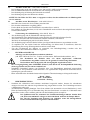
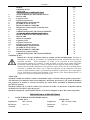
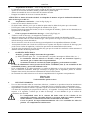
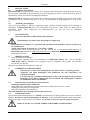
GENERALITÀ
Prima di procedere all’installazione leggere attentamente questa documentazione.
L’installazione ed il funzionamento dovranno essere conformi alla regolamentazione di
sicurezza del paese di installazione del prodotto. Tutta l’operazione dovrà essere eseguita a
regola d’arte. Il mancato rispetto delle norme di sicurezza, oltre a creare pericolo per
l’incolumità delle persone e danneggiare le apparecchiature, farà decadere ogni diritto di
intervento in garanzia.
L’apparecchio non è destinato ad essere usato da persone (bambini compresi) le cui capacità
fisiche sensoriali o mentali siano ridotte, oppure con mancanza di esperienza o di conoscenza, a
meno che esse abbiano potuto beneficiare, attraverso l’intermediazione di una persona
responsabile della loro sicurezza, di una sorveglianza o di istruzioni riguardanti l’uso
dell’apparecchio. I bambini devono essere sorvegliati per sincerarsi che non giochino con
l’apparecchio (CEI EN 60335-1: 08).
APPLICAZIONI
I sistemi Fekalift sono indicati esclusivamente per il trattamento di acque di scarico, carta igienica e
deiezioni fecali. Altri materiali o sostanze solide (ovatta, tamponi, assorbenti, preservativi, capelli,
panni in cotone) o il pompaggio di liquidi come solventi oppure oli possono causare danni al sistema e
diminuire le prestazioni previste in garanzia.
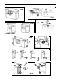
I sistemi Fekalift 100-A e 200-A devono essere collegati ad un WC con scarico orizzontale secondo le
norme EN33 o EN37. (fig.A-D pag. 62)
I sistemi Fekalift 300-A sono delle stazioni di sollevamento ad incasso adatte esclusivamente per WC
sospesi.
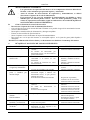
FEKALIFT 100-A / FEKALIFT 200-A
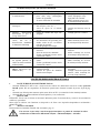
1. DATI TECNICI E LIMITAZIONI D’USO
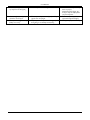
Fekalift 100-A
Fekalift 200-A
Collegamento a: WC + lavabo Collegamento a: WC + Lavabo + Doccia
Scarico verticale:
max. 5 m.
Scarico verticale:
max 5 m.

ITALIANO
2
2. INSTALLAZIONE
2.1 Collegamento al WC
FEKALIFT 100-A : il sistema deve essere collegato ad un WC con scarico orizzontale, come indicato nella
fig.B pag.62. Per collegare un lavandino, è necessario utilizzare l'ingresso sul lato sinistro del coperchio,
guardando il trituratore. Utilizzare gli accessori forniti per collegare il tubo.
FEKALIFT 200-A : il sistema deve essere collegato ad un WC con scarico orizzontale, chiudendo
l’ingresso laterale inferiore non utilizzato, come indicato nella fig.E-F pag.62. Per il collegamento degli
ingressi ausiliari guarda fig. F pag 62.
2.2 Collegamento allo scarico
Inserire a pressione l’estremità grande della curva nell’uscita dell’apparecchio, ruotarla nella direzione
desiderata e fissarla con una fascetta. Per le FEKALIFT 100-A inserire a pressione anche la bocca B
sull’altra estremità e fissarla sempre con una fascetta. Collegare quindi lo scarico alla bocca della pompa e
fissarlo con una fascetta (fig.C-G pag.62).
3.
ALLACCIAMENTO ELETTRICO:
Attenzione: osservare sempre le norme di sicurezza!
I collegamenti elettrici devono essere eseguiti dopo il montaggio del sistema!
– L’installazione elettrica deve essere effettuata da un elettricista esperto, autorizzato che se ne
assume tutte le responsabilità.
–
Collegare il sistema ad una presa 10 – 16A 2poli + MESSA A TERRA.
– La presa deve fornire unicamente l’alimentazione del sistema e dev’essere collegata per le FEKALIFT
100-A ad un interruttore automatico di sicurezza
e per le FEKALIFT 200-A ad un interruttore
differenziale altamente sensibile calibrati su 30 mA.
4. MESSA IN FUNZIONE
– Effettuare il collegamento alla presa di corrente.
– Azionare una volta lo sciaquone, il sistema deve avviarsi automaticamente e funzionare per le
FEKALIFT 100-A e per le FEKALIFT 200-A entro un periodo di 5 max. 30 sec. Se il tempo di
avviamento supera i 35 sec. controllare che il tubo di scarico non sia schiacciato o intasato.
Dopo tale operazione è possibile utilizzare la toilette come un classico WC.
5. MANUTENZIONE E PULIZIA
– L’esecuzione di interventi di riparazione sul motore o sui componenti elettrici
possono essere eseguiti solo da personale specializzato e autorizzato.
– Tutti gli interventi di riparazione e manutenzione si devono effettuare solo dopo aver
scollegato l’apparecchio dalla rete di alimentazione elettrica.
– Nella maggior parte dei casi gli eventuali malfunzionamenti sono provocati da cause
minime risolvibili, il più delle volte, da soli. Per tutti gli altri problemi rivolgersi ad
un centro riparazioni autorizzato (seguire le indicazioni della tabella RICERCA E
SOLUZIONE INCONVENIENTI).
5.1 Rimozione del trituratore dal vaso del WC
– Scollegare l’apparecchio dalla rete di alimentazione elettrica.
– Chiudere il rubinetto ad angolo dell’alimentazione e rimuovere la maggior parte dell’acqua dal sifone
del bacino del WC.
– Staccare il tubo di mandata e i tubi di alimentazione.
– Rimuovere l’apparecchio dal WC.
Ripristinare l’alimentazione elettrica soltando dopo aver concluso il rimontaggio del sistema.
5.2 Corpi estranei
Se un corpo estraneo entrasse nel Fekalift attraverso la toilette, si potrà risolvere prontamente l’incoveniente
senza necessità di contattare il personale dell’assistenza: staccare innanzitutto la spina di alimentazione
dalla presa di corrente; attraverso l’ingresso del WC e con l’aiuto di un cacciavite oppure di un filo di ferro
rimuovere il corpo estraneo. Attenzione non perforare la bocca della pompa!
Le lame sono molto affilate, NON INTRODURRE MAI LA MANO NELL’APPARECCHIO!

ITALIANO
3
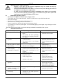
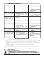
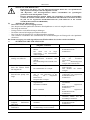
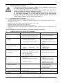
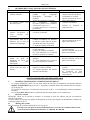
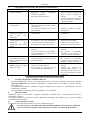
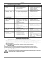
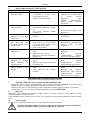
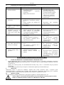
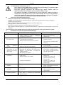
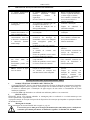
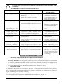
6. RICERCA E SOLUZIONE INCONVENIENTI
INCONVENIENTI VERIFICHE (possibili cause) RIMEDI
1. Il sistema si disinserisce in
maniera anomala.
– Il sistema ha continuato a pompare
per troppo tempo (interruttore
termico di sicurezza).
– Errore del sistema di comando.
– Estrarre la spina dalla presa di
corrente. Attendere un’ora e
ricollegare il sistema.
Contattare altrimenti un
servizio di assistenza clienti
autorizzato.
2. Il sistema si inserisce con
interruzioni.
– Gli impianti sanitari collegati sono
privi di tenuta (valvolame, ecc...)
– La valvola di ritegno non si chiude
perfettamente.
– Controllare l’impianto.
– Pulire o sostituire la valvola di
ritegno.
3. Il motore funziona in
modo discontinuo e
l’acqua defluisce molto
lentamente.
– Il foro di ventilazione nel coperchio
è intasato.
– Pulire il foro di ventilazione.
4. Il motore funziona
correttamente, ma non si
disinserisce rimanendo in
funzione per molto tempo.
– Altezza o lunghezza eccessive dello
scarico o presenza di troppe curve
nelle tubazioni con relativa perdita
di pressione.
– Il fondo della pompa è intasato.
– Controllare l’impianto.
Contattare altrimenti un
servizio di assistenza clienti
autorizzato.
5. Il motore non si avvia. – Il sistema non è collegato alla rete
elettrica.
– La presa di corrente è danneggiata.
– Esiste un problema con il motore
oppure con il sistema di controllo.
– Collegare il sistema alla rete
elettrica.
Contattare altrimenti un
servizio di assistenza clienti
autorizzato.
6. Il motore funziona con un
forte rumore di sbattimento
oppure emette un ronzio
non funzionando.
– Il motore è bloccato da un corpo
estraneo.
– Esiste un problema con il motore
oppure con il sistema di controllo.
– Rimuovere il corpo estraneo.
Contattare altrimenti un
servizio di assistenza clienti
autorizzato.
7. Per FEKALIFT 200-A:
ritorno di acqua torbida
nella doccia.
– La doccia è troppo bassa rispetto al
sistema Fekalift.
– Le valvole di ritegno degli ingressi
laterali sono intasate.
– Controllare l’installazione del
sistema.
– Pulire le valvole di ritegno
dall’esterno, altrimenti
contattare un servizio clienti
autorizzato.
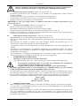
STAZIONE DI SOLLEVAMENTO FEKALIFT 300-A
1. DATI TECNICI E LIMITAZIONI D’USO
– Il sistema FEKALIFT 300-A è una piccola stazione di sollevamento di dimensioni estremamente ridotte
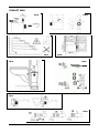
adatta SOLO per WC sospesi, da installare dietro a comuni moduli a parete, fig.A-B pag.63
– Il sistema è usato per lo smaltimento di acque reflue da un WC ed eventualmente da ulteriori impianti
sanitari.
– Il sistema NON è destinato all’utilizzo in ambienti pubblici e/o commerciali.
2. INSTALLAZIONE
FEKALIFT 300-A è un sistema ad incasso. Il montaggo può essere eseguito solo ed esclusivamente da un
tecnico qualificato e specializzato.
La piccola stazione di sollevamento è fornita di dispositivi di ritenuta che impediscono il distacco accidentale
dell’unità dal WC.
2.1 Montaggio del sistema
Per il montaggio del sistema Fekalift 300-A seguire pag.63
E’ necessario prevedere una porta d’ispezione/manutenzione con feritoie di ventilazione
nel telaio avente almeno le seguenti dimensioni: L=500 mm H= 420 mm!

ITALIANO
4
2.2 Collegamento al WC – vedi fig.E-F pag.63
– L’anello di tenuta è idoneo per il collegamento di un tubo di scarico WC da 100 mm.
– Spalmare sull’estremità del tubo da inserire del gel lubrificante oppure del sapone liquido.
– Allineare l’anello di tenuta in direzione dell’estremità del tubo.
– Spingere l’anello di tenuta sull’estremità del tubo.
ATTENZIONE: l’altezza del WC dev’essere adattata in modo che il tubo di scarico presenti una
pendenza minima del 3%.
2.3 Collegamento ad un lavabo – vedi fig.G pag.63
– Con l’aiuto di un taglierino ritagliare l’apertura in alto.
– Non lasciare bordi affilati eseguendo un’accurata sbavatura della parte tagliata.
– Impiegare per il tubo del coperchio un manicotto d’ingresso (rif.A fig.G)
– Inserire lo scarico del lavabo (Ø 32) nel manicotto d’ingresso e fissarlo con le fascette date in dotazione
(rif.B fig.G).
2.4 Preparazione della tubazione di scarico – vedi fig.H pag.63
– Impiegare la curva di scarico e il manicotto d’ingresso (rif.F).
– Inserire il manicotto d’ingresso sulla curva di scarico, usando una fascetta di fissaggio (rif.B).
– Allineare e inserire il tutto nel tubo flessibile nero come indicato nella fig.G. Fissare con una fascetta la
base della curva di scarico.
– Se necessario, tagliare la curva di scarico per adattarla al corrispondente diametro del tubo.
– Consigliamo di montare una valvola di scarico sul punto più basso della tubazione di scarico, in modo
da poter svuotare il tubo di mandata per eseguire eventuali lavori di manutenzione sul sistema.
– Per evitare un’aspirazione a vuoto del sifone è necessario prevedere una condotta di aereazione oppure
provvedere ad aumentare il diametro dello scarico orizzontale.
3.
ALLACCIAMENTO ELETTRICO:
Attenzione: osservare sempre le norme di sicurezza!
(es. DIN VDE 0100 parte 701 – Locali umidi e baganti, interruttori differenziali, ecc...)
– L’installazione elettrica deve essere effettuata da un elettricista esperto, autorizzato
che se ne assume tutte le responsabilità.
– La presa di corrente dev’essere applicata in maniera appropriata e liberamente
accessibile.
– La linea di alimentazione dev’essere dotata di MESSA A TERRA (classe I) con un fusibile ad alta
sensibilità (30 mA) con una protezione calibrata su 16A.
– Un eventuale cavo danneggiato dovrà essere esaminato dal costruttore o dal servizio di assistenza clienti
in quanto dovrà essere sostituito immediatamente perchè costituisce un pericolo per la sicurezza. Prima
di effettuare qualsiasi intervento scollegare l’alimentazione elettrica del sistema!
– Il collegamento dei cavi elettrici deve avvenire rispettando rigorosamente la seguente corrispondenza:
Marrone = fase
Blu = neutro
Verde/Giallo = messa a terra
4. MESSA IN FUNZIONE
– Dopo che tutti i collegamenti elettrici e sanitari sono stati eseguiti, è possibile azionare gli impianti
collegati ,uno dopo l’altro,per qualche minuto. Verificare che i collegamenti siano assolutamente aciutti!
– Successivamente azionare lo sciacquone: l’apparecchio si avvia automaticamente e funziona a seconda
dell’altezza della mandata per un periodo compreso tra i 10 e i 30 secondi. Con un tempo di
funzionamento superiore a 35 secondi verificare che lo scarico non sia piegato oppure che il foro di
aereazione non sia intasato.
– La cassetta dello sciacquone e il valvolame degli impianti sanitari collegati devono
presentare una tenuta assolutamente perfetta, in quanto eventuali perdite anche minime
provocano interventi indesiderati della pompa.
– Chiudere la porta di ispezione/manutenzione solo se tutti i test eseguiti hanno ottenuto
risultati pienamente soddisfacenti.

ITALIANO
5
5. MANUTENZIONE E PULIZIA
– L’esecuzione di interventi di riparazione sul motore o sui componenti elettrici possono
essere eseguiti solo da personale specializzato e autorizzato.
– Tutti gli interventi di riparazione e manutenzione si devono effettuare solo dopo aver
scollegato l’apparecchio dalla rete di alimentazione elettrica.
– Nella maggior parte dei casi gli eventuali malfunzionamenti sono provocati da cause
minime risolvibili, il più delle volte, da soli . Per tutti gli altri problemi rivolgersi ad un
centro riparazioni autorizzato (seguire le indicazioni della tabella RICERCA E
SOLUZIONE INCONVENIENTI).
5.1 Smontaggio della stazione di sollevamento.
– Scollegare l’apparecchio dalla rete di alimentazione elettrica.
– Chiudere la valvola di arresto della cassetta dello sciacquone. Togliere quanta più acqua possibile dalla
cassetta.
– Svuotare il tubo montante.
– Staccare eventuali tubi di alimentazione e scarico collegati.
– Rimuovere le due viti di fissaggio inferiore.
– Estrarre l’apparecchio attraverso l’appertura di ispezione/manutenzione.
– Per chiudere nuovamente il coperchio del sistema si consiglia di spalmare sulla guarnizione in gomma
del sapone liquido o del detersivo.
Ripristinare l’alimentazione elettrica soltando dopo aver concluso il rimontaggio del sistema.
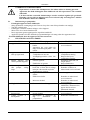
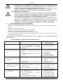
6. RICERCA E SOLUZIONE INCONVENIENTI
INCONVENIENTI VERIFICHE (possibili cause) RIMEDI
1. Il sistema si blocca – Un corpo estraneo blocca la lama.
– Il sistema ha funzionato troppo a lungo / la
protezione termica è intervenuta.
– Contattare un servizio di
assistenza clienti autorizzato.
2. Il sistema si avvia
sempre da solo.
– La cassetta dello sciacquone o il valvolame
collegato sono privi di tenuta.
– La valvola di ritegno non chiude a tenuta.
– Sostituire la guarnizione della
cassetta dello sciaquone e del
valvolame.
– Pulire o sostituire la valvola
di ritegno.
3. Il motore funziona,
ma l’acqua scende
lentamente.
– Il filtro è intasato.
– Il coperchio del ventilatore è intasato.
– Smontare l’apparecchio,
pulire il filtro.
– Pulire il coperchio del
ventilatore.
4. Il motore funziona
senza sosta oppure
pompa per molto
tempo.
– Altezza o larghezza di mandata troppo ampia
o presenza di troppe curve nelle tubazioni con
relativa perdita di pressione.
– Fondo della pompa intasato.
– Controllare l’impianto.
Contattare altrimenti un
servizio di assistenza clienti
autorizzato.
5. Il motore non si
avvia.
– Il sistema non è collegato alla rete elettrica.
– Il cavo di alimentazione è difettoso.
– Ci sono danni al motore.
– Collegare il sistema alla rete
elettrica.
– Contattare un servizio di
assistenza clienti autorizzato.
– Contattare un servizio di
assistenza clienti autorizzato.
6. Forti rumori
durante il
funzionamento.
– Corpi estranei nel sistema. – Staccare l’apparecchio dalla
corrente, smontarlo, aprirlo e
rimuovere i corpi estranei.
7. Il motore produce
solo un ronzio e
non funziona.
– Condensatore difettoso oppure ci sono danni
al motore.
– Contattare un servizio di
assistenza clienti autorizzato.
8. L’acqua entra nel
piatto doccia.
– Il piatto doccia è stato installato troppo basso
rispetto alla stazione di sollevamento.
– Verificare l’installazione.

ENGLISH
6
INDEX page
GENERAL
6
APPLICATIONS
6
FEKALIFT 100-A / FEKALIFT 200-A
1. TECHNICAL DATA AND LIMITATIONS OF USE
6
2. INSTALLATION
7
2.1 Connection to toilet
7
2.2 Connection to discharge
7
3. ELECTRICAL CONNECTION
7
4. COMMISSIONING
7
5. MAINTENANCE AND CLEANING
7
5.1 Removing the grinder from the toilet pan
7
5.2 Foreign bodies
7
6. TROUBLESHOOTING
8
FEKALIFT 300-A LIFTING STATION
1. TECHNICAL DATA AND LIMITATIONS OF USE
8
2. INSTALLATION
8
2.1 System assembly
8
2.2 Connection to toilet
9
2.3 Connection to a washbasin
9
2.4 Preparation of the discharge pipe
9
3. ELECTRICAL CONNECTION
9
4. COMMISSIONING
9
5. MAINTENANCE AND CLEANING
10
5.1 Dismantling the lifting station
10
6. TROUBLESHOOTING
10
GENERAL
Read this documentation carefully before installation. Installation and operation must
comply with the local safety regulations in force in the country in which the product is
installed. Everything must be done in a workmanlike manner. Failure to respect the safety
regulations not only causes risk to personal safety and damage to the equipment, but invalidates
every right to assistance under guarantee.
The appliance is not intended to be used by persons (including children) with reduced physical,
sensory or mental capacities, or who lack experience or knowledge, unless, through the
mediation of a person responsible for their safety, they have had the benefit of supervision or of
instructions on the use of the appliance. Children must be supervised to ensure that they do not
play with the appliance (CEI EN 60335-1: 08).
APPLICATIONS
Fekalift systems are indicated exclusively for the processing of waste water, toilet paper and faecal
matter. Other materials or solid substances (cotton wool, tampons, sanitary towels, condoms, hair,
cotton cloths) or the pumping of liquids such as solvents or oils may cause damage to the system and
decrease the performance contemplated under guarantee.
The Fekalift 100-A and 200-A systems must be connected to a toilet with horizontal outlet according to
standards EN33 or EN37. (fig.A-D page 62)
Fekalift 300-A systems are built-in lifting stations suitable exclusively for suspended toilets.
FEKALIFT 100-A / FEKALIFT 200-A
1. TECHNICAL DATA AND LIMITATIONS OF USE
Fekalift 100-A
Fekalift 200-A
Connection to:
Toilet + Wash basin Connection to: Toilet + Wash basin + Shower
Vertical outlet:
max. 5 m.
Vertical outlet:
max. 5 m.

ENGLISH
7
2. INSTALLATION
2.1 Connection to toilet
FEKALIFT 100-A : the system must be connected to a toilet with horizontal outlet, as indicated in
fig.B page 62. To connect a washbasin it is necessary to use the input on the left side of the cover, looking
towards the grinder. Use the accessories supplied to connect the pipe.
FEKALIFT 200-A : the system must be connected to a toilet with horizontal outlet, closing the unused
lower side inlet, as indicated in fig.E-F page 62. To connect the auxiliary inputs see fig. F page 62.
2.2 Connection to discharge
Push the large end of the bend into the outlet of the appliance, turn it in the desired direction and fix it with a
clamp. For FEKALIFT 100-A push also mouth B onto the other end and fix it too with a clamp. Then
connect the discharge to the pump outlet and fix it with a clamp (fig. C-G page 62).
3.
ELECTRICAL CONNECTION
Attention: always respect the safety regulations!
The electrical connections must be made after assembly of the system!
– Electrical installation must be carried out by an expert, authorised electrician, who takes on all
responsibility.
–
Connect the plug to a 10 – 16A 2-pole EARTHED socket.
– The socket must supply only the power to the system; for FEKALIFT 100-A it must be connected to an
automatic safety switch
and for FEKALIFT 200-A to a highly sensitive differential switch calibrated at
30 mA.
4. COMMISSIONING
–
Connect to the power socket.
–
Flush the toilet once; the system must start automatically, FEKALIFT 100-A and FEKALIFT 200-A
within a period of 5 max. 30 sec. If the start time exceeds 35 sec., check that the discharge pipe is not
crushed or blocked.
After this operation the toilet can be used just like an ordinary one.
5. MAINTENANCE AND CLEANING
–
Repairs to the motor or the electric components may be carried out only by
specialised and authorised personnel.
– All repair and maintenance work must be carried out only after having disconnected
the appliance from the power supply mains.
– In most cases any malfunctions are due to minimum causes which you can usually
solve yourself. For all other problems apply to an authorised repair centre (follow the
instructions in the TROUBLESHOOTING table).
5.1 Removing the grinder from the toilet pan
– Disconnect the appliance from the power supply mains.
– Turn off the corner supply tap and remove most of the water from the siphon of the toilet basin.
– Disconnect the delivery pipe and the supply pipes.
– Remove the appliance from the toilet.
Turn the electric power back on only after having concluded reassembly of the system.
5.2 Foreign bodies
If a foreign body gets into the Fekalift through the toilet, the problem can be solved easily without having to
contact service personnel: first of all take the plug out of the socket; remove the foreign body from the
toilet inlet with the aid of a screwdriver or a piece of wire. Take care not to make a hole in the pump inlet!
The blades are very sharp, NEVER PUT YOUR HAND INTO THE APPLIANCE!

ENGLISH
8
6. TROUBLESHOOTING
FAULTS CHECKS (possible causes) REMEDIES
1. The system cuts out
abnormally.
– The system has continued
pumping too long (thermal safety
switch).
– Error in the control system.
– Take the plug out of the
socket. Wait an hour and
reconnect the system.
Otherwise contact an
authorised customer service
centre.
2. The system switches on
with interruptions.
– The connected plumbing systems
are not sealed (valves, etc.).
– The check valve is not closing
properly.
– Check the system.
–
Clean or change the check
valve.
3. The motor works
discontinuously and the
water is flowing very
slowly.
– The ventilation hole in the cover
is blocked.
– Clean the ventilation hole.
4. The motor is working
correctly but it does not
switch off, remaining
operating for a long time.
– Discharge too high or too long or
presence of too many bends in the
pipes with consequent loss of
pressure.
– The bottom of the pump is
clogged.
– Check the system.
Otherwise contact an
authorised customer service
centre.
5. The motor does not start. – The system is not connected to
the power mains.
– The power socket is damaged.
– There is a problem with the motor
or with the control system.
– Connect the system to the
power mains.
Otherwise contact an
authorised customer service
centre.
6. The motor is working
with a loud knocking
noise, or it is buzzing
and not working.
– The motor is blocked by a foreign
body.
– There is a problem with the motor
or with the control system.
– Remove the foreign body.
Otherwise contact an
authorised customer service
centre.
7. For FEKALIFT 200-A:
cloudy water returning
into the shower.
– The shower is too low with
respect to the Fekalift system.
– The check valves of the side
inlets are clogged.
– Check the system installation.
–
Clean the check valves from
the outside, otherwise contact
an authorised customer
service centre
FEKALIFT 300-A LIFTING STATION
1. TECHNICAL DATA AND LIMITATIONS OF USE
– The FEKALIFT 300-A system is a small lifting station with extremely compact dimensions, suitable
ONLY for suspended toilets, to be installed behind ordinary wall modules, fig.A-B page 63
– The system is used for the disposal of waste water from a toilet and possibly from other plumbing
equipment.
– The system is NOT intended for use in public and/or commercial settings.
2. INSTALLATION
FEKALIFT 300-A is a built-in system. It may be fitted only and exclusively by a qualified, specialised
technician.
The small lifting station is equipped with retaining devices which prevent the unit becoming accidentally
detached from the toilet.
2.1 System assembly
To assembly the Fekalift 300-A system follow see page 63
An inspection/maintenance hatch must be provided with ventilation slots in the frame
having at least the following dimensions: L=500 mm H= 420 mm!

ENGLISH
9
2.2 Connection to the toilet - see fig.E-F page 63
– The sealing ring is suitable for connecting a 100 mm toilet discharge pipe.
– Spread some lubricating gel or liquid soap on the end of the pipe to be inserted.
– Align the sealing ring in the direction of the end of the pipe.
– Push the sealing ring onto the end of the pipe.
ATTENTION: the height of the toilet must be adapted so that the discharge pipe has a minimum
slope of 3%.
2.3 Connection to a wash basin - see fig.G page 63
– Cut the top opening with the aid of a craft knife.
– Trim the cut part accurately so as not to leave any sharp edges.
– Use an inlet sleeve for the cover pipe (ref.A fig.G)
–
Insert the wash basin outlet (Ø 32) in the inlet sleeve and fix it with the clamps provided (ref.B fig.G).
2.4 Preparation of the discharge pipe - see fig.H page 63
– Use the outlet bend and the inlet sleeve (ref.F).
– Fit the inlet sleeve onto the outlet bend, using a fixing clamp (ref.B).
– Align and insert the whole in the black flexible pipe as indicated in fig.G. Fix the base of the outlet bend
with a clamp.
– If necessary, cut the outlet bend to adapt it to the corresponding diameter of the pipe.
– We recommend fitting a discharge valve on the lowest point of the discharge pipe, so as to be able to
empty the delivery pipe when carrying out maintenance work on the system.
– To avoid idle suction of the siphon it is necessary to provide a ventilation duct or to increase the
diameter of the horizontal outlet.
3.
ELECTRICAL CONNECTION:
Attention: always respect the safety regulations!
(e.g. DIN VDE 0100 part 701 – Damp and wet rooms, differential switches, etc….)
– Electrical installation must be carried out by an expert, authorised electrician, who
takes on all responsibility.
– The power socket must be applied in an appropriate way and be freely accessible.
–
The power line must be EARTHED (class I) with a high-sensitivity fuse (30 mA) and protection
calibrated at 16A.
–
If any cable is damaged it must be examined by the manufacturer or by the customer service centre since
it is a safety hazard and must be replaced immediately. Before doing any work, disconnect the power
supply to the system!
– When connecting the electric cables the following correspondence must be strictly respected:
Brown = phase
Blue = neutral
Yellow/Green = earth
4. COMMISSIONING
–
After all the electrical and plumbing connections have been made, the connected systems may be started
up, one after the other, for a few minutes. Ensure that the connections are absolutely dry!
–
Then flush the toilet: the appliance starts automatically and works for a period of 10 to 30 seconds,
depending on the height of delivery. If the operating time is longer than 35 seconds, check that the outlet
is not bent or the ventilation hole clogged.
– The flush tank and the valves of the connected plumbing systems must have an
absolutely perfect seal, since any leaks, even of minimum extent, cause undesired
operation of the pump.
– Close the inspection/maintenance hatch only if all the tests performed have obtained
perfectly satisfactory results.

ENGLISH
10
5. MAINTENANCE AND CLEANING
–
Repairs to the motor or the electric components may be carried out only by
specialised and authorised personnel.
– All repair and maintenance work must be carried out only after having disconnected
the appliance from the power supply mains.
– In most cases any malfunctions are due to minimum causes which you can usually
solve yourself. For all other problems apply to an authorised repair centre (follow the
instructions in the TROUBLESHOOTING table).
5.1 Dismantling the lifting station.
– Disconnect the appliance from the power supply mains.
– Turn off the stop valve of the flush tank. Remove as much water as possible from the tank.
– Drain the stand pipe.
– Disconnect any connected supply and discharge pipes.
– Remove the two retaining screws on the bottom.
– Extract the appliance through the inspection/maintenance hatch.
– To close the cover of the system again we recommend applying some liquid soap or detergent on the
rubber gasket.
Turn the electric power back on only after having concluded reassembly of the system.
6. TROUBLESHOOTING
FAULTS CHECKS (possible causes) REMEDIES
1. The system is blocked. – A foreign body is blocking the
blade.
– The system has been operating
too long / the thermal protection
has tripped.
–
Contact an authorised
customer service centre.
2. The system always starts
by itself.
–
No seal in the flush tank or
connected valves.
–
The check valve is not closing
with a seal.
– Change the gasket of the
flush tank and of the valves.
– Clean or change the check
valve.
3. The motor is working,
but the water is going
down slowly.
–
The filter is clogged.
–
The fan cover is clogged.
–
Dismantle the appliance,
clean the filter.
–
Clean the fan cover.
4. The motor is working
uninterruptedly or
pumping for a long time.
–
Delivery too high or too wide or
presence of too many bends in the
pipes with consequent loss of
pressure.
–
Pump bottom clogged.
–
Check the system.
Otherwise contact an
authorised customer service
centre.
5. The motor does not start. – The system is not connected to
the power mains.
– Faulty supply cable.
–
Damage to the motor.
– Connect the system to the
power mains.
– Contact an authorised
customer service centre.
– Contact an authorised
customer service centre.
6. Loud noises during
operation.
–
Foreign bodies in the system. – Disconnect the appliance
from the power supply,
disassemble it, open it and
remove the foreign bodies.
7. The motor is only
making a buzzing noise
and is not working.
–
Faulty capacitor or damage to the
motor.
–
Contact an authorised
customer service centre.
8. Water is getting into the
shower tray.
–
The shower tray has been
installed too low with respect to
the lifting station.
–
Check installation.

DEUTSCH
11
INHALT Seite
ALLGEMEINES
11
ANWENDUNGEN
11
FEKALIFT 100-A / FEKALIFT 200-A
1. TECHNISCHE DATEN UND EINSATZBESCHRÄNKUNGEN
11
2. INSTALLATION
12
2.1 Anschluss an das WC
12
2.2 Anschluss an den Abfluss
12
3. ELEKTROANSCHLUSS
12
4. INBETRIEBSETZUNG
12
5. WARTUNG UND REINIGUNG
12
5.1 Ausbauen des Häckselwerks aus der WC-Schüssel
12
5.2 Fremdkörper
12
6. STÖRUNGSSUCHE UND LÖSUNGEN
13
HEBEANLAGE FEKALIFT 300-A
1. TECHNISCHE DATEN UND EINSATZBESCHRÄNKUNGEN
13
2. INSTALLATION
13
2.1 Montage des Gerätes
13
2.2 Anschluss an das WC
14
2.3 Anschluss an ein Waschbecken
14
2.4 Vorbereitung der Abflussleitung
14
3. ELEKTROANSCHLUSS
14
4. INBETRIEBSETZUNG
14
5. WARTUNG UND REINIGUNG
15
5.1 Ausbauen der Hebeanlage
15
6. STÖRUNGSSUCHE UND LÖSUNGEN
15
ALLGEMEINES
Bevor mit der Installation begonnen wird, muss diese Anleitung aufmerksam
durchgelesen werden.
Installation und Funktion müssen den Sicherheitsvorschriften des Anwenderlands entsprechen.
Alle Operationen müssen kunstgerecht durchgeführt werden. Die Nichteinhaltung dieser
Vorschriften stellt nicht nur eine Gefahr für Personen dar und kann Sachschäden verursachen,
sondern lässt außerdem auch jeden Garantieanspruch verfallen.
Das Gerät darf nicht von Personen (einschließlich Kindern) benutzt werden, deren sensorische
oder mentale Fähigkeiten eingeschränkt sind, oder denen es an Erfahrung oder Kenntnissen
mangelt, sofern ihnen nicht eine für ihre Sicherheit verantwortliche Personen zur Seite steht,
die sie überwacht oder beim Gebrauch des Gerätes anleitet. Kinder nicht unbeaufsichtigt in die
Nähe des Gerätes lassen und sicherstellen, dass sie nicht damit herumspielen
(CEI EN 60335-1: 08).
ANWENDUNGEN
Die Geräte Fekalift sind ausschließlich zur Behandlung von Abwässern, Toilettenpapier und Fäkalien
bestimmt. Anderes Material oder Festkörper (Watte, Tampons, Monatsbinden, Kondome, Haare,
Baumwolltücher) oder das Pumpen von Flüssigkeiten, wie Lösemittel oder Öle können das Gerät
schädigen und die garantierten Leistungen verringern.
Die Geräte Fekalift 100-A und 200-A müssen an ein WC mit horizontalem Abfluss gemäß EN33 oder
EN37 angeschlossen werden. (Abb.A-D Seite 62)
Die Geräte Fekalift 300-A sind Einbau-Hebeanlagen für ausschließlich wandhängende WCs.
FEKALIFT 100-A / FEKALIFT 200-A
1. TECHNISCHE DATEN UND EINSATZBESCHRÄNKUNGEN
Fekalift 100-A
Fekalift 200-A
Anschluss an: WC + Waschbecken Anschluss an: WC + Waschbecken + Dusche
Vertikaler Abfluss:
max. 5 m
Vertikaler Abfluss:
max 5 m

DEUTSCH
12
2. INSTALLATION
2.1 Anschluss an das WC
FEKALIFT 100-A: Das Gerät muss an ein WC mit horizontalem Abfluss angeschlossen werden, siehe
Abb.B Seite 62. Um ein Spülbecken anzuschließen den Eingang an der linken Seite des Deckels, vom
Häckselwerk aus gesehen, verwenden. Dazu das für den Anschluss des Rohrs gelieferte Zubehör benutzen.
FEKALIFT 200-A: Das Gerät muss an ein WC mit horizontalem Abfluss angeschlossen werden, wobei der
nicht benutzte seitliche Zugang verschlossen wird, siehe Abb.E-F Seite 62. Für den Anschluss der
Hilfseingänge siehe Abb. F auf Seite 62.
2.2 Anschluss an den Abfluss
Das größere Ende des Kniestücks in den Ausgang des Gerätes eindrücken, in die gewünschte Richtung
drehen und mit einer Rohrschelle befestigen. Bei FEKALIFT 100-A den Stutzen B am anderen Ende
eindrücken und ebenfalls mit einer Rohrschelle befestigen. Den Abfluss an den Stutzen der Pumpe
anschließen und mit einer Rohrschelle befestigen (Abb. C-G Seite 62).
3.
ELEKTROANSCHLUSS:
Achtung: stets die Sicherheitsvorschriften einhalten!
Die elektrischen Anschlüsse werden nach der Montage des Gerätes ausgeführt!
– Die Installation der Elektrik muss von einem zugelassenen, erfahrenen Fachelektriker ausgeführt
werden, der die gesamte Verantwortung übernimmt.
–
Das Gerät an eine Steckdose 10 – 16A zweipolig + ERDUNG anschließen.
– Die Steckdose soll ausschließlich das Gerät versorgen und bei den FEKALIFT 100-A an einen
Fehlerstromschutzschalter
und bei den FEKALIFT 200-A an einen hochempfindlichen
Differentialschutzschalter, beide auf 30 mA kalibriert, angeschlossen sein.
4. INBETRIEBSETZUNG
–
An die Steckdose anschließen.
–
Die Wasserspülung einmal betätigen, das Gerät muss sich automatisch einschalten und bei den
FEKALIFT 100-A und bei den FEKALIFT 200-A innerhalb von 5 bis max. 30 sec. funktionieren.
Falls die Anlaufzeit länger als 35 sec. dauert, muss kontrolliert werden, ob das Abflussrohr gequetscht
oder verstopft ist.
Danach kann die Toilette wie ein normales WC benutzt werden.
5. WARTUNG UND REINIGUNG
–
Reparaturen am Motor oder den Elektrokomponenten dürfen nur von
spezialisiertem und zugelassenem Fachpersonal durchgeführt werden.
– Alle Reparatur- und Wartungsarbeiten dürfen ausschließlich bei spannungslos
gemachtem Gerät durchgeführt werden.
– Etwaige Funktionsstörungen können häufig auf geringfügige Ursachen
zurückgeführt werden, die meistens selbst behoben werden können. Für alle anderen
Probleme wenden Sie sich an ein zugelassenes Kundendienstzentrum (siehe Hinweise
in der Tabelle STÖRUNGSSUCHE UND ABHILFEN).
5.1 Ausbauen des Häckselwerks aus der WC-Schüssel
– Das Gerät von der Netzversorgung trennen.
– Das Eckventil der Wasserversorgung schließen und die größtmögliche Wassermenge aus dem Siphon
der WC-Schüssel entfernen.
– Die Druckleitung und die Zuleitungen abtrennen.
– Das Gerät aus dem WC nehmen.
Die Stromversorgung erst nach abgeschlossenem Wiedereinbau des Gerätes wieder zuschalten.
5.2 Fremdkörper
Falls über die Toilette ein Fremdkörper in den Fekalift eingedrungen ist, kann dieser problemlos entfernt
werden, ohne den Kundendienst hinzuzuziehen: zunächst den Stecker aus der Steckdose nehmen; durch
den Zugang des WCs den Fremdkörper mit Hilfe eines Schraubendrehers oder eines Eisendrahts entfernen.
Darauf achten, dass der Stutzen der Pumpe nicht perforiert wird!
Die Messer sind sehr scharf, STECKEN SIE IHRE HÄNDE AUF KEINEN FALL IN DAS
GERÄT!

DEUTSCH
13
6. STÖRUNGSSUCHE UND LÖSUNGEN
STÖRUNGEN KONTROLLEN (mögliche Ursachen) ABHILFEN
1. Das Gerät schaltet
anomal ab.
–
Das Gerät hat zu lange Zeit weiter
gepumpt (Wärmeschutzschalter
ausgelöst).
–
Fehler des Steuersystems.
–
Den Stecker aus der Steckdose
nehmen. Eine Stunde abwarten
und das Gerät wieder
zuschalten.
Andernfalls eine zugelassene
Kundendienststelle
kontaktieren.
2. Das Gerät schaltet sich
mit Unterbrechungen
ein.
– Die angeschlossenen
Sanitäreinrichtungen sind undicht
(Ventile, usw.)
– Das Rückschlagventil schließt
nicht perfekt.
– Die Anlage kontrollieren.
– Das Rückschlagventil
reinigen oder auswechseln.
3. Der Motor läuft
ruckweise und das
Wasser fließt nur
langsam ab.
–
Das Belüftungsloch im Deckel ist
verstopft.
–
Das Belüftungsloch säubern.
4. Der Motor funktioniert
korrekt, schaltet aber
nicht ab und bleibt lange
Zeit in Betrieb.
–
Abfluss zu hoch oder zu lang, oder
zu viele Biegungen in der Leitung
mit folglichem Druckverlust.
–
Pumpenboden verstopft.
–
Die Anlage kontrollieren.
Andernfalls eine zugelassene
Kundendienststelle
kontaktieren.
5. Der Motor läuft nicht
an.
– Das Gerät ist nicht an das Netz
angeschlossen.
– Streckdose schadhaft.
–
Problem an Motor oder
Steuersystem.
– Das Gerät an das Netz
anschließen.
Andernfalls eine zugelassene
Kundendienststelle
kontaktieren.
6. Der Motor klappert laut
oder brummt und
funktioniert nicht.
–
Ein Fremdkörper blockiert den
Motor.
–
Problem an Motor oder
Steuersystem.
– Fremdkörper entfernen.
Andernfalls eine zugelassene
Kundendienststelle
kontaktieren.
7. Für FEKALIFT 200-
A: Rückfluss trüben
Wassers in die Dusche.
–
Die Dusche ist im Verhältnis zum
Fekalift zu niedrig installiert.
–
Die Rückschlagventile der
seitlichen Zugänge sind verstopft.
–
Die Installation der Anlage
kontrollieren.
–
Die Rückschlagventile von
außen reinigen oder eine
zugelassene
Kundendienststelle
kontaktieren.
HEBEANLAGE FEKALIFT 300-A
1. TECHNISCHE DATEN UND EINSATZBESCHRÄNKUNGEN
– FEKALIFT 300-A ist eine kleine Hebeanlage mit extrem geringen Abmessungen für NUR
wandhängende WCs, die hinter gewöhnlichen Wandmodulen installiert wird, Abb.A-B Seite 63
– Die Hebeanlage wird dazu benutzt, um Abwässer aus einem WC oder anderen Sanitäreinrichtungen
abzuführen.
– Sie eignet sich NICHT für den Einsatz in öffentlichen und/oder gewerblichen Räumen.
2. INSTALLATION
FEKALIFT 300-ist ein Einbaugerät. Der Einbau muss unbedingt durch einen qualifizierten Fachmann
erfolgen.
Die kleine Hebeanlage ist mit Halterungen ausgestattet, welche das unbeabsichtigte Ablösen der Einheit vom
WC verhindern.
2.1 Montage des Gerätes
Für den Einbau des Fekalift 300-A siehe Seite 63.
Für Inspektionen und Wartungseingriffe ist eine Klappe mit Belüftungsschlitzen
vorzusehen, welche die folgenden Mindestabmessungen haben soll: L=500 mm H= 420
mm!

DEUTSCH
14
2.2 Anschluss an das WC – siehe Abb.E-F Seite 63
– Der Dichtungsring ist für den Anschluss eines 100 mm WC-Abflussrohres bestimmt.
– Das einzuführende Rohrende mit Gleitmittel oder Flüssigseife schmieren.
– Den Dichtungsring in Richtung des Rohrendes ausrichten.
– Den Dichtungsring über das Rohrende schieben.
ACHTUNG: Die Höhe des WCs muss so angepasst werden, dass das Abflussrohr ein Mindestgefälle
von 3% aufweist.
2.3 Anschluss an ein Waschbecken – siehe Abb.G Seite 63
– Mit Hilfe eines Cutters die obere Öffnung ausschneiden.
– Die scharfen Schnittkanten sorgfältig glätten.
– Für das Rohr des Deckels eine Zulaufmuffe verwenden (Bez.A Abb.G)
–
Den Abfluss des Waschbeckens (Ø 32) in die Zulaufmuffe stecken und mit den mitgelieferten Schellen
sichern (Bez.B Abb.G).
2.4 Vorbereitung der Abflussleitung– siehe Abb.H Seite 63
– Die Abflussbiegung und die Zulaufmuffe anbringen (Bez.F).
– Die Zulaufmuffe in die Abflussbiegung stecken und mit einer Schelle befestigen (Bez.B).
– Das Ganze ausrichten und in den schwarzen Schlauch einführen, siehe Abb.G.
Die Basis der Abflussbiegung mit einer Schelle fixieren.
– Die Abflussbiegung kann nach Bedarf auf den jeweiligen Rohrdurchmesser zugeschnitten werden.
– Es empfiehlt sich am tiefsten Punkt der Abflussleitung ein Ablassventil zu installieren, damit die
Druckleitung für etwaige Wartungsarbeiten entleert werden kann.
– Um das Leerabsaugen des Siphons zu vermeiden, eine Belüftungsleitung vorsehen oder den
Durchmesser des horizontalen Abflusses vergrößern.
3.
ELEKTROANSCHLUSS:
Achtung: stets die Sicherheitsvorschriften einhalten!
(z.B. DIN VDE 0100 Teil 701 – Feucht- und Nassräume, Differentialschutzschalter, usw.)
– Die Installation der Elektrik muss von einem zugelassenen, erfahrenen
Fachelektriker ausgeführt werden, der die gesamte Verantwortung übernimmt.
– Die Steckdose muss fachgerecht und frei zugänglich angebracht werden.
–
Die Versorgungsleitung muss GEERDET (Klasse I) und durch eine hochempfindliche Sicherung
(30 mA) geschützt sein, die auf 16A kalibriert ist.
–
Schadhafte Gerätekabel müssen vom Hersteller oder vom Kundendienst umgehend ausgewechselt
werden, da sie eine potentielle Gefahr darstellen. Vor irgendwelchen Eingriffen am Gerät muss dieses
spannungslos gemacht werden!
– Beim Anschließen der Stromkabel müssen die folgenden Übereinstimmungen sichergestellt werden:
Braun = Phase
Blau = Neutralleiter
Grün/Gelb = Erdung
4. INBETRIEBSETZUNG
–
Nachdem alle elektrischen und sanitären Anschlüsse hergestellt wurden, können die verbundenen
Anlagen eine nach der anderen einige Minuten lang eingeschaltet werden. Die Verbindungen müssen
vollkommen trocken sein!
–
Anschließend die Spülung betätigen: Das Gerät schaltet sich automatisch ein und funktioniert je nach
Höhe der Druckleitung 10 bis 30 Sekunden lang. Bei einer Betriebszeit von mehr als 35 Sekunden muss
kontrolliert werden, ob der Abfluss geknickt oder das Belüftungsloch verstopft ist.
– Der Spülkasten und die Armaturen der Sanitäreinrichtungen müssen absolut dicht
sein, da bereits minimale Leckagen zu unerwünschtem Auslösen der Pumpe führen.
– Die Tür für Inspektion und Wartung erst schließen, wenn alle durchgeführten
Proben zufriedenstellende Ergebnisse erbracht haben.

DEUTSCH
15
5. WARTUNG UND REINIGUNG
– Reparaturen am Motor oder den Elektrokomponenten dürfen nur von spezialisiertem
und zugelassenem Fachpersonal durchgeführt werden.
– Alle Reparatur- und Wartungsarbeiten dürfen ausschließlich bei spannungslos
gemachtem Gerät durchgeführt werden.
– Etwaige Funktionsstörungen können häufig auf geringfügige Ursachen zurückgeführt
werden, die meistens selbst behoben werden können. Für alle anderen Probleme wenden
Sie sich an ein zugelassenes Kundendienstzentrum (siehe Hinweise in der Tabelle
STÖRUNGSSUCHE UND ABHILFEN).
5.1 Ausbauen der Hebeanlage.
– Das Gerät von der Netzversorgung trennen.
– Das Absperrventil des Spülkastens schließen. Den Spülkasten so weit wie möglich entleeren.
– Das Steigrohr entleeren.
– Etwaige Zufluss- und Abflussleitungen abhängen.
– Die beiden unteren Befestigungsschrauben ausbauen.
– Das Gerät durch die Inspektions- und Wartungsöffnen ausbauen.
– Zum erneuten Verschließen des Gerätedeckels die Gummidichtungen mit Flüssigseife oder Spülmittel
schmieren.
Die Stromversorgung erst nach abgeschlossenem Wiedereinbau des Gerätes wieder zuschalten.
6. STÖRUNGSSUCHE UND LÖSUNGEN
STÖRUNGEN KONTROLLEN
(mögliche Ursachen)
ABHILFEN
1. Das Gerät wird blockiert
– Ein Fremdkörper blockiert das
Messer.
– Das Gerät war zu lange
eingeschaltet / der Wärmeschutz
wurde ausgelöst.
– Eine zugelassene
Kundendienststelle
kontaktieren.
2. Das Gerät schaltet sich
ständig von selbst ein.
– Der Spülkasten oder die
angeschlossenen Armaturen sind
undicht.
– Das Rückschlagventil schließt nicht
dicht.
– Die Dichtung des Spülkastens
und der Armaturen
auswechseln.
– Das Rückschlagventil
reinigen oder auswechseln.
3. Der Motor funktioniert,
doch das Wasser fließt
nur langsam ab.
– Der Filter ist verstopft.
– Der Lüfterdeckel ist verstopft.
– Das Gerät ausbauen und den
Filter reinigen.
– Den Deckels des Lüfters
reinigen.
4. Der Motor funktioniert
dauernd oder pumpt sehr
lange.
– Förderhöhe und Förderweite zu groß
oder zu viele Biegungen in der
Leitung mit folglichem
Druckverlust.
– Pumpenboden verstopft.
– Die Anlage kontrollieren.
Andernfalls eine zugelassene
Kundendienststelle
kontaktieren.
5. Der Motor läuft nicht an.
– Das Gerät ist nicht an das Netz
angeschlossen.
– Stromkabel schadhaft.
– Motor schadhaft.
– Das Gerät an das Netz
anschließen.
– Eine zugelassene
Kundendienststelle
kontaktieren.
– Eine zugelassene
Kundendienststelle
kontaktieren.
6. Lautes Betriebsgeräusch.
– Fremdkörper im System. – Gerät spannungslos machen,
ausbauen, öffnen und die
Fremdkörper entfernen.
7. Der Motor brummt
lediglich, funktioniert
aber nicht.
– Kondensator defekt oder Motor
schadhaft.
– Eine zugelassene
Kundendienststelle
kontaktieren.
8. Wasser läuft in die
Duschtasse.
– Die Duschtasse wurde im Vergleich
zur Hebeanlage zu tief installiert.
– Die Installation prüfen.

ROMANA
16
INDICE pag.
GENERALITĂŢI
16
APLICAŢII
16
FEKALIFT 100-A / FEKALIFT 200-A
1. DATE TEHNICE ŞI LIMITĂRI DE FOLOS
16
2. INSTALARE
17
2.1 Legătura la WC
17
2.2 Legătura la descărcare
17
3. BRANŞAMENT ELECTRONIC
17
4. PUNERE ÎN FUNCŢIUNE
17
5. ÎNTREŢINERE SI CURĂŢIRE
17
5.1 Îndepărtarea trituratorului vasului WC-ului
17
5.2 Corpuri străine
17
6. CERCETARE ŞI SOLUŢIE INCONVENIENŢE
18
STAŢIE DE RIDICARE FEKALIFT 300-A
1. DATE TEHNICE ŞI LIMITĂRI DE FOLOS
18
2. INSTALARE
18
2.1 Montarea sistemului
18
2.2 Legătura la WC
19
2.3 Legătura la un lavoar
19
2.4 Pregătirea ţevilor de descărcare
19
3. BRANŞAMENT ELECTRONIC
19
4. PUNERE ÎN FUNCŢIUNE
19
5. ÎNTREŢINERE ŞI CURĂŢIRE
20
5.1 Demontarea staţiei de ridicare
20
6. CERCETARE ŞI SOLUŢIE INCONVENIENŢE
20
GENERALITĂŢI
Înainte de a începe instalarea citiţi cu atenţie această documentaţie. Instalarea şi
funcţionarea vor trebui să fie conforme cu reglementările privind securitatea din ţara unde se
instalează produsul. Toată operaţiunea va trebui să fie executată în mod impecabil.
Nerespectarea normelor de securitate, în afară de faptul că crează pericol pentru integritatea
persoanelor şi daune aparaturilor, va duce la negarea oricarui drept de a interveni în garanţie.
Aparatul nu este destinat folosului de către persoane (copiii incluşi) ale căror capacităţi fizice,
senzoriale şi mentale sunt reduse, sau cu lipsă de experientă sau de cunoaştere, doar dacă
acestea au putut beneficia, printr-o persoană responsabilă de siguranţa lor, de o supraveghere
sau de instrucţiuni privind folosul aparatului. Copiii trebuie s
ă fie supravegheaţi pentru a vă
asigura c
ă nu se joacă cu aparatul (CEI EN 60335-1).
APLICAŢII
Sistemele Fekalift sunt indicate esclusiv tratamentului apelor reziduale, hârtiei igienice şi dejectiilor .
Alte materiale sau substanţe solide (vată, tampoane, absorbenti, prezervative, păr, panză de bumbac)
sau pomparea de lichide ca solvenţi sau uleiuri pot cauza daune sistemului şi diminua prestările
prevăzute în garanţie.
Sistemele Fekalift 100-A şi 200-A trebuie să fie conectate la un WC cu descărcare orizontală conform
normelor EN33 sau EN37. (fig.A-D pag. 62)
Sistemele Fekalift 300-A sunt staţii de ridicare cu încastrare adaptate esclusiv WC-urilor suspendate.
FEKALIFT 100-A / FEKALIFT 200-A
1. DATE TEHNICE SI LIMITĂRI DE FOLOS
Fekalift 100-A
Fekalift 200-A
Legătura la: WC + Lavoar Legătura la: WC + Lavoar + Duş
Descărcare
verticală:
max. 5 m.
Descărcare
verticală:
max 5 m.
Strona się ładuje...
Strona się ładuje...
Strona się ładuje...
Strona się ładuje...
Strona się ładuje...
Strona się ładuje...
Strona się ładuje...
Strona się ładuje...
Strona się ładuje...
Strona się ładuje...
Strona się ładuje...
Strona się ładuje...
Strona się ładuje...
Strona się ładuje...
Strona się ładuje...
Strona się ładuje...
Strona się ładuje...
Strona się ładuje...
Strona się ładuje...
Strona się ładuje...
Strona się ładuje...
Strona się ładuje...
Strona się ładuje...
Strona się ładuje...
Strona się ładuje...
Strona się ładuje...
Strona się ładuje...
Strona się ładuje...
Strona się ładuje...
Strona się ładuje...
Strona się ładuje...
Strona się ładuje...
Strona się ładuje...
Strona się ładuje...
Strona się ładuje...
Strona się ładuje...
Strona się ładuje...
Strona się ładuje...
Strona się ładuje...
Strona się ładuje...
Strona się ładuje...
Strona się ładuje...
Strona się ładuje...
Strona się ładuje...
Strona się ładuje...
Strona się ładuje...
Strona się ładuje...
Strona się ładuje...
Strona się ładuje...
Strona się ładuje...
-
 1
1
-
 2
2
-
 3
3
-
 4
4
-
 5
5
-
 6
6
-
 7
7
-
 8
8
-
 9
9
-
 10
10
-
 11
11
-
 12
12
-
 13
13
-
 14
14
-
 15
15
-
 16
16
-
 17
17
-
 18
18
-
 19
19
-
 20
20
-
 21
21
-
 22
22
-
 23
23
-
 24
24
-
 25
25
-
 26
26
-
 27
27
-
 28
28
-
 29
29
-
 30
30
-
 31
31
-
 32
32
-
 33
33
-
 34
34
-
 35
35
-
 36
36
-
 37
37
-
 38
38
-
 39
39
-
 40
40
-
 41
41
-
 42
42
-
 43
43
-
 44
44
-
 45
45
-
 46
46
-
 47
47
-
 48
48
-
 49
49
-
 50
50
-
 51
51
-
 52
52
-
 53
53
-
 54
54
-
 55
55
-
 56
56
-
 57
57
-
 58
58
-
 59
59
-
 60
60
-
 61
61
-
 62
62
-
 63
63
-
 64
64
-
 65
65
-
 66
66
-
 67
67
-
 68
68
-
 69
69
-
 70
70


DAB FEKALIFT 200-A Instruction For Installation And Maintenance
- Typ
- Instruction For Installation And Maintenance
- Niniejsza instrukcja jest również odpowiednia dla
w innych językach
- español: DAB FEKALIFT 200-A
- italiano: DAB FEKALIFT 200-A
- Deutsch: DAB FEKALIFT 200-A
- svenska: DAB FEKALIFT 200-A
- português: DAB FEKALIFT 200-A
- français: DAB FEKALIFT 200-A
- Türkçe: DAB FEKALIFT 200-A
- English: DAB FEKALIFT 200-A
- Nederlands: DAB FEKALIFT 200-A
- română: DAB FEKALIFT 200-A
Powiązane artykuły
-
DAB VERTY NOVA 400 Instrukcja obsługi
-
-
DAB FEKA BVP Instrukcja obsługi
-
-
-
-
-
-
-
Inne dokumenty
-
Lund TO-82992 Instrukcja obsługi
-
 SANICOM FF03-P95 Instrukcja obsługi
-
Grundfos Liftaway B Series Installation And Operating Instructions Manual
-
SFA SANISPEED Instrukcja obsługi
-
Saniflo 011 instrukcja
-
 Kessel SPZ 1000 Instrukcja obsługi
-
SANIBROY Sanicompact Silence Eco+ Bathroom Toilet Instrukcja obsługi
-
Duravit 611300 Mounting Instruction
-
 Fackelmann 82397 Instrukcja obsługi
-
 Fackelmann 86295/6 Built In Washbasin Instrukcja obsługi


