
DE
Montageanleitung
Solarspeicher SEM-2
Seite 2 - 9
SK
Montážny návod
Solárny ohrievač vody SEM-2
Strana 82 - 90
CZ
Montážní návod
Solární ohřívač vody SEM-2
Strana 91 - 99
GR
Οδηγίες συναρμολόγησης
Ηλιακό μποϊλερ SEM-2
Σελίδες 100 - 108
PL
Instrukcja montażu
Zasobnik solarny SEM-2
Strona 64 - 72
HU
Szerelési Utasítás
SEM-2 szolár melegvíz-tároló
leírás a 73 - 81 oldalon
GB
Assembly Instructions
Solar tank SEM-2
Page 10 - 18
IT
Istruzioni di montaggio
Bollitore solare SEM-2
Pagina 19 - 27
ES
Instrucciones de montaje
Acumulador solar SEM-2
Página 28 - 36
BEFR
Instructions de montage
Chauffe-eau solaire SEM-2
Page 37 - 45
BENL
Montageaanwijzingen
Zonneboiler SEM-2
Pagina 46 - 54
DK
Montagevejledning
Solvarmebeholder SEM-2
Side 55 - 63
Art.-Nr.: 3062505_201507 Änderungen vorbehalten!
Wolf GmbH · Postfach 1380 · D-84048 Mainburg · Tel. +49-8751/74-0 · Fax +49-8751/741600 · Internet: www.wolf-heiztechnik.de

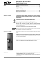
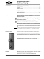
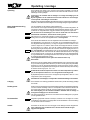
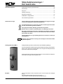
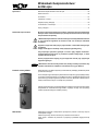
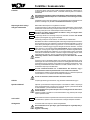
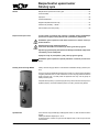
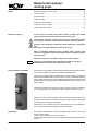
Sicherheitshinweise /
Kurzbeschreibung
Durch den Betrieb des Speichers unter 60°C kann in erheblichem Umfang Energie
eingespart werden.
Ideale Betriebstemperaturen liegen bei 50-60°C.
Wärmeverluste und Verkalkung sind in diesem Bereich wesentlich reduziert.
Hinweis
Inhaltsverzeichnis
Sicherheitshinweise und Kurzbeschreibung .................................................................2
Technische Daten .........................................................................................................3
Verrohrung ....................................................................................................................4
Aufstellung / Montage ...................................................................................................5
Regelung für Ladepumpe ............................................................................................6
Inbetriebnahme - Wartung ............................................................................................7
Durchusswiderstände .................................................................................................8
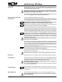
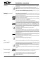
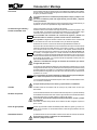
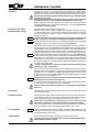
In dieser Beschreibung werden die folgenden Symbole und Hinweiszeichen
verwendet. Diese wichtigen Anweisungen betreffen den Personenschutz und die
technische Betriebssicherheit.
"Sicherheitshinweis" kennzeichnet Anweisungen, die genau einzuhalten sind, um
Gefährdung oder Verletzung von Personen zu vermeiden und Beschädigungen
am Gerät zu verhindern.
Gefahr durch elektrische Spannung an elektrischen Bauteilen!
Achtung: Vor Abnahme der Verkleidung Betriebsschalter ausschalten.
Greifen Sie niemals bei eingeschaltetem Betriebsschalter an elektrische Bauteile
und Kontakte! Es besteht die Gefahr eines Stromschlages mit Gesundheitsge-
fährdung oder Todesfolge.
An Anschlußklemmen liegt auch bei ausgeschaltetem Betriebsschalter Spannung
an.
"Hinweis" kennzeichnet technische Anweisungen, die zu beachten sind, um
Schäden und Funktionsstörungen am Gerät zu verhindern.
Achtung
Sicherheitshinweise
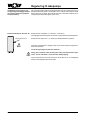
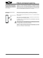
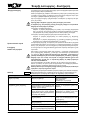
Solarspeicher Typ SEM-2 aus Stahl S235JR mit Gütenachweis (mit seitlichem Flansch).
Korrosionsschutz durch Doppelschicht-Emaillierung von Behälterinnenwand und
Heizschlange nach DIN 4753 Teil 3. Zusätzlicher Korrosionsschutz durch Magnesium-
Schutzanode, bei allen Wasserverhältnissen und in jedem Leitungsnetz einsetzbar.
Optional kann die Solarpumpengruppe aus dem Wolf-Lieferprogramm mit Hilfe des
Anschluss-Sets Solar direkt am Solarspeicher SEM-2 montiert werden.
Solarspeicher SEM-2
2 3062505_201507

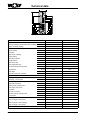
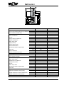
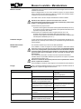
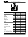
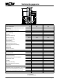
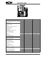
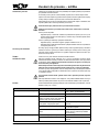
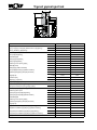
Technische Daten
TYP SEM-2 300 400
Speicherinhalt Ltr. 285 385
Speicherdauerleistung 80/60-10/45°C (Heizung) kW - Ltr./h 20 - 490 20 - 490
Leistungskennzahl (Heizung) NL60 2,3 4,8
Kaltwasseranschluss A mm 90 55
Rücklauf Heizung B mm 974 987
Zirkulation C mm 1077 1092
Speicherfühler Heizung D mm 1154 1204
Vorlauf Heizung E mm 1334 1335
Warmwasseranschluss F mm 1728 1586
Flansch (unten) G mm 324 275
Speicherfühler Solar H mm 506 416
Rück-/Vorlauf Solar I mm 815 874
Elektrozusatzheizung J mm 887 915
Thermometer K mm 1504 1416
Gesamthöhe L mm 1794 1651
Durchmesser mit Wärmedämmung M mm 600 701
Kippmaß mit Wärmedämmung mm 1898 1820
Primär-Heizwasser bar/°C 10/110 10/110
Sekundär-Brauchwasser bar/°C 10/95 10/95
Flanschinnendurchmesser mm 110 110
Kaltwasseranschluss R (AG) 1“ 1“
Heizungsvor-/Heizungsrücklauf G (IG) 1“ 1“
Solarvor-/Solarrücklauf G (IG) ¾“ ¾“
Zirkulation G (IG) ¾“ ¾“ *
Warmwasseranschluss R (AG) 1“ 1“
Elektrozusatzheizung G (IG) 1½“ 1½“
Thermometer G (IG) ½“ ½“
Wärmetauscheräche (Heizung) m² 0,95 0,95
Wärmetauscheräche (Solar) m² 1,3 1,8
Wärmetauscherinhalt (Heizung) Ltr. 6,6 7,0
Wärmetauscherinhalt (Solar) Ltr. 9,0 12,8
Gewicht kg 130 159
B
A
C
D
F
E
K
L
M
I
J
H
G
3062505_201507 3

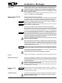
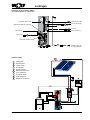
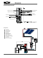
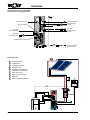
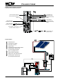
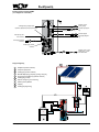
Verrohrung
Anschluß Solarspeicher SEM-2
an Heizkessel und Kollektorfeld
Anlagenschema
1 Kollektorfeld
2 Entlüftungstopf
3 Kollektorfühler
4 Solarmodul
5 Solarpumpenruppe
6 Speicherfühler Solar
7 Füll- und Entleerungshahn
8 Solarspeicher SEM-2
9 Heizkessel
10 Speicherfühler Heizung
Tauchhülse Thermometer
Elektrozusatzheizung
Speicherfühler Solar
Speicherfühler Heizung
Warmwasseranschluß
Heizungsvorlauf
Zirkulation
Heizungsrücklauf
Solarvorlauf
Solarrücklauf
Kaltwasseranschluß
nach DIN 1988
4 3062505_201507

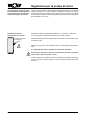
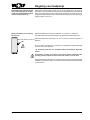
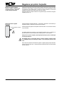
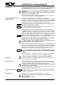
Aufstellung / Montage
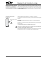
Aufstellung
Der Solarspeicher darf nur in einem frostgeschützten Raum aufgestellt werden, an-
dernfalls muß bei Frostgefahr der Speicher, sowie alle wasserführenden Armaturen
und Anschlußleitungen entleert werden!
Eisbildung in der Anlage kann zu Leckagen und Zerstörung des Speichers führen!
Beim Entleeren der Anlage kann heißes Wasser austreten und Verletzungen,
insbesondere Verbrennungen verursachen!
Der Aufstellungsort muß den notwendigen Raum für Wartung und Reparatur, sowie eine
ausreichende Tragfähigkeit des Untergrundes gewährleisten!
Wärmedämmung
Die Wärmedämmung des Speichers muß vor der Verrohrung angebracht werden!
Feuer, Lötamme bzw. Schweißbrenner nicht in die Nähe der Dämmung bringen.
Achtung: Brandgefahr!
Trinkwasserlter
Da eingeschwemmte Fremdteile Armaturen usw. verstopfen und Korrosion in den Lei-
tungen verursachen, wird empfohlen in der Kaltwasserzuleitung einen Trinkwasserlter
zu installieren.
Achtung
Druckminderer
Der Einbau eines Druckminderventils wird empfohlen. Der zulässige Betriebsdruck des
Solarspeichers beträgt brauchwasserseitig 10 bar. Wird das Versorgungsnetz mit einem
höheren Druck betrieben, muß ein Druckminderer einbaut werden.
Eine Überschreitung des zulässigen Betriebsdruckes kann zu Leckagen und
Zerstörung des Speichers führen!
Zur Verminderung der Fließgeräusche innerhalb von Gebäuden sollte der Leitungsdruck
auf ca. 3,5 bar eingestellt werden.
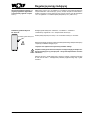
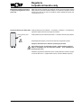
Der Solarspeicher ist so zu installieren, daß er ohne Demontage entleert werden kann.
Entleerung
Warm-/Kaltwasseranschluß
Solarspeicher
Vor der Rohrinstallation Wärmedämmung anbringen.
Der Solarspeicher ist nach dem Verrohrungs-Schema auf Seite 4 anzuschließen. Es darf
nur ein bauteilgeprüftes Sicherheitsventil verwendet werden. Zwischen Solarspeicher
und Sicherheitsventil darf keine Absperreinrichtung eingebaut werden.
Ist der Speicher an den Warm- und Kaltwasseranschlüssen mit nicht metallischen
Rohrwerkstoffen verbunden, so muss der Speicher geerdet werden!
Der Einbau von Schmutzfängern oder anderen Verengungen in die Verbindungsleitung
zwischen Solarspeicher und Sicherheitsventil ist unzulässig.
Der Mindest-Anschlußdurchmesser des Sicherheitsventils muß DN20-¾" betragen.
Die Ausblaseleitung muß mindestens in Größe des Sicherheitsventil-Austrittsquerschnitt
ausgeführt werden, darf höchstens 2 Bögen aufweisen und höchstens 2 m lang sein.
Werden aus zwingenden Gründen 3 Bögen oder eine Länge bis zu 4 m erforderlich,
so muß die gesamte Ausblaseleitung eine Nennweite größer ausgeführt werden. Mehr
als 3 Bögen sowie eine Länge über 4 m sind unzulässig. Die Ausblaseleitung muß mit
Gefälle verlegt sein. Die Ablaueitung hinter dem Ablauftrichter muß mindestens den
doppelten Querschnitt des Ventileintritts aufweisen. In der Nähe der Ausblaseleitung
des Sicherheitsventils, zweckmäßig am Sicherheitsventil selbst, ist ein Hinweisschild
anzubringen mit der Aufschrift:
"Während der Beheizung tritt aus Sicherheitsgründen Wasser aus der Ausblase-
leitung aus! Nicht verschließen!"
Bei der Wahl des anlagenseitigen Installationsmaterials ist auf die Regeln der Technik
sowie auf eventuelle mögliche elektrochemische Vorgänge zu achten (Mischinstalla-
tion)! Der Speicher kann mit einer Elektrozusatzheizung ausgerüstet werden, die mit
einem Sicherheitstemperaturbegrenzer ausgestattet ist. Dieser schaltet im Falle einer
Fehlfunktion die weitere Beheizung bei max. 110° C ab.
Die betreffenden Anschlußkomponenten sind für diese Temperatur auszulegen
oder die Temperatur über ein Mischventil zu begrenzen!
Bei Brauchwassertemperaturen über 60°C wird generell empfohlen, diese über ein
Mischventil auf 60°C zu begrenzen!
Heißes Wasser kann Verletzungen, insbesondere Verbrühungen verursachen!
Achtung
Achtung
Achtung
Achtung
3062505_201507 5

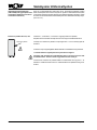
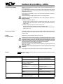
Regelung für Ladepumpe
Elektronischen Speichertemperaturfühler der Heizungsregelung in die obere Tauchhül-
se für Speicherfühler Heizung stecken und mit Fühlerhalter befestigen. Bei Speichern
mit Fühlerkanal, Fühler senkrecht nach unten, bis Anschlag einschieben. Gewünschte
Speichertemperatur am Speichertemperaturregler der Heizungsregelung einstellen.
(max. 60°C).
Witterungsgeführte Heizungsregelung
(Heizungsregelung mit integriertem
Speichertemperaturregler und Spei-
chertemperaturfühler)
Elektrozusatzheizung E2 / E4,5 / E6
Die Vorschriften und Bestimmungen des VDE und der örtlichen Energie-Versorgungs-
unternehmen sind zu beachten.
Der Anschluß muß durch einen konzessionierten Elektroinstallateur erfolgen.
Geräte vor dem Öffnen stromlos machen! Berühren Sie niemals unter Strom
stehende Bauteile - es besteht die Gefahr von Verletzung oder Tod!
Deckel von Elektrozusatzheizung abschrauben und gemäß beiliegender Anleitung an
Netz 230 oder 400 V~ anschließen. Anschlußkabel muß bauseits gestellt werden.
Elektrozusatzheizung 2 kW/230V~, 4,5 kW/400 V~, 6 kW/400 V~.
mit eingebautem Speichertemperaturregler und Sicherheitstemperaturbegrenzer.
Elektrozusatzheizung in die 1 1/2" Muffe am Solarspeicher eindrehen und
abdichten.
Elektrozusatzheizung
6 3062505_201507

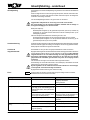
Inbetriebnahme - Wartung
Inbetriebnahme
Die Aufstellung und erste Inbetriebnahme darf nur durch eine anerkannte Installations-
rma erfolgen.
Nach der Montage Rohre und Speicher gründlich durchspülen, Speicher mit Wasser
füllen. Warmwasserzapfhahn öffnen bis Wasser ausläuft und Sicherheitsventil durch
Anlüften überprüfen.
Vor Inbetriebnahme Speicher unbedingt füllen und entlüften!
Achtung: Max. Betriebsdruck von 10 bar darf nicht überschritten werden!
Eine Überschreitung des zulässigen Betriebsdruckes kann zu Leckagen und
Zerstörung des Speichers führen!
Betrieb mit Ladepumpe:
Speichertemperaturregler auf gewünschte Temperatur (max. 60°C) einstellen. Bei
Anschluß eines elektronischen Speicherfühlers wird die Speichertemperatur an der
Kesselregelung eingestellt.
Betrieb mit Elektrozusatzheizung E2 / E4,5 / E6
Speichertemperaturregler der Heizungsregelung auf 20°C einstellen.
Speichertemperaturregler der Elektrozusatzheizung auf gewünschte Temperatur
(max.60°C) drehen.
Frostschutz
Zur Energieeinsparung bei längerer Abwesenheit kann der Speichertemperaturregler
ganz nach links (gegen Uhrzeigersinn) gedreht werden, dabei bleibt die Frostschutz-
funktion erhalten.
Wartung
Magnesiumanode
Die Anlage ist alle 2 Jahre durch eine Fachrma überprüfen zu lassen.
Bei eingebauter Magnesiumanode beruht die Schutzwirkung auf elektrochemischer
Reaktion, die einen Abbau des Magnesiums zur Folge hat. Bei verbrauchter Magne-
siumanode ist der Korrosionsschutz des Speichers nicht mehr gewährleistet!
Folge: Durchrostung, Wasseraustritt. Deshalb muß sie alle 2 Jahre durch einen
konzessionierten Installateur kontrolliert und bei mehr als 2/3 Abnutzung erneuert
werden!
Zum Austausch der Anode muß der Speicher drucklos gemacht werden.
Kaltwasseranschluß schließen, Zirkulationspumpe abschalten und beliebigen Warm-
wasserhahn im Haus öffnen.
Beim Entleeren der Anlage kann heißes Wasser austreten und Verletzungen,
insbesondere Verbrühungen verursachen!
Bei eingebauter Fremdstromanode fällt keine Wartung an.
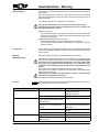
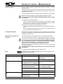
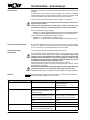
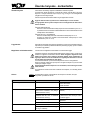
Störung Ursache Behebung
Undichtigkeit am Standspeicher Flansch undicht Schrauben mit 20-25 Nm
kreuzweise nachziehen;
Dichtung auswechseln
Rohranschlüsse undicht Neu eindichten
Aufheizzeit zu lang Heizwasser-Temperatur zu niedrig (am
Vorlauf Standspeicher messen, nicht am
Wärmeerzeuger)
Temperatur erhöhen (Regler einstellen)
Heizwassermenge zu klein (bewirkt große
Spreizung, d.h. Rücklauftemperatur zu
niedrig)
Größere Pumpe
Gegendruck von parallelen Heizungskreis-
lauf beachten
Heizschlange nicht entlüftet Bei abgeschalteter Pumpe mehrmals
entlüften
Verkalkung der Heizäche Heizäche entkalken
Brauchwassertemperatur zu gering Thermostat schaltet zu früh ab Thermostat nachstellen
Rücklauftemperatur zu niedrig (z.B. zu
große Spreizung)
Größere Ladepumpe
Nach Demontage des Flansches muss bei Wiedereinbau die Dichtung erneuert wer-
den, Anzugsdrehmoment der Muttern 20-25 Nm.
Achtung
Flansch
3062505_201507 7

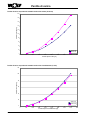
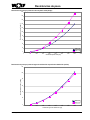
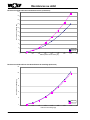
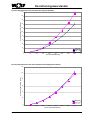
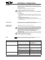
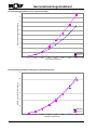
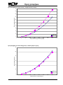
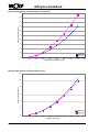
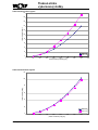
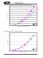
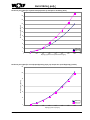
Durchusswiderstände
0
20
40
60
80
100
120
140
160
180
200
0 500 1000 1500 2000 2500 3000 3500 4000 4500
SEM-2-300
SEM-2-400
Durchusswiderstand [mbar]
Solarüssigkeitdurchsatz [l/h]
Solarseitiger Durchusswiderstand Solarwendel (unten)
0
20
40
60
80
100
120
0 500 1000 1500 2000 2500 3000 3500 4000 4500
SEM-2-300
SEM-2-400
Durchusswiderstand [mbar]
Heizwasserdurchsatz [l/h]
Heizwasserseitiger Durchusswiderstand Heizwendel (oben)
8 3062505_201507

Gerdewan Jacobs
Geschäftsführer Technik
Mainburg, 15.07.2015
KONFORMITÄTSERKLÄRUNG
(nach ISO/IEC 17050-1)
Nummer: 3062505
Aussteller: Wolf GmbH
Anschrift: Industriestraße 1, D-84048 Mainburg
Produkt: Solarspeicher SEM-2
Das oben beschriebene Produkt ist konform mit den Anforderungen der folgenden Dokumente:
DIN EN 12897:2006-09
Gemäß den Bestimmungen der folgenden Richtlinien
2009/125/EG (ErP-Richtlinie)
wird das Produkt wie folgt gekennzeichnet:
i. V. Klaus Grabmaier
Produktzulassung
3062505_201507 9

GB
Assembly Instructions
Solar tank SEM-2
Page 10 - 18
Wolf GmbH · Postfach 1380 · D-84048 Mainburg · Tel. +49-8751/74-0 · Fax +49-8751/741600 · Internet: www.wolf-heiztechnik.de

Safety instructions /
Short description
By operating the tank below 60°C, substantial energy savings can be achieved.
Ideal operating temperatures are between 50-60°C.
Heat loss and calcication is substantially reduced in this range.
Note
Table of contents
Safety instructions and short description .................................................................... 11
Technical data.............................................................................................................12
Pipework .....................................................................................................................13
Installation / assembly ................................................................................................14
Controller for charging pump .....................................................................................15
Start-up - Servicing .....................................................................................................16
Flow resistances .........................................................................................................17
The following symbols and signs are used in this description. These important
instructions concern personal safety and technical reliability.
"Safety instructions" identify instructions with which you must exactly comply
to prevent injury and damage to the equipment.
Danger through 'live' electrical components.
Warning: Switch the ON/OFF switch to OFF before removing the casing.
Never touch electrical components or contacts when the ON/OFF switch is in
the ON position. This brings a risk of electrocution, which may result in injury
or death.
The supply terminals are still “live” even when the ON/OFF switch is OFF.
"Information" identies technical instructions which you must observe to prevent
damage and avoid malfunctions.
Warning
Safety instructions
Solar tank type SEM-2 made of steel S235JR with quality certication (with lateral ange).
Corrosion protection by double coat enamelling of the inner surface of the tank and heater
coil in accordance with DIN 4753, part 3. Additional corrosion protection with magnesium
protective anode. Can be used with all water conditions and in any pipe system.
The solar pump assembly from the Wolf range can be optionally mounted directly to
the solar tank SEM-2 with the assistance of a solar connection set.
Solar tank SEM-2
3062505_201507 11

Technical data
TYPE SEM-2 300 400
Tank contents litres 285 385
Continuous storage capacity 80/60-10/45°C (heating) kW - l/h 20 - 490 20 - 490
Output coefcient (heating) NL60 2.3 4.8
Cold water connection A mm 90 55
Return heating B mm 974 987
Circulation C mm 1077 1092
Tank sensor of heating D mm 1154 1204
Supply heating E mm 1334 1335
Hot water connection F mm 1728 1586
Flange (bottom) G mm 324 275
Tank sensor solar H mm 506 416
Solar supply/return line I mm 815 874
Electrical auxiliary heating system J mm 887 915
Thermometer K mm 1504 1416
Total height L mm 1794 1651
Diameter with thermal insulation M mm 600 701
Tilting measure with thermal insulation mm 1898 1820
Primary - heating water bar/°C 10/110 10/110
Secondary - service water bar/°C 10/95 10/95
Internal ange diameter mm 110 110
Cold water connection R (ext. thread) 1“ 1“
Heating supply /heating return G (int. thread) 1“ 1“
Solar supply /solar return G (int. thread) ¾“ ¾“
Circulation G (int. thread) ¾“ ¾“ *
Hot water connection R (ext. thread) 1“ 1“
Electrical auxiliary heating system G (int. thread) 1½“ 1½“
Thermometer G (int. thread) ½“ ½“
Heat exchanger surface (heating) m² 0.95 0.95
Heat exchanger surface (solar) m² 1.3 1.8
Heat exchanger content (heating) litres 6.6 7.0
Heat exchanger content (solar) litres 9.0 12.8
Weight kg 130 159
B
A
C
D
F
E
K
L
M
I
J
H
G
12 3062505_201507

Pipework
Connection solar tank SEM-2
to boiler and collector eld
System diagram
1 Collector eld
2 Air-vent bowl
3 Collector sensor
4 Solar module
5 Solar pump assembly
6 Tank sensor solar
7 Fill and drain valve
8 Solar tank SEM-2
9 Boiler
10 Tank sensor of heating
Immersion sleeve thermometer
Electrical auxiliary heating system
Tank sensor solar
Tank sensor of heating
Hot water connection
Heating supply
Circulation
Heating return
Solar supply
Solar return
Cold water connection
according to DIN 1988
3062505_201507 13

Installation / assembly
Installation
The solar tank may only be installed in a room protected against frost, otherwise the
tank and all water-carrying ttings and connecting lines must be emptied if there is a
danger of frost!
Ice formation in the system can lead to leaks and destruction of the tank!
When emptying the system, hot water may escape and cause injuries, particularly
burns!
The installation site must guarantee the space required for maintenance and repair
work as well as sufcient load-bearing capacity of the base!
Thermal insulation
The thermal insulation of the tank must be installed before laying the pipes!
Keep re, soldering ame and/or torches away from the insulation.
Warning: Danger of re!
Drinking water lter
Since washed-in foreign particles clog up ttings etc. and cause corrosion in the lines,
it is recommended to install a drinking water lter in the cold water inlet.
Warning
Pressure reducer
The installation of a pressure reducing valve is recommended. The permissible operating
pressure of the solar tank on the service water side is 10 bar. If the mains is operated
with a higher pressure, a pressure reducer must be installed.
Exceeding the permissible operating pressure can lead to leaks and destruction
of the tank!
To reduce the ow noises within buildings, the pipe pressure should be set to approx.
3.5 bar.
The solar tank must be installed in such a way that it can be emptied without dismantling.
Drain
Hot/cold water connection
solar tank
Install insulation before installing tubing.
The solar tank must be connected according to the pipework diagram on page 4. Only
a component-tested safety valve may be used. No shut-off system may be installed
between solar tank and safety valve.
If the tank is connected with non-metal pipe materials at the hot and cold water
connections, the tank must be earthed!
The installation of splash guards or other narrowings into the connection pipe between
the solar tank and the safety valve is not permitted.
The minimum connection diameter of the safety valve must be DN20-¾".
The exit pipe must be at least equal in size to the safety valve outlet cross-section, may
have no more than 2 elbows and a maximum length of 2 m. If 3 elbows or a length up to
4 m are absolutely required, then the total exit pipe must be designed one nominal size
larger. The use of more than 3 elbows or a length over 4 m is not permitted. The exit
pipe must be installed with downward gradient. The drain pipe behind the drain funnel
must have at least twice the cross section of the valve entry. In the proximity of the exit
pipe of the safety valve, generally on the safety valve itself, a warning label must be
attached with the following text:
"During heating, water exits from exit pipe for safety reasons!
Do not plug the pipe!"
When selecting the installation material on the system side, attention must be paid to
technical regulations and to any possible electrochemical processes (mixed installation)!
The tank can be equipped with an electrical auxiliary heating system, which is equipped
with a safety temperature limiter. In the event of a malfunction, it cuts off any further
heating at max. 110° C.
The corresponding connection components must be designed for this temperature
or the temperature must be limited via a mixing valve!
At service water temperatures exceeding 60°C, limitation to 60°C via a mixing valve is
generally recommended!
Hot water can lead to injuries, particularly scalding!
Warning
Warning
Warning
Warning
14 3062505_201507

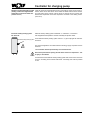
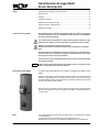
Controller for charging pump
Insert the electronic tank temperature sensor of the heating control into the upper im-
mersion sleeve for the tank sensor of the heater and fasten with the sensor bracket.
For tanks with a sensor channel, push the sensor in vertically as far as it will go. Set
desired tank temperature at the tank temperature controller of the heating control.
(max. 60°C).
Weather-compensated heating control
(heating control with integrated tank
temperature controller and tank tem-
perature sensor)
Electrical auxiliary heating system
E2 / E4.5 / E6
The rules and regulations of the VDE and the local energy supply companies must be
observed.
The connection must be performed by a licensed electrician.
Disconnect power before opening devices! Never touch live components - risk
of injury or even death!
Unscrew the lid of the electrical auxiliary heating system and connect to the mains 230
or 400 V~ according to the enclosed instructions. Connecting wire must be provided
on site.
Electrical auxiliary heating system 2 kW/230V~, 4.5 kW/400 V~, 6 kW/400 V~.
with integrated tank temperature controller and safety temperature limiter.
Screw electrical auxiliary heating system into the 1 ½" pipe coupling at the solar tank
and seal it.
Electrical auxiliary heating system
3062505_201507 15

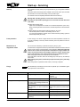
Start-up - Servicing
Start-up
The installation and rst start-up may be performed only by a recognised installation
company.
Flush pipes and tank thoroughly after installation, ll tank with water. Open hot water
tap until water runs out and check safety valve by introducing air.
It is essential to ll and completely bleed tank before the rst start-up!
Warning: Max. operating pressure of 10 bar must not be exceeded!
Exceeding the permissible operating pressure can lead to leaks and destruction
of the tank!
Operation with charging pump:
Adjust the tank temperature controller to the desired temperature (max. 60°C).
When connecting an electronic tank sensor, the tank temperature is set at the boiler
control.
Operation with the electrical auxiliary heating system E2 / E4.5 / E6
Set tank temperature controller of the heating control to 20°C.
Turn the tank temperature controller of the electrical auxiliary heating system to
desired temperature (60°C max).
Frost protection
To save energy in the event of longer absence, the tank temperature controller can
be turned completely to the left (counter-clockwise); the frost protection function is
maintained.
Maintenance of
magnesium anode
The unit must be checked by a professional company every 2 years.
In case of a built-in magnesium anode, the protective effect is based on an electrochemical
reaction, which results in a decomposition of the magnesium. When the magnesium
anode is worn out, the corrosion protection of the tank is no longer ensured! The
result: corrosion perforation, water leakage. Therefore it must be checked every
2 years and replaced in case of more than 2/3 wear by a qualied technician!
When changing the anode, the tank pressure must be relieved.
Close cold water connection, switch off circulating pump and open any hot water tap
in the house.
When emptying the system, hot water may escape and cause injuries, particularly
scalding!
When using a built-in impressed-current anode, no servicing is required.
Fault Cause Remedy
Leakage at oor-standing hot water tank Flange leaking Tighten the screws diagonally with
20-25 Nm;
replace the seal
Pipe connections leaking Re-seal
Heating-up time too long Hot water temperature too low (measure at
the supply of oor-standing hot water tank,
not at the boiler)
Increase temperature (adjust controller)
Heating water amount too small (causes
large spreading, i.e. return temperature
too low)
Larger pump
Observe back pressure of parallel heater
circuit
Heating coil does not bleed Bleed repeatedly with switched-off pump
Calcication of heating surface Decalcify heating surface
Service water temperature too low Thermostat switches off too early Reset thermostat
Return temperature too low (e.g. excessive
spreading)
Larger charging pump
After disassembly of the ange, the seal must be replaced upon re-installation; tighte-
ning torque for the nuts 20-25 Nm.
Warning
Flange
16 3062505_201507

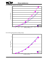
Flow resistances
0
20
40
60
80
100
120
140
160
180
200
0 500 1000 1500 2000 2500 3000 3500 4000 4500
SEM-2-300
SEM-2-400
Flow resistance [mbar]
Solar uid ow rate [l/h]
Flow resistance on solar-side, solar coil (bottom)
0
20
40
60
80
100
120
0 500 1000 1500 2000 2500 3000 3500 4000 4500
SEM-2-300
SEM-2-400
Flow resistance [mbar]
Hot water ow rate [l/h]
Flow resistance heating water side, heating coil (top)
3062505_201507 17

Gerdewan Jacobs
Executive Board Engineering
Mainburg, 15.07.2015
Declaration of conformity
(acc. to ISO/IEC 17050-1)
No.: 3062505
Issued by: Wolf GmbH
Address: Industriestraße 1, D-84048 Mainburg
Product: Solar tank SEM-2
The product described above conforms to the requirements specied in the following documents:
DIN EN 12897:2006-09
In accordance with the following Directives:
2009/125/EG (ErP Directive)
This product is identied as follows:
i. V. Klaus Grabmaier
Product approval
18 3062505_201507

IT
Istruzioni di montaggio
Bollitore solare SEM-2
Pagina 19 - 27
Art.-Nr.: 3062505_201507 Änderungen vorbehalten!
Wolf GmbH · Postfach 1380 · D-84048 Mainburg · Tel. +49-8751/74-0 · Fax +49-8751/741600 · Internet: www.wolf-heiztechnik.de

Indicazioni di sicurezza /
Descrizione breve
Utilizzando il bollitore a temperature inferiori ai 60°C è possibile risparmiare una note-
vole quantità di energia.
Le temperature di esercizio ideali sono comprese tra i 50 e i 60°C.
Le dispersioni termiche e le incrostazioni di calcare si riducono notevolmente con
queste temperature.
Indicazione
Indice
Indicazioni di sicurezza e descrizione breve ..............................................................20
Dati tecnici ..................................................................................................................21
Collegamenti idraulici .................................................................................................22
Installazione / Montaggio ............................................................................................23
Regolazione per la pompa di carico ..........................................................................24
Messa in servizio - Manutenzione ..............................................................................25
Perdite di carico ..........................................................................................................26
In questo manuale vengono utilizzati i seguenti simboli e segnali informativi.
Queste importanti indicazioni riguardano la protezione personale e la sicurezza
di funzionamento.
"Indicazioni di sicurezza" si riferisce ad istruzioni da seguire attentamente per
evitare ferimenti di persone e danneggiamenti all'apparecchio.
Pericolo a causa della tensione elettrica sui componenti elettrici!
Attenzione: Spegnere l'interruttore generale prima di togliere il mantello.
Non toccare mai i componenti ed i contatti elettrici con l'interruttore generale
acceso! Vi è il pericolo di scosse elettriche che possono compromettere la salute
o avere conseguenze mortali.
I morsetti sono alimentati anche con l'interruttore generale spento.
"Avvertenza" indica istruzioni tecniche che devono essere osservate per evitare
danni o problemi di funzionamento all'apparecchio.
Attenzione
Indicazioni di sicurezza
Bollitore solare di tipo SEM-2 in acciaio S235JR con certicato di qualità (dotato di angia
laterale).
Protetto dalla corrosione mediante doppia smaltatura della parete interna del serbatoio
e serpentino di riscaldamento conforme a DIN 4753 parte 3. Ulteriore protezione dalla
corrosione grazie all’anodo di protezione al magnesio, utilizzabile con tutti i tipi di acqua
e ogni tipo di rete di alimentazione.
Facoltativamente il gruppo pompe solari della gamma Wolf può essere montato con
l’ausilio di kit di collegamento solare direttamente al bollitore solare SEM-2.
Bollitore solare SEM-2
20 3062505_201507
Strona się ładuje...
Strona się ładuje...
Strona się ładuje...
Strona się ładuje...
Strona się ładuje...
Strona się ładuje...
Strona się ładuje...
Strona się ładuje...
Strona się ładuje...
Strona się ładuje...
Strona się ładuje...
Strona się ładuje...
Strona się ładuje...
Strona się ładuje...
Strona się ładuje...
Strona się ładuje...
Strona się ładuje...
Strona się ładuje...
Strona się ładuje...
Strona się ładuje...
Strona się ładuje...
Strona się ładuje...
Strona się ładuje...
Strona się ładuje...
Strona się ładuje...
Strona się ładuje...
Strona się ładuje...
Strona się ładuje...
Strona się ładuje...
Strona się ładuje...
Strona się ładuje...
Strona się ładuje...
Strona się ładuje...
Strona się ładuje...
Strona się ładuje...
Strona się ładuje...
Strona się ładuje...
Strona się ładuje...
Strona się ładuje...
Strona się ładuje...
Strona się ładuje...
Strona się ładuje...
Strona się ładuje...
Strona się ładuje...
Strona się ładuje...
Strona się ładuje...
Strona się ładuje...
Strona się ładuje...
Strona się ładuje...
Strona się ładuje...
Strona się ładuje...
Strona się ładuje...
Strona się ładuje...
Strona się ładuje...
Strona się ładuje...
Strona się ładuje...
Strona się ładuje...
Strona się ładuje...
Strona się ładuje...
Strona się ładuje...
Strona się ładuje...
Strona się ładuje...
Strona się ładuje...
Strona się ładuje...
Strona się ładuje...
Strona się ładuje...
Strona się ładuje...
Strona się ładuje...
Strona się ładuje...
Strona się ładuje...
Strona się ładuje...
Strona się ładuje...
Strona się ładuje...
Strona się ładuje...
Strona się ładuje...
Strona się ładuje...
Strona się ładuje...
Strona się ładuje...
Strona się ładuje...
Strona się ładuje...
Strona się ładuje...
Strona się ładuje...
Strona się ładuje...
Strona się ładuje...
Strona się ładuje...
Strona się ładuje...
Strona się ładuje...
Strona się ładuje...
-
 1
1
-
 2
2
-
 3
3
-
 4
4
-
 5
5
-
 6
6
-
 7
7
-
 8
8
-
 9
9
-
 10
10
-
 11
11
-
 12
12
-
 13
13
-
 14
14
-
 15
15
-
 16
16
-
 17
17
-
 18
18
-
 19
19
-
 20
20
-
 21
21
-
 22
22
-
 23
23
-
 24
24
-
 25
25
-
 26
26
-
 27
27
-
 28
28
-
 29
29
-
 30
30
-
 31
31
-
 32
32
-
 33
33
-
 34
34
-
 35
35
-
 36
36
-
 37
37
-
 38
38
-
 39
39
-
 40
40
-
 41
41
-
 42
42
-
 43
43
-
 44
44
-
 45
45
-
 46
46
-
 47
47
-
 48
48
-
 49
49
-
 50
50
-
 51
51
-
 52
52
-
 53
53
-
 54
54
-
 55
55
-
 56
56
-
 57
57
-
 58
58
-
 59
59
-
 60
60
-
 61
61
-
 62
62
-
 63
63
-
 64
64
-
 65
65
-
 66
66
-
 67
67
-
 68
68
-
 69
69
-
 70
70
-
 71
71
-
 72
72
-
 73
73
-
 74
74
-
 75
75
-
 76
76
-
 77
77
-
 78
78
-
 79
79
-
 80
80
-
 81
81
-
 82
82
-
 83
83
-
 84
84
-
 85
85
-
 86
86
-
 87
87
-
 88
88
-
 89
89
-
 90
90
-
 91
91
-
 92
92
-
 93
93
-
 94
94
-
 95
95
-
 96
96
-
 97
97
-
 98
98
-
 99
99
-
 100
100
-
 101
101
-
 102
102
-
 103
103
-
 104
104
-
 105
105
-
 106
106
-
 107
107
-
 108
108


Wolf SEM-2 400 Assembly Instructions Manual
- Typ
- Assembly Instructions Manual
- Niniejsza instrukcja jest również odpowiednia dla
w innych językach
- čeština: Wolf SEM-2 400
- español: Wolf SEM-2 400
- italiano: Wolf SEM-2 400
- Deutsch: Wolf SEM-2 400
- slovenčina: Wolf SEM-2 400
- français: Wolf SEM-2 400
- English: Wolf SEM-2 400
- dansk: Wolf SEM-2 400
- Nederlands: Wolf SEM-2 400
Powiązane artykuły
-
Wolf SEM-1 Assembly Instructions Manual
-
-
-
-
-
-
-
-
Inne dokumenty
-
Siemens DG10036R Instrukcja obsługi
-
Atlantic MILEO / MILEO + Installation and User Manual
-
Gorenje OTG80SLSIMC6 Instrukcja obsługi
-
-
STIEBEL ELTRON SBB 600_1000_WP_SOL Operation Instruction
-
Kospel SE Instrukcja obsługi
-
Panasonic PAWDHWM200ZC Instrukcja obsługi
-
-
-