HF 88105 RE / Stand: 12.2022 / Druck: 12.2022
+ PL HU NO SK
DE Anleitung für Montage und Betrieb
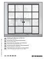
Stahl-Loftschiebetüren
EN Instructions for fitting and operating
Steel loft sliding doors
FR Instructions de montage et d’utilisation
Portes de loft coulissantes en acier
ES Instrucciones de montaje y funcionamiento
Puertas correderas Loft de acero
RU Руководство по монтажу и эксплуатации
Стальные раздвижные двери в стиле «лофт»


1 Zu dieser Anleitung ................................................................................... 4
1.1 Verwendete Warnhinweise .......................................................................... 4
1.2 Verwendete Symbole ..................................................................................4
1.3 Verwendete Abkürzungen ...........................................................................4
2 Lieferumfang .............................................................................................5
2.1 Mitgelieferte Bausätze prüfen ..................................................................... 5
3 Montage ..................................................................................................... 5
3.1 Einbauort prüfen ......................................................................................... 5
3.2 Fachpersonal und Gewährleistung ............................................................. 6
3.3 Montagearten und Befestigungszubehör ................................................... 6
3.4 Einbauvarianten ......................................................................................... 6
3.5 Wandmontage der Laufschiene mit Abstandsprofil....................................7
3.6 Decken- oder Wandtaschenmontage der Laufschiene .............................. 7
3.7 Türaussteller HELM .................................................................................... 7
3.8 Synchronlaufschiene zusammen bauen ..................................................... 7
3.9 Flügel einhängen und ausrichten ................................................................ 8
3.10 Einzugsdämpfer SmartStop 140.................................................................9
3.11 Rollenführung.............................................................................................. 9
3.12 Montagetipps .............................................................................................. 9
3.13 REPLACK - Behälter mit Pinsel und Präzisionsnadel ................................10
4 Pflege und Wartung ................................................................................ 10
Inhaltsverzeichnis
Weitergabe sowie Vervielfältigung dieses Dokuments, Verwertung und Mitteilung seines Inhalts
sind verboten, soweit nicht ausdrücklich gestattet. Zuwiderhandlungen verpflichten zu Scha-
denersatz. Alle Rechte für den Fall der Patent-, Gebrauchsmuster- oder Geschmacksmuster-
eintragung vorbehalten. Änderungen vorbehalten.
HF 88105 RE / 12.2022 3
DEUTSCH

Sehr geehrte Kundin, sehr geehrter Kunde,
wir bedanken uns, dass Sie sich für ein Qualitätsprodukt aus unserem Haus
entschieden haben.
1 Zu dieser Anleitung
Diese Anleitung enthält wichtige Informationen zum Produkt.
▶ Lesen Sie die Anleitung sorgfältig und vollständig.
▶ Beachten Sie alle Hinweise. Befolgen Sie insbesondere die Sicherheitshin-
weise und Warnhinweise.
▶ Bewahren Sie die Anleitung sorgfältig auf.
▶ Vergewissern Sie sich, dass die Anleitung jederzeit verfügbar und für den
Benutzer des Produkts einsehbar ist.
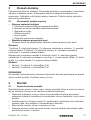
1.1 Verwendete Warnhinweise
Das allgemeine Warnsymbol kennzeichnet eine Gefahr, die zu Verlet-
zungen oder zum Tod führen kann. Im Textteil wird das allgemeine Warnsymbol
in Verbindung mit den nachfolgend beschriebenen Warnstufen verwendet.
ImBildteil verweisen zusätzliche Angaben auf die Erläuterungen im Textteil.
ACHTUNG
Kennzeichnet eine Gefahr, die zur Beschädigung oder Zerstörung des
Produkts führen kann.
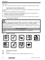
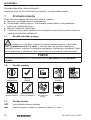
1.2 Verwendete Symbole
wichtiger Hinweis korrektes
Vorgehen werkseitig arbeiten mit
2Personen Verschraubung
fest anziehen
prüfen bauseitiges
Sichern optionale
Bauteile siehe Hersteller-
anleitung
1.3 Verwendete Abkürzungen
OFF Oberkante Fertigfußboden
mm alle Maßangaben im Bildteil in mm
4HF 88105 RE / 12.2022
DEUTSCH

2 Lieferumfang
Prüfen Sie die Lieferung auf Vollständigkeit. Vergleichen Sie die Lieferung mit der
Bestellung, der Auftragsbestätigung und dem Lieferschein. Sorgen Sie für eine
sachgemäße Zwischenlagerung auf der Baustelle. Entfernen und entsorgen Sie
das Verpackungsmaterial. Schützen Sie alle Einzelteile vor Beschädigung.
2.1 Mitgelieferte Bausätze prüfen
• Laufschienen-Bausatz
1 × Aluminium-Laufschiene auf Länge zugeschnitten.
Je nach Montageausführung enthält die Lieferung:
– Adapterprofile
– Abstandsprofile
– Abdeckprofile
– entsprechendes Befestigungsmaterial
• Schiebetürmontageset
Die Lieferung ist abhängig von der bestellten Schiebetür-
Ausstattungsvariante.
Standard
1-flüglig: 2 × Fangstopper, 2 × Rollapparat mit Flansch, 1 × untere Führungsrolle
2-flüglig: 4 × Fangstopper, 4 × Rollapparat mit Flansch, 2 × untere Führungsrolle
Synchronset 2-flüglig: 4 × Fangstopper, 4 × Rollapparat mit Flansch,
1 ×Antriebsriemen (Länge = 2 × Flügelbreite), 2 × Umlenkrolle, 2 × untere
Führungsrolle
Option
• Variante: 1-flüglig, 2 × SmartStop140
• Variante: 2-flüglig, 4 × SmartStop140
HINWEIS
Für die Anschraubmontage mit Gewindeschrauben benötigen Sie bauseitige
Stahlprofile mit einer Wandstärke ≥ 4mm.
3 Montage
3.1 Einbauort prüfen
Prüfen Sie die Beschaffenheit der Wandöffnung bzw. des Einbauorts. Die Türen
und Elemente sind nur für den Innenbereich bestimmt. Die Türen sind nicht für
die statische Lastannahme geeignet.
• Die Beschaffenheit und die Abmessungen der Wandöffnung müssen eine
kraftschlüssige Befestigung durch geeignete Montagemittel wie Dübel, Anker
oder Schrauben ermöglichen.
• Der Boden muss tragfähig und eben sein. Planen Sie bei Verglasungen immer
eine Verankerung nach unten gegen horizontales Verrutschen.
• Prüfung Sie die Öffnungsmaße und die Elementmaße.
HF 88105 RE / 12.2022 5
DEUTSCH

• Übertragen Sie den Meterriss am Rohbau zur richtigen Höheneinordnung des
Elements im Objekt.
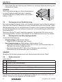
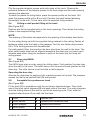
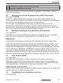
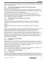
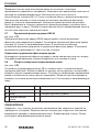
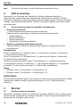
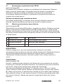
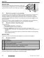
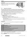
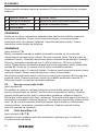
HINWEIS
Die Anschraubmontage mit Gewindeschrauben
an eine Gipskartonwand erfordert bauseitig
Leichtbauwände mit Stahlprofilen einer Wand-
stärke ≥ 4mm.
50×50
≥ 4
3.2 Fachpersonal und Gewährleistung
Nur sachkundige Personen dürfen die Produkte einbauen und in Betrieb nehmen.
Hersteller und Lieferant übernehmen keine Gewährleistung für den Einbau. Diese
Montageanleitung hat nur empfehlenden Charakter, da es mehrere Möglichkeiten
für den fachgerechten und richtigen Einbau gibt. Auf Empfehlungen besteht kein
Rechtsanspruch.
Montieren Sie die Tür nach Herstellervorgaben. Vergewissern Sie sich von der
ordnungsgemäßen Funktion. Erst danach ist die Inbetriebnahme der Tür erlaubt.
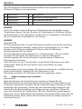
3.3 Montagearten und Befestigungszubehör
Laufschienenbefestigung:
• Dübelmontage in Mauerwerk, Beton
– Dübel 8 × 65S Duopower von Fischer
• Anschraubmontage an Stahlträgern, Mindestdicke 4mm
– gewindefurchende Schrauben GEFU M5 × 50 mit zylindrischem Kopf zur
Montage des oberen Rahmenprofils
– Senkkopfschraube GEFU M6 × 50 zur Montage des seitlichen
Rahmenprofils der Seitenteile (falls vorhanden.)
HINWEIS
Beachten Sie Mindestrandabstand und Mindesteinbindetiefe der Dübel.
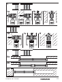
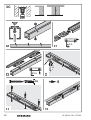
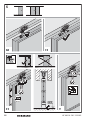
3.4 Einbauvarianten
(sieheBild1)
1a Wandmontage
1b Decken- bzw. Sturzmontage
1c Wandtaschenmontage
1d Wandmontage synchron (nur bei 2-flügliger Schiebetür)
1e Decken- bzw. Sturzmontage synchron
1f Wandtaschenmontage synchron
Entnehmen und prüfen Sie den mitgelieferten Bausatz der Laufschiene 140 von
Woelm. Prüfen Sie den Bausatz auf Vollständigkeit.
6HF 88105 RE / 12.2022
DEUTSCH

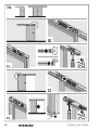
3.5 Wandmontage der Laufschiene mit Abstandsprofil
(sieheBild3A/3B)
Klipsen Sie die mitgelieferten Adapterstücke beidseitig an das Schienenprofil.
Berücksichtigen Sie den angegebenen Abstand der Adapterstücke zum
Schienenrand und die inneren Abstände zwischen den Adaptern.
Um die Stellen für die Befestigungsbohrungen zu markieren, legen Sie das
Abstandsprofil an die Laufscheine. Bohren Sie das Abstandsprofil mit einem
Bohrer 8mm auf. Positionieren Sie die Laufschiene vor dem Befestigen
waagrecht an der Wand. Befestigen Sie die Schiene mit dem mitgelieferten
Befestigungsmaterial.
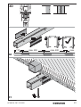
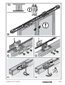
3.6 Decken- oder Wandtaschenmontage der Laufschiene
(sieheBild3C)
Positionieren und befestigen Sie die mitgelieferten Bolzen in den Öffnungen der
Laufschiene. Befestigen Sie anschließend die Deckenplatten in der mitgelieferten
Deckenschiene.
HINWEIS
Der Abstand der Platten entspricht der Aufteilung der bereits befestigten Bolzen.
Fixieren Sie die Deckenbefestigungsschiene mit dem mitgelieferten
Befestigungsmaterial an der Decke. Befestigen Sie alle Befestigungsplatten im
Durchgang an der Laufschiene. Benutzen Sie dafür Linsenkopfschrauben M4 × 10
oder Sperrschrauben mit Schraubensicherung.
Bei der Wandtaschenmontage positionieren Sie den Türaussteller zuerst (von der
Wand aus) in der Laufschiene. Die Fanghaken der Rollen dürfen nicht Richtung
Türaussteller ausgerichtet sein, sondern müssen zueinander zeigen. Hängen Sie
die eingeschraubten Bolzen der Laufschiene in die Deckenplatten der
Befestigungsschiene.
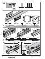
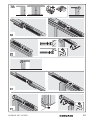
3.7 Türaussteller HELM
(sieheBild4C)
Der Türaussteller HELM ist eine Ausstellfeder für Schiebetüren. Positionieren Sie
den Türaussteller zuerst (von der Wand aus) in der Laufschiene. Der Rollapparat
liegt in der Endlage am Türaussteller an. Der Rollapparat wird nicht gehalten, wie
bei einem Fangstopper.
Türausteller bedienen
Aktivieren Sie den Türaussteller mit leichtem manuellen Druck auf den Flügel. Der
Druck bewirkt die Ausstellung des Flügels aus der Wandtasche.
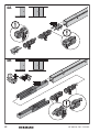
3.8 Synchronlaufschiene zusammen bauen
(sieheBild4D)
Montieren Sie die Laufschiene (1) entsprechend den zuvor beschriebenen
Schritten. Schieben Sie dann einen der inneren Fangstopper (3) in jede Seite der
Laufschiene. Die Fangstopper stoppen die Schiebetüren am Anfang oder Ende
HF 88105 RE / 12.2022 7
DEUTSCH

des Öffnungszyklus. Schieben Sie anschließend die mitgelieferten Rollapparate
(2Stück pro Flügel) in die Laufschiene.
1Laufschiene 5Zahnriemen
2Rollapparat 6Zahnriemen-Verbinderplatte
3Fangstopper 7Zahnriemenmitnehmer
4Umlenkrolle
HINWEIS
Achten Sie darauf, dass die Seiten der Rollapparate ohne Fanghaken zu den
Fangstoppern zeigen. Stecken Sie dann die Fangstopper für die offene Stellung
der Schiebetüren in die Laufschiene. Fixieren Sie die Fangstopper. Positionieren
Sie die Umlenkrollen anschließend in der Schiene.
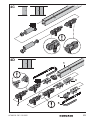
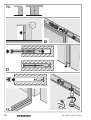
HINWEIS
(sieheBild7D)
Die Zahnriemenverbinder und der Zahnriemenmitnehmer sind bereits werkseitig
an den Schiebeflügeln befestigt. Hängen Sie die Schiebeflügel ein. Für diese
Arbeiten sind 2 Personen erforderlich. Entfernen Sie die Zahnriemen-
Verbindungsplatte (6) vom Winkel.
Die Zahnriemenabmessung beträgt ca. 2 × Schienenlänge + 120mm je Seite.
Verbinden Sie die Enden der Zahnriemen mit Hilfe der Zahnriemen-
Verbindungsplatte (6). Achten Sie darauf, dass Sie jeweils 6 Zähne des
Zahnriemens einklemmen.
Lösen Sie jetzt eine der 2 Umlenkrollen. Legen Sie den Zahnriemen um beide
Umlenkrollen. Spannen Sie den Riemen durch Verschieben der losen
Umlenkrolle.
Um die beiden inneren Fangstopper (3) korrekt zu positionieren, schließen Sie die
beiden Schiebeflügel. Klemmen Sie den Zahnriemen in den
Zahnriemenmitnehmer (7). Positionieren Sie die Fangstopper erneut.
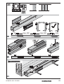
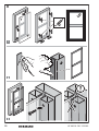
3.9 Flügel einhängen und ausrichten
(sieheBild5)
Nach der Montage und Ausstattung der Laufschiene hängen Sie die
Schiebetürflügel in die werkseitig montierten Flansche. Für diese Arbeiten sind
2Personen erforderlich. Verbinden Sie den Schiebetürflügel vorsichtig mit dem
Rollapparat der Laufschiene. Richten Sie den Schiebetürflügel waagrecht aus.
Fixieren Sie den Schiebetürflügel am Rollapparat der Laufschiene. Prüfen Sie
nach dem Ausrichten die Flügelposition. Bei einer Spaltbildung (geschlossene
Flügel) oder einem Höhenunterschied zwischen den beiden Flügeln führen Sie die
Ausrichtung erneut durch. Ziehen Sie die Kontermuttern der Tragschrauben an
den Flanschen fest.
8HF 88105 RE / 12.2022
DEUTSCH

3.10 Einzugsdämpfer SmartStop 140
(sieheBild4B/7B)
Sie können die Einzugsdämpfereinheit als Zusatzausstattung bei 1-flügligen und
2-flg. Schiebetüren verwenden.
Der SmartStop
– stoppt den Türflügel lautlos und ohne Rückstoß vor dem Erreichen der
Endposition,
– zieht den Türflügel ohne Kraftaufwand in die Endlage und
– hält den Türflügel dort fest.
1. Befestigen Sie die Laufschiene an der Wand.
2. Schieben Sie die Rollapparate zusammen mit den Tragschrauben in die Lauf-
schiene. Sorgen Sie dafür, dass die Fanghaken der Rollen Richtung Smart-
Stop-Dämpfersystems zeigen.
3. Schieben Sie die SmartStop-Einheit jeweils in das Ende der Laufschiene.
Befestigen Sie die SmartStop-Einheit dort mit dem Inbusschlüssel. Spannen
Sie anschließend den Einzugsdämpfer. Schieben Sie hierzu die Mitnehmer-
gabel mit einem Schraubendreher in die Endlage. Die Mitnehmergabel muss
in der Vertiefung einrasten. Spannen Sie das Einzugsdämpfersystem Smart-
Stop während der Montage nur im eingebauten Zustand in der Laufschiene.
3.11 Rollenführung
(sieheBild6)
Damit der Schiebeflügel sanft und stabil gleitet, müssen Sie zusätzlich eine
Rollenführung montieren. Gemäß der Bestellung erhalten Sie eine Rollenführung
für die Bodenmontage (a) oder eine Rollenführung für Wandmontage (b).
Die Lieferung enthält jeweils eine Führungsrolle pro Flügel. Die Montage erfolgt
mit 2 mitgelieferten Montageschrauben.
3.12 Montagetipps
▶ Um Beschädigungen des Kunststoffschaumbands und der
Oberflächenbeschichtung zu vermeiden, lassen Sie beim Verglasen und
Einsetzen des Rahmens Vorsicht walten.
▶ Verwenden Sie beim Montieren der Glashalteleisten geeignetes Werkzeug
T25Bit. Um eine Gewindebeschädigung oder Lackabsplitterungen der
Befestigungsschrauben zu vermeiden, verwenden Sie eine handfeste
Einstellung des Akkuschraubers.
▶ Um die mitgelieferte Verklotzung während des Verglasens der Seitenteile
gegen Verrutschen oder Herausfallen zu sichern, benutzen Sie schwarzes
Silikon.
HF 88105 RE / 12.2022 9
DEUTSCH

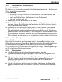
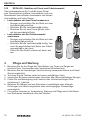
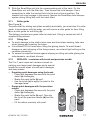
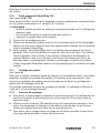
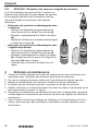
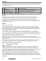
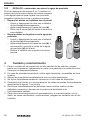
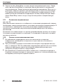
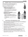
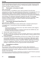
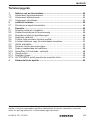
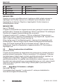
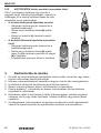
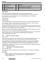
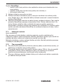
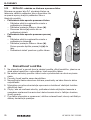
3.13 REPLACK - Behälter mit Pinsel und Präzisionsnadel
Das Lackreparaturset 2in1 enthält einem Pinsel
zum Überstreichen größerer Lackschäden und eine
Spezialnadel zum präzisen Ausbessern von kleinen
Lackschäden und tiefen Rissen.
• Lackschäden mit dem Pinsel ausbessern
– Reinigen und entfetten Sie die Stelle mit dem
Lackdefekt (a) gründlich.
– Schütteln Sie die Lackflasche (b) kräftig.
– Streichen Sie mit dem Pinsel (c) den Lack
auf die beschädigte Stelle.
• Lackschäden mit der Präzisionsnadel
ausbessern
– Reinigen und entfetten Sie die Stelle mit dem
Lackdefekt (a) gründlich.
– Schütteln Sie die Lackflasche (b) kräftig. Tau-
chen Sie anschließend die Spitze der Präzisi-
onsnadel (d) in den Lack.
– Füllen Sie den Defekt präzise mit dem Lack
aus.
bb
aa
d
d
c
c
4 Pflege und Wartung
1. Benutzen Sie für die Pflege der Oberflächen von Türen und Zargen ein
feuchtes Tuch, Fensterleder oder fusselfreies Mikrofasertuch.
2. Benutzen Sie bei hartnäckiger Verschmutzung lauwarmes Wasser und Hand-
Geschirrspülmittel.
3. Trocknen Sie die Flächen sofort mit einem saugfähigen Tuch.
4. Verwenden Sie keine scheuernden, ätzenden oder lösemittelhaltigen Reiniger.
5. Prüfen Sie die Befestigung und Funktion aller funktionswichtigen Teile
mindestens 1 × jährlich.
6. Beheben Sie Mängel wie lose Schrauben, beschädigte oder fehlende
Dichtungen und falsch eingestellte oder schwergängige Türbeschläge
unverzüglich.
7. Für weitere Hinweise zu Verarbeitung, Wartung und Pflege sowie Zertifikate
und Nachweise kontaktieren Sie den Händler.
10 HF 88105 RE / 12.2022
DEUTSCH

1 About these instructions ........................................................................ 12
1.1 Warnings used .......................................................................................... 12
1.2 Symbols used ........................................................................................... 12
1.3 Abbreviations used ................................................................................... 12
2 Scope of delivery .................................................................................... 13
2.1 Check supplied kits .................................................................................. 13
3 Fitting ....................................................................................................... 13
3.1 Check the fitting location .......................................................................... 13
3.2 Qualified personnel and warranty ............................................................. 14
3.3 Fitting types and fitting accessories ......................................................... 14
3.4 Fitting variants ......................................................................................... 14
3.5 Wall fitting of track with spacer profile .....................................................14
3.6 Ceiling or wall pocket fitting of the track .................................................. 15
3.7 Door stay HELM ....................................................................................... 15
3.8 Assemble the synchronous track .............................................................15
3.9 Suspend and align the leaves ................................................................... 16
3.10 Lintel damper SmartStop 140...................................................................16
3.11 Roller guide ............................................................................................... 17
3.12 Fitting tips ................................................................................................. 17
3.13 REPLACK–container with brush and precision needle ...........................17
4 Care and maintenance ...........................................................................18
Contents
Dissemination as well as duplication of this document and the use and communication of its
content are prohibited unless explicitly permitted. Noncompliance will result in damage com-
pensation obligations. All rights reserved in the event of patent, utility model or design model
registration. Subject to changes.
HF 88105 RE / 12.2022 11
ENGLISH

Dear Customer,
We thank you for choosing a quality product from our company.
1 About these instructions
These instructions contain important information on the product.
▶ Read through all of the instructions carefully.
▶ Observe all notes. Please pay particular attention to the safety instructions
and warnings.
▶ Keep these instructions in a safe place for later reference.
▶ Make sure that these instructions are available to the user of the product at all
times.
1.1 Warnings used
The general warning symbol indicates a danger that can lead to injury
or death. In the text, the general warning symbol will be used in connection with
the caution levels described below. In the illustrated section, additional instruc-
tions refer back to the explanation in the text section.
ATTENTION
Indicates a danger that can lead to damage or destruction of the product.
1.2 Symbols used
Important note Correct
procedure At the factory 2 people for work Check
Tighten the screw
fitting firmly On-site
securing Optional
components See
manufacturer’s
instructions
1.3 Abbreviations used
OFF Finished floor level (FFL)
mm All dimensions in the illustrated section are in mm
12 HF 88105 RE / 12.2022
ENGLISH

2 Scope of delivery
Check the delivery for completeness. Compare the delivery with the order, order
confirmation and delivery note. Ensure proper temporary storage at the
construction site. Remove and dispose of the packaging material. Protect all
individual parts from damage.
2.1 Check supplied kits
• Track kit
1 × aluminium track cut to length.
Depending on the fitting version, the delivery includes the following:
– Adapter profiles
– Spacer profiles
– Cover profiles
– Corresponding fixing material
• Sliding door fitting set
The delivery depends on the ordered sliding door equipment variant.
Standard
Single-leaf: 2 × catch stoppers, 2 × roller devices with flange, 1 × bottom guide
roller double-leaf: 4 × catch stoppers, 4 × roller devices with flange, 2 × bottom
guide rollers
Double-leaf synchronous set: 4 × catch stoppers, 4 × roller devices with flange,
1 ×drive belt (length = 2 × leaf width), 2 × return pulleys, 2 × bottom guide rollers
Optional
• Variant: single-leaf, 2 × SmartStop140
• Variant: double-leaf, 4 × SmartStop140
NOTE
For screw fixing with threaded bolts, you need on-site steel profiles with a wall
thickness of ≥ 4mm.
3 Fitting
3.1 Check the fitting location
Check the state of the wall opening / fitting location. The doors and elements are
intended for interior use only. The doors are not suitable for static loads.
• The state and dimensions of the wall opening must enable friction-locked
fastening using suitable fixing materials such as plugs, anchors or screws.
• The floor must be viable and level. For glazing, always plan for downward
fixing to prevent the glazing from sliding horizontally.
• Check the opening dimensions and element dimensions.
• Transfer the metre line on the shell to the correct height of the element in the
construction project.
HF 88105 RE / 12.2022 13
ENGLISH

NOTE
For screw fixing with threaded bolts on a gypsum
board wall, you need on-site partition walls with
steel profiles with a wall thickness of ≥ 4mm.
50×50
≥ 4
3.2 Qualified personnel and warranty
Only specialists may fit and put the products into operation. The manufacturer
and supplier assume no warranty for installation. These fitting instructions only
provide recommendations, as there are several possibilities for professional and
correct fitting. There is no legal claim to recommendations.
Fit the door according to the manufacturer’s instructions. Check for correct
function. Initial start-up of the door is only allowed afterwards.
3.3 Fitting types and fitting accessories
Vertical track fastening:
• Plug-and-screw fitting in brickwork, concrete
– Plugs 8 × 65S Duopower from Fischer
• Screw fixing to steel girders, minimum thickness 4mm
– Self-tapping screws GEFU M5 × 50 with cylindrical head for fitting the top
frame profile
– Countersunk head screw GEFU M6 × 50 for fitting the side frame profile of
the side elements (if available.)
NOTE
Note the minimum edge spacing and minimum anchoring depth of the plugs.
3.4 Fitting variants
(seeFigure1)
1a Wall fitting
1b Ceiling or lintel fitting
1c Wall pocket fitting
1D Synchronous wall fitting (only for double-leaf sliding door)
1e Synchronous ceiling or lintel fitting
1f Synchronous wall pocket fitting
Remove and check the supplied track kit 140 from Woelm. Check the kit for
completeness.
3.5 Wall fitting of track with spacer profile
(See Figure3A/3B)
14 HF 88105 RE / 12.2022
ENGLISH

Clip the supplied adapter pieces onto both sides of the track. Observe the
specified distance of the adapter pieces to the track edge and the inner spacing
between the adapters.
To mark the places for fixing holes, place the spacer profile on the track. Drill
open the spacer profile with a 8mm drill. Position the track before fastening
horizontally to the wall. Fix the track with the supplied fixing material.
3.6 Ceiling or wall pocket fitting of the track
(See Figure3C)
Position and fix the supplied bolts in the track openings. Then fasten the ceiling
plates in the supplied ceiling track.
NOTE
The spacing of the plates corresponds to the spacing of the already fixed bolts.
Fix the ceiling fixing rail with the supplied fixing material to the ceiling. Fasten all
fastening plates onto the track in the passage. For this, use tallow-drop screws
M4 × 10 or locking screws with threadlocker.
For wall pocket fitting, first position the door stay (from the wall) in the track. The
roller catch hooks must not be aligned towards to the door stay, but must point
towards each other. Hang the screwed-in bolts of the track into the fixing rail
ceiling plates.
3.7 Door stay HELM
(See Figure4C)
The HELM door stay is a stay spring for sliding doors. First position the door stay
(from the wall) in the track. The roller device is in the end-of-travel position on the
door stay. The roller device is not held like a catch stopper.
Operating the door stay
Activate the door stay by applying light manual pressure to the leaf. The pressure
causes the leaf to be pushed from the wall pocket.
3.8 Assemble the synchronous track
(See Figure4D)
Fit the track (1) in accordance with the previously described steps. Then slide
one of the inner catch stoppers (3) into each side of the track. The catch stoppers
stop the sliding doors at the start or end of the opening cycle. Then slide the
supplied roller devices (2 per leaf) into the track.
1Track 5toothed belt
2Roller device 6Toothed belt connector plate
3Catch stopper 7Toothed belt bracket
4return pulley
HF 88105 RE / 12.2022 15
ENGLISH

NOTE
Make sure that the sides of the roller devices without catch hooks point towards
the catch stoppers. Then insert the catch stoppers for the open position of the
sliding doors in the track. Fix the catch stoppers. Then position the return pulleys
in the track.
NOTE
(See Figure7D)
The toothed belt connectors and the toothed belt brackets are already fastened
to the sliding leaves in the factory. Hang in the sliding leaves. This work requires
2 people. Remove the toothed belt connection plate (6) from the bracket.
The toothed belt dimensions are approx. 2 × track length + 120mm per side.
Connect the ends of the toothed belts with the aid of the toothed belt connection
plate (6). Make sure that 6 teeth of the toothed belt are clamped at each end.
Now release one of the 2 return pulleys. Place the toothed belt around both
return pulleys. Tension the belt by sliding the loose return pulley.
To position the two inner catch stoppers (3) correctly, close both sliding leaves.
Clamp the toothed belt in the toothed belt bracket (7). Re-position the catch
stoppers.
3.9 Suspend and align the leaves
(See Figure5)
After fitting and equipping the track, hang the sliding door leaves into the flanges
fitted in the factory. 2 people are required for this work. Connect the sliding door
leaf carefully to the track roller device. Align the sliding door leaf horizontally. Fix
the sliding door leaf to the track roller device. Check the alignment of the leaf
position. If there is a gap (closed leaves) or a difference in height between the two
leaves, carry out the alignment again. Tighten the support screw counternuts on
the flanges.
3.10 Lintel damper SmartStop 140
(See Figure4B/7B)
You can use the lintel damper unit as an optional extra for single-leaf and double-
leaf sliding doors.
The SmartStop
– stops the door leaf silently and without rebound prior to reaching the end-
of-travel position,
– pulls the door leaf into the end-of-travel position without force and
– holds the door leaf in position.
1. Fasten the track to the wall.
2. Slide the roller devices together with the support screws into the track. Make
sure that the roller catch hooks point towards the SmartStop damper system.
16 HF 88105 RE / 12.2022
ENGLISH

3. Slide the SmartStop unit into the corresponding end of the track. Fix the
SmartStop unit with the Allen key. Then tension the lintel damper. Use a
screwdriver to slide the bracket fork into the end-of-travel position. The
bracket fork must engage in the recess. Tension the SmartStop lintel damper
system during fitting only with the track fitted.
3.11 Roller guide
(See Figure6)
To ensure that the sliding leaf glides smoothly and stably, you must also fit a roller
guide. In accordance with the order, you will receive a roller guide for floor fitting
(a) or a roller guide for wall fitting (b).
The delivery contains one guide roller for each leaf. Fitting is carried out with 2
supplied fitting screws.
3.12 Fitting tips
▶ To avoid damage to the plastic foam tape and the surface coating, take care
when glazing and inserting the frame.
▶ Use suitable T25bit tools when fitting the glazing beads. To avoid thread
damage or paint chipping of the fixing screws, use a hand-tight setting on the
cordless screwdriver.
▶ To secure the supplied blocks against slipping or falling out while glazing the
side elements, use black silicone.
3.13 REPLACK–container with brush and precision needle
The 2-in-1 paint repair set contains a brush for
painting over larger paint damages and a special
needle for precise repair of small paint damages
and deep cracks.
• Repairing paint damages using the brush
– Clean and degrease the area with the paint
defect (a) thoroughly.
– Shake the paint bottle (b) well.
– Use the brush (c) to apply the paint to the
damaged area.
• Repair paint damages with the precision
needle
– Clean and degrease the area with the paint
defect (a) thoroughly.
– Shake the paint bottle (b) well. Then dip
the tip of the precision needle (d) into the
paint.
– Fill the defect precisely with paint.
bb
aa
d
d
c
c
HF 88105 RE / 12.2022 17
ENGLISH

4 Care and maintenance
1. To maintain the surfaces of doors and frames, use a damp cloth, chamois or a
lint-free microfibre cloth.
2. For stubborn dirt, use lukewarm water and washing-up liquid.
3. Dry the surface immediately with an absorbent piece of cloth.
4. Do not use abrasive, corrosive or solvent-based cleaners.
5. Check the fastening and function of all functionally important parts at least 1 ×
annually.
6. Address defects such as loose screws, damaged or missing seals, incorrectly
set or sluggish door fittings immediately.
7. For additional notes on processing, maintenance and care as well as certific-
ates and verifications, contact your dealer.
18 HF 88105 RE / 12.2022
ENGLISH

1 A propos de ces instructions .................................................................20
1.1 Avertissements utilisés .............................................................................20
1.2 Symboles utilisés ...................................................................................... 20
1.3 Abréviations utilisées ................................................................................ 20
2 matériel livré ............................................................................................21
2.1 Contrôle des kits fournis ........................................................................... 21
3 Montage ................................................................................................... 21
3.1 Contrôle de l’emplacement de montage .................................................. 21
3.2 Personnel qualifié et garantie ................................................................... 22
3.3 Types de montage et accessoires de fixation .......................................... 22
3.4 Variantes de montage .............................................................................. 22
3.5 Montage mural du rail de guidage avec profilé d’écartement .................. 23
3.6 Montage à galandage ou au plafond du rail de guidage .......................... 23
3.7 Arrêt de porte HELM ................................................................................. 23
3.8 Assemblage du rail de guidage synchrone ...............................................24
3.9 Gondage et alignement des vantaux ........................................................ 24
3.10 Arrêt progressif SmartStop 140 ................................................................ 25
3.11 Guidage des galets ................................................................................... 25
3.12 Astuces de montage ................................................................................. 26
3.13 REPLACK - Récipient avec pinceau et aiguille de précision .....................26
4 Entretien et maintenance .......................................................................26
Table des matières
Toute transmission ou reproduction de ce document, toute exploitation ou communication de
son contenu sont interdites, sauf autorisation expresse. Tout manquement à cette règle est illi-
cite et expose son auteur au versement de dommages et intérêts. Tous droits réservés en cas
de dépôt d’un brevet, d’un modèle d’utilité ou d’agrément. Sous réserve de modifications.
HF 88105 RE / 12.2022 19
FRANÇAIS

Cher client,
Nous vous remercions d’avoir opté pour un produit de qualité de notre société.
1 A propos de ces instructions
Les présentes instructions contiennent d’importantes informations concernant ce
produit.
▶ Veuillez les lire intégralement et attentivement.
▶ Respectez toutes les instructions. Respectez notamment l’ensemble des
consignes de sécurité et des avertissements.
▶ Conservez soigneusement les instructions.
▶ Assurez-vous que tous les utilisateurs peuvent les consulter à tout moment.
1.1 Avertissements utilisés
Ce symbole général d’avertissement désigne un danger susceptible de
causer des blessures ou la mort. Dans la partie texte, le symbole général
d’avertissement est utilisé en association avec les degrés de danger décrits ci-
dessous. Dans la partie illustrée, des indications supplémentaires renvoient aux
explications du texte.
AVERTISSEMENT
Désigne un danger susceptible d’endommager ou de détruire le
produit.
1.2 Symboles utilisés
Remarque impor-
tante Procédure
correcte En usine Travailler à 2 Serrage des vis à
fond
Vérification Sécurisation par
l’utilisateur Composants
optionnels Voir instructions
du fabricant
1.3 Abréviations utilisées
OFF Sol fini
mm Toutes les dimensions dans la partie illustrée sont en mm
20 HF 88105 RE / 12.2022
FRANÇAIS
Strona się ładuje...
Strona się ładuje...
Strona się ładuje...
Strona się ładuje...
Strona się ładuje...
Strona się ładuje...
Strona się ładuje...
Strona się ładuje...
Strona się ładuje...
Strona się ładuje...
Strona się ładuje...
Strona się ładuje...
Strona się ładuje...
Strona się ładuje...
Strona się ładuje...
Strona się ładuje...
Strona się ładuje...
Strona się ładuje...
Strona się ładuje...
Strona się ładuje...
Strona się ładuje...
Strona się ładuje...
Strona się ładuje...
Strona się ładuje...
Strona się ładuje...
Strona się ładuje...
Strona się ładuje...
Strona się ładuje...
Strona się ładuje...
Strona się ładuje...
Strona się ładuje...
Strona się ładuje...
Strona się ładuje...
Strona się ładuje...
Strona się ładuje...
Strona się ładuje...
Strona się ładuje...
Strona się ładuje...
Strona się ładuje...
Strona się ładuje...
Strona się ładuje...
Strona się ładuje...
Strona się ładuje...
Strona się ładuje...
Strona się ładuje...
Strona się ładuje...
Strona się ładuje...
Strona się ładuje...
Strona się ładuje...
Strona się ładuje...
Strona się ładuje...
Strona się ładuje...
Strona się ładuje...
Strona się ładuje...
Strona się ładuje...
Strona się ładuje...
Strona się ładuje...
Strona się ładuje...
Strona się ładuje...
Strona się ładuje...
Strona się ładuje...
Strona się ładuje...
Strona się ładuje...
Strona się ładuje...
Strona się ładuje...
Strona się ładuje...
Strona się ładuje...
Strona się ładuje...
Strona się ładuje...
Strona się ładuje...
Strona się ładuje...
Strona się ładuje...
-
 1
1
-
 2
2
-
 3
3
-
 4
4
-
 5
5
-
 6
6
-
 7
7
-
 8
8
-
 9
9
-
 10
10
-
 11
11
-
 12
12
-
 13
13
-
 14
14
-
 15
15
-
 16
16
-
 17
17
-
 18
18
-
 19
19
-
 20
20
-
 21
21
-
 22
22
-
 23
23
-
 24
24
-
 25
25
-
 26
26
-
 27
27
-
 28
28
-
 29
29
-
 30
30
-
 31
31
-
 32
32
-
 33
33
-
 34
34
-
 35
35
-
 36
36
-
 37
37
-
 38
38
-
 39
39
-
 40
40
-
 41
41
-
 42
42
-
 43
43
-
 44
44
-
 45
45
-
 46
46
-
 47
47
-
 48
48
-
 49
49
-
 50
50
-
 51
51
-
 52
52
-
 53
53
-
 54
54
-
 55
55
-
 56
56
-
 57
57
-
 58
58
-
 59
59
-
 60
60
-
 61
61
-
 62
62
-
 63
63
-
 64
64
-
 65
65
-
 66
66
-
 67
67
-
 68
68
-
 69
69
-
 70
70
-
 71
71
-
 72
72
-
 73
73
-
 74
74
-
 75
75
-
 76
76
-
 77
77
-
 78
78
-
 79
79
-
 80
80
-
 81
81
-
 82
82
-
 83
83
-
 84
84
-
 85
85
-
 86
86
-
 87
87
-
 88
88
-
 89
89
-
 90
90
-
 91
91
-
 92
92


w innych językach
- español: HOERMANN HF 88105 RE Manual de usuario
- Deutsch: HOERMANN HF 88105 RE Benutzerhandbuch
- slovenčina: HOERMANN HF 88105 RE Používateľská príručka
- français: HOERMANN HF 88105 RE Manuel utilisateur
- dansk: HOERMANN HF 88105 RE Brugermanual