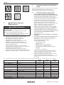
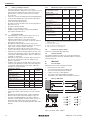
HOERMANN H3G Single-leaf and double-leaf steel doors Instrukcja obsługi
- Typ
- Instrukcja obsługi

480939 M2.4 RE / 04.2022
DE Anleitung für Planung, Montage, Betrieb und Wartung
Ein- und zweiflüglige Stahltüren (OD-Türen, H3G, H3VM, H16G, HS75, H16S1)
EN Instructions for planning, fitting, operating and maintenance
Single-leaf and double-leaf steel doors (OD-doors, H3G, H3VM, H16G, HS75, H16S1)
FR
Instructions pour la conception, le montage, le fonctionnement et la
maintenance
Portes en acier à 1 et 2 vantaux (OD-portes, H3G, H3VM, H16G, HS75, H16S1)
NL Handleiding voor planning, montage, bediening en onderhoud
Eén- en tweevleugelige stalen deuren (OD-deuren, H3G, H3VM, H16G, HS75, H16S1)
IT
Istruzioni per la pianificazione, il montaggio, il funzionamento e la
manutenzione
Porte d’acciaio ad uno e a due battenti (Porte OD, H3G, H3VM, H16G, HS75, H16S1)
+PL HU CS SL RO
M2.4
M1.1 ➞ M1.3

DEUTSCH .................................3
ENGLISH ..................................9
FRANÇAIS ................................15
NEDERLANDS.............................21
ITALIANO.................................27
POLSKI ..................................33
MAGYAR .................................39
ČESKY ...................................45
SLOVENSKO ..............................51
ROMÂNĂ .................................57

Inhaltsverzeichnis
Sehr geehrte Kundin, sehr geehrter Kunde,
wir freuen uns darüber, dass Sie sich für ein Qulitätsprodukt
aus unserem Hause entschieden haben.
1 Zu dieser Anleitung
Bitte lesen und beachten Sie diese Anleitung. Sie gibt Ihnen
wichtige Informationen zu Einbau, Wartung und Pflege Ihrer
Stahltür und ist ein wichtiges Dokument für die Bauakte.
Sprechen Sie mit unserem Kundendienst, wenn Sie nach dem
Durcharbeiten dieser Anleitung noch Fragen haben.
Beachten Sie die folgenden Anleitungen für Planung,
Montage, Betrieb und Wartung entsprechend Ihrer
Zargenform.
• M1.1 Modul Eckzarge
• M1.2 Modul Dryfix, U- Zargen und Blockzargen
• M1.3 Modul Eck- und Ergänzungszargen, Dryfix und
Ergänzungszargen
1.1 Verwendete Warnhinweise
Das allgemeine Warnsymbol kennzeichnet eine Gefahr, die zu
Verletzungen oder zum Tod führen kann. Im Textteil wird das allge-
meine Warnsymbol in Verbindung mit den nachfolgend beschriebenen
Warnstufen verwendet. Im Bildteil verweist eine zusätzlich Angabe auf
die Erläuterungen im Textteil.
GEFAHR
Kennzeichnet eine Gefahr, die unmittelbar zum Tod oder zu schweren
Verletzungen führt.
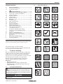
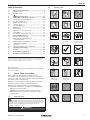
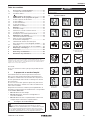
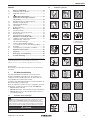
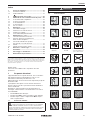
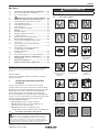
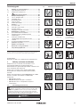
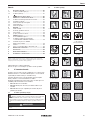
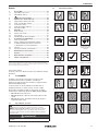
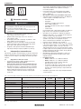
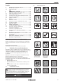
1.2 Verwendete Symbole
Feuerschutz Rauchschutz Sicherheitstür
Schallschutz Funktionstür Wichtiger Hinweis
Siehe Textteil Siehe Bildteil Siehe Einbauanleitung
im Zubehörpaket
Als Zubehör zu
bestellen
Korrektes Vorgehen Unzulässiges Vorgehen
(Vorgehensweise)
Schweißen Bohren Elektrischer Türöffner
Einbruchgefahr auf
Öffnungsseite
Einbruchgefahr auf
Schließseite
Fluchtweg
Holz Mauerwerk / Beton Porenbeton
Gips Beton Mörtel
Zargendichtung DämmstoffA
(EN13501-1)
1 Zu dieser Anleitung ................................................. 3
1.1 Verwendete Warnhinweise ........................................ 3
1.2 Verwendete Symbole ................................................ 3
2 Sicherheitshinweise ....................................... 4
3 Informationen zu den Türeigenschaften ............... 4
3.1 Feuerschutz- und Rauchschutztüren ........................ 4
3.2 Schallschutztüren ..................................................... 6
3.3 Einbruchschutztüren ................................................. 6
3.4 Funktionstüren .......................................................... 6
3.5 Außenanwendung ..................................................... 6
4 Montage ................................................................... 6
4.1 Vor der Montage ....................................................... 6
4.2 Maße nach EN12519 ............................................... 6
4.3 Bei der Montage ....................................................... 6
4.4 Hinweise zum Bildteil ................................................ 7
5 Wartung und Pflege ................................................ 7
5.1 Jährliche Wartungsarbeiten ...................................... 7
5.2 Inbetriebnahme und Wartung
von Panikverschlüssen ............................................. 7
5.3 Erforderliche Oberflächenbehandlung
fürElemente mit Standardgrundierung ..................... 7
5.4 Reinigung .................................................................. 7
5.5 Pflege von Edelstahlbauteilen ................................... 7
6 Etikettierung und Kennzeichnung ......................... 8
7 Allgemeines ............................................................. 8
8 Demontage und Entsorgung .................................. 8
9 Leistungserklärung ................................................. 8
Weitergabe sowie Vervielfältigung dieses Dokuments, Verwertung und Mitteilung
seines Inhalts sind verboten, soweit nicht ausdrücklich gestattet. Zuwiderhandlungen
verpflichten zu Schadenersatz. Alle Rechte für den Fall der Patent-, Gebrauchsmuster-
oder Geschmacksmustereintragung vorbehalten. Änderungen vorbehalten.
480939 M2.4 RE / 04.2022 3
DEUTSCH

2 Sicherheitshinweise
GEFAHR
Lebensgefahr beim Einbau der Stahltür
Beim Einbau kann die Tür oder der Türrahmen umfallen und
dabei Personen erschlagen.
▶ Sichern Sie Tür und Zarge vor und während der
Montagearbeit gegen Umfallen.
• Setzen Sie nur qualifiziertes und unterwiesenes Personal
für Montage und Wartung ein.
• Lassen Sie Elektroarbeiten nur von ausgebildeten
Fachkräften durchführen.
• Führen Sie keine Veränderungen durch An- und Umbauten
durch, die die Sicherheit beeinträchtigen können.
• Schließen Sie die Gefahr durch Feuer, Gas, Staub,
Dampf, Rauch, Brand und Explosion bei Schweiß, Brenn-
und Schleifarbeiten aus.
• Vermeiden Sie, dass bei Schweißarbeiten aufschäu-
mende Baustoffe durch Wärmeeintrag reagieren und
dadurch ihre Wirkung verlieren.
3 Informationen zu den
Türeigenschaften
Beachten Sie, dass die Tür einzelne Eigenschaften, eine
Kombination aus den Eigenschaften Feuerschutz,
Rauchschutz, Schallschutz und Einbruchschutz erfüllen kann
oder eine Funktionstür sein kann.
3.1 Feuerschutz- und Rauchschutztüren
• Die jeweilige Zulassung können Sie unter
www.hoermann.de/dokumentation/
zulassungsbescheide-fuer-feuerschutzabschluesse/
einsehen. Die Zulassung muss an der Verwendungsstelle
vorliegen.
• Die angegeben Informationen sind Mindestanforderungen
für den Einbau in Deutschland. Bei Einbau in anderen
Ländern gelten die jeweiligen nationalen Zulassungen,
wobei die Materialkennwerte mindestens der
DINzugrunde gelegt werden müssen.
• Beachten Sie die DIN18093 (Einbau von Feuerschutz-
türen) und die DIN18100 (Wandöffnungen für Türen)
bzw.die länderspezifischen Vorschriften.
• Der Hersteller kann in Einzelfällen nach §22 und §23 der
Musterbauordnung eine Übereinstimmungserklärung
ausstellen.
• Der Betreiber ist für den einwandfreien Zustand der
Tür verantwortlich.
• In Deutschland dürfen Federbänder an Türen und
Klappen mit folgenden Eigenschaften nicht verwendet
werden:
– Flügelgewicht > 80kg
– Verglasung
– Einbau in Montagewände
(Ausnahme: Maße< 1000 × 1000mm)
– Kombination als Rauchschutztüren nach DIN18095
– 2 - flügelig
Außerhalb Deutschlands können andere Vorschriften
gelten, allerdings empfehlen wir die Einhaltung der deut-
schen Vorgaben.
• Verwenden Sie Beschläge, Schlösser, Schließmittel und
Elektroanbauteile nur, wenn sie Bestandteil der Türzulas-
sung sind oder eine Freigabe des Herstellers vorliegt.
• Bauen Sie 3 - seitig gefälzte Türen ohne unteren Schacht-
abschluss, in Schächten auf unterstem Bodenniveau ein.
• Gipskartonwände und Wanddicken: siehe Tab.1:
• Zulässige Wände und Wanddicken: siehe Tab.2:
• Hinterfüllen Sie die Zarge mit mineralischem Mörtel auf
Zementbasis, z.B. LM21 von Sakret, wenn es in der
Einbausituation nicht anders beschrieben wird. Bei
T30 / EI230 muss der Zargenspiegel nicht zwingend mit
Mörtel verfüllt werden. Spreizen Sie U-Zargen und
Eckzargen (mit und ohne Gegenzargen) vor dem
Hinterfüllen ab, damit sie sich durch den Druck des
Mörtels nicht verbiegen.
• Verwenden Sie bei Feuerschutz einen Drücker mit
Fallverdeck oder einen Schließzylinder und bei
Rauchschutz einen Schließzylinder.
• Rauchschutz:
– RS 65 - 1: AbPNr. P - 14 - 001829 - PR01-ift
– RS 65 - 2: AbPNr. P - 14 - 001829 - PR02-ift
– Verwenden Sie Bodendichtungen und Dichtungskeile
(siehe Bildteil Punkt3.5 und 4).
– Wenn die Zarge nicht komplett mit Mörtel hinterfüllt
ist, müssen Sie den Zargenanschluss an die
angrenzenden Bauteile versiegeln. Versiegeln Sie
beide Seiten und den Fußbereich lückenlos mit
dauerelastischem Material.
• Setzen Sie Verglasungen von Feuerschutztüren keiner
direkten Sonnenstrahlung aus.
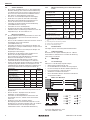
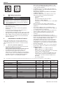
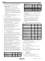
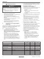
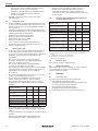
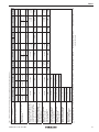
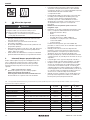
Tab. 1: Zulässige F90A Montagewände mit Mindestwanddicken für Feuerschutz- und Rauchschutztüren, Höhe ≤5000mm
Prüfzeugnis-Nr. Wand H3OD
H_30OD
H3-1G
H_30D1
1) H3-2VM
H_30D2
P-3310/563/07-MPABS Knauf W112 ≥100mm ≥100mm ≥100mm
P-3391/170/08-MPABS Knauf W131 ≥116mm –– ––
P-3310/563/07-MPABS Knauf W132 ≥100mm –– ––
P-3202/2028-MPABS Knauf W352 / W353 ≥100mm ≥100mm ≥100mm
P-3956/1013-MPABS RiGips MW12RF, MW12RFI, MW12HA,
MW12DH, MW12BF, MW12RFWF, MW12GX ≥100mm ≥100mm ≥100mm
P-3014/1393-MPABS RiGips MW11DD ≥100mm ≥100mm ≥100mm
P-3020/0109-MPABS RiGips BW13DDRF ≥165mm –– ––
P-SAC-02/III-681 SW11 – SW14 ≥100mm ≥100mm ≥100mm
P-3391/0890-MPABS SW18 –– –– ––
P-2100/100/17-MPABS Promat 450.81 ≥140mm –– ––
P-11-003478-PR01 B + M W50 / 100 – W100 / 150 ≥100mm –– ––
P-3854/1372-MPABS Fermacell 1S31/3.1 ≥95mm ≥95mm ≥95mm
1) max. 2750 × 2750mm
4480939 M2.4 RE / 04.2022
DEUTSCH

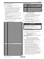
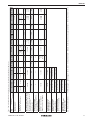
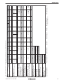
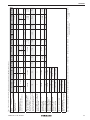
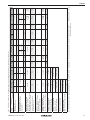
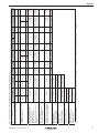
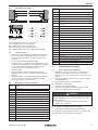
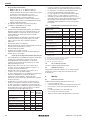
Tab. 2: Zulässige Wände und Mindestwanddicken für Feuerschutz- und Rauchschutztüren (mm) siehe 4.2
Stahltür
Wand
H3-1OD
H_30-1OD
H3-2OD
H_30-2OD
H3-1G
H_30D1
H3-2VM
H_30D2 H6-1OD H6-2OD H16-1G
H_90D1
H16-2G
H_90F-2
H16-S1
H_90E-1
H16-1OD
H_90-1OD
H16-2OD
H_90-2OD
Beton DIN1045-1, Festigkeit≥C12/15 1) k≤ 2500 2) k> 2500 1) k≤ 2500 2) k> 2500 e≤ 1320
100 140 100 140 140 140 140 140 140 120 140 140
Mauerwerk DIN1053-1,
Steinfestigkeit≥12, Mörtelgruppe ≥2 1) k≤ 2500 k> 2500 1) k≤ 2500 2) k> 2500
e≤ 1250
und
k≤ 1750
e≤ 1500
und
k≤ 2500
e≤ 1250
k≤ 2500
e≤ 1500
k≤ 2500
115 175 115 175 175 175 115 175 175 240 175 115 7) 175 175
Porenbeton-Block oder Plan steine,
DIN4165-3, Festigkeitsklasse ≥4,
Porenbetonplatten nach allgemeiner
bauaufsichtlicher Zulassung,
Festigkeitsklasse≥4.4
k≤ 2500 k≤ 2500 6) e≤ 1320 6)
e≤ 2500
e≤ 1320
k≤ 2500
e≤ 2500
k≤ 2500
150 150 175 175 6) 150 6) 200 200 175 6) 200 6) 200
Montagewand F90-A
nach ABP, Bild1.12 beachten,
max.Höhe 5000mm
3) 3) 3) 3)
Montagewand F90-A
DIN4102-4 / Tab.10.2, Bild1.12
beachten, max.Höhe5000mm
e≤ 1320 e≤ 2500
e≤2750
und
k≤2750
e≤ 1250 e≤ 2500 e≤ 1320
k≤ 2500
e≤ 2500
k≤ 2500
100 100 100 100 100 125 125 100 150
Montagewand F30-A
Bild2D / 2.3 beachten,
max.Höhe5000mm
e≤ 1250 e≤ 2500
100 100
Montagewand F90-B
DIN4102-4 / Tab.10.3,
max.Höhe5000mm
e≤ 1250 und k≤ 2500 e≤ 2500 und k≤ 2500
4) 125 / 5) 130 4) 125 / 5) 130
Montagewand F30-B
AbPNr.: P – SAC-02 / III-668
e≤ 1125 und k≤ 2125
185
Gips-Wandbauplatten
VGOrth, P – SAC02 / III-468,
Bild9/A17 beachten
e≤ 1250 und k≤ 2500
100
Mindestwanddicken 1) ohne Oberteil 2) mit Oberteil 3) siehe Tab. 1: 4) zweischalige Zarge 5) Dryfix 6) Rauchschutz: keine Zulassung in Deutschland 7) Rauchschutz, e≤ 1320
480939 M2.4 RE / 04.2022 5
DEUTSCH

3.2 Schallschutztüren
• Die gesamte Schalldämmung ist von den umgebenden
Bauteilen abhängig. Die resultierende Schalldämmung
von Wand und Tür müssen Sie gesondert nachweisen,
da sie nicht aus dem bewerteten Schalldämmmaß Rw
bzw. R der Tür allein abgeleitet werden kann.
• Achten Sie auf vollständig anliegende Dichtung(en).
• Der Boden muss glatt sein, damit die vollständige
Dichtfunktion der Bodendichtung gewährleistet ist.
• Trennen Sie den Estrich im Schwellenbereich.
• Verwenden Sie Dichtungskeile und Bodendichtung
(sieheBildteil Punkt3.5 und 4).
• Verwenden Sie einen Schließzylinder.
• Hinterfüllen Sie die Zarge vollständig mit Mörtel.
• Verkleben Sie die auf Gehrung geschnittenen Ecken der
Zargendichtung z.B. mit Köratan UC41.
3.3 Einbruchschutztüren
• Die Tür erfüllt ihre Einbrucheigenschaften nur, wenn der
Riegel komplett vorgeschlossen und der Schlüssel
abgezogen ist.
• Sichern Sie die Türblätter an allen RC3 und RC4 Türen an
den Bändern mit je zwei Schrauben
(sieheBildteilPunkt3.3)
• Verwenden Sie bei RC3 nur Eckzargen, Eckzargen mit
Gegenzargen, U-Zargen und Blockzargen, ausgenommen
Einbausituation H1.
• Verwenden Sie bei RC4 nur Eckzargen, Eckzargen mit
Gegenzargen und U-Zargen.
• Hinterfüttern Sie die Zarge bei RC2 mindestens im
Bereich der Verriegelungspunkte, Bänder,
Sicherungsbolzen und Falzluftbegrenzer dauerhaft
druckfest. Druckfestigkeit ca.10N/mm².
• Hinterfüllen Sie die Zarge bei RC3 und RC4 Türen
umlaufend druckfest. Druckfestigkeit ca.10N/mm².
• Stützen Sie die Zarge bei RC2 mindestens im Bereich der
Verriegelungspunkte, Bänder, Sicherungsbolzen und
Falzluftbegrenzer dauerhaft und bei RC3 umlaufend mit
druckfestem Material der nachfolgenden Tabelle ab.
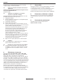
Material zur
Zargenabstützung RC2 RC3 Brand-
schutz
Beton ja ja ja
Mörtel (M10 nach
DINV20000-412) ja ja ja
Nadel- oder Laubholz
(Coder D nach EN338) ja ja nein
Promaboard, Firma Promat ja nein ja
PromatectH, Firma Promat ja ja ja
ROKU V2, Firma Rolf Kuhn ja ja ja
Stahlblech ja nein ja
• Montieren Sie an Türen mit Gläsern den Glashalterahmen
mit Sicherungslaschen oder Sicherungswinkeln auf der
Angriffsseite.
• Messen Sie bei 2 - flügeligen Türen die unteren
Spaltmaße von der Bodenbuchse.
• Verwenden Sie bei Antipaniktüren mit Drücker oder
Stangengriff unseren L- Winkel mit Höckerschwelle,
siehe3.15.
• Stellen Sie sicher, dass sichtbare Zargen-
Befestigungspunkte und Hinterfütterungsteile von der
Angriffsseite aus nicht demontierbar sind (z.B. sichtbare
Schraubenantriebe nach der Zargen-Montage
unbrauchbar machen oder dauerhaft überdecken).
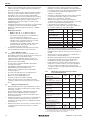
3.3.1 Mindestanforderungen an einbruchhemmende
Türen
Widerstandsklasse
nach DINEN1627 RC2 RC3 RC4
Mauerwerk DIN1053, Teil1 [mm]
Steinfestigkeit ≥12 115 115 240
Stahlbeton, mind. C12 / 15 [mm] 100 120 140
Porenbetonsteine Klasse4 [mm] 175, 115 1) 240 –
Porenbetonplatten Klasse4[mm] 150 – –
Montagewand Knauf W118.de,
WK2 [mm] 101 – –
Holzständerwand nach
DINEN1627 ✓– –
Schließzylinder nach
DIN18252:2006-12 2) 3) 21-, 31-, 71-BZ 42-, 82-BZ
Schutzbeschlag nach
DIN18257:2022-02 2) ES1 (ZA) ES2 (ZA) ES3 (ZA)
Gläser EN356 (Feuerschutz) P5A 4)
P7B 5) P5A 4) –
1) nur 1-Flügler, wir empfehlen Wanddicken ab 150mm
2) Schutzbeschlag oder Schließzylinder muss mit Ziehschutz (ZA) ausgeführt
sein.
3) nicht zwingend im Lieferumfang enthalten
4) nicht in Flucht- und Rettungswegen
5) in Flucht- und Rettungswegen
3.4 Funktionstüren
Die Zargen müssen nicht zwingend hinterfüllt werden.
3.5 Außenanwendung
Beachten Sie die separate Anleitung Art.-Nr.: 5 04 855
beimEinbau im Außenbereich. Sie finden die Anleitung
unter www.hoermann.de.
4 Montage
4.1 Vor der Montage
Klären Sie vor der Montage folgende Fragen:
• Welche Eigenschaften hat die Tür?
• Ist die Wandbauart zum Einbau der Tür geeignet?
• Ist die Höhenlage des Bodens bekannt (Meterriss?)
• In welche Richtung soll die Tür öffnen?
• Sind Bauvorschriften zu beachten?
• Muss die Wand im Bereich der Mauerschutzkästen
ausgestemmt werden?
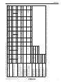
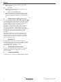
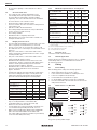
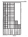
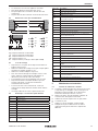
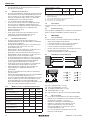
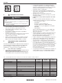
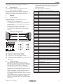
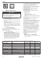
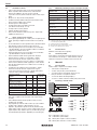
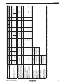
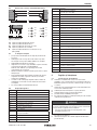
4.2 Maße nach EN12519
Abb. 1:
a
c
d
e
f
gij k l
- 42
- 19
+ 31
- 82
- 36
+ 64
+ 20
0
+ 15
0
Maße
a / g lichte Öffnungsbreite / -höhe
c / i lichte Falzbreite / -höhe
6480939 M2.4 RE / 04.2022
DEUTSCH

d / j Zargenaußenmaßbreite / -höhe
e / k Baurichtmaßbreite / -höhe
f / l lichte Rohbaumaßbreite / -höhe (DIN18100)
4.3 Bei der Montage
• Beachten Sie die Einbauhinweise in den Zubehörpaketen.
• Verwenden Sie Montageteile, wenn sie mitgeliefert
werden, z.B. Dübellaschen, Dübel oder Schrauben.
• Verwenden Sie im Punkt2 die angegebenen Dübel.
• Verwenden Sie in Verbindung mit Eckzarge und
Hochlochziegel bzw. Gipssteinen den Dübel
FUR10 × 80 / 100mm und beachten Sie Punkt2 der
Einbauanleitung.
• Bohren Sie Hochlochziegel und Hohlkammersteine ohne
Schlag.
• Beachten Sie den Mindestrandabstand von 50mm bei
horizontalen bzw. vertikalen Bohrungen und die
Spreizrichtung der Dübel.
• Beachten Sie, dass bei Zargen ohne Bodeneinstand der
untere Montagewinkel vor der Montage entfernt werden
muss.
• Türblattkürzungen sind nicht möglich.
4.4 Hinweise zum Bildteil
siehe Punkt Beschreibung
1a Dünnfalz
1b Dickfalz
1.2a / 1.2b Anzahl der Befestigungspunkte
1.2c Einbauablauf
1.3a Ausbau der Standardtür
1.3b Ausbau der Sicherheitstür
1.4 Zusammenbau der Eckzarge
1.5 Bodenmulde und Montagewinkel
1.6 Befestigungsteile
1.7 Minimaler Randabstand und Spreizrichtung Dübel
1.8 Einbau Schattennutprofile
1.9 Leerrohre in der Zarge
1.10 Einsetzbare E – Öffner
1.11 Mauerschutzkästen in GKF – Wände
1.12 Aufbau GKF-Wände
2.0 Einbausituationen und Zargenformen
3.1a Einbau mit Standardbändern
3.1b Einbau mit 3D-Bändern
3.2 Einstellen der Luftspalte
3.3 Einbau der Sicherheitstür
3.4 Entfernen der Bodenwinkel bei Zargen
ohneBodeneinstand
3.5 Dichtungskeile mit Silikon befestigen
3.6 Einbau der Zargendichtung
3.7 Anheben der Tür
3.8 Spannen des Federbandes Umbau Glasrahmen
3.9 Überprüfung Falleneingriff
3.10 Umbau des Lüftungsgitters
3.11 Umbau Glasrahmen
3.12 Dämmschichtbildner bei Feuer- und Rauchschutz
3.13 Dämmschichtbildner an Sicherungsbolzen
3.14 Kennzeichnung großer Glasflächen
3.15 Paniktüren und RC
siehe Punkt Beschreibung
3.16 Einbau Blockschloss bei Mehrfachverriegelung
3.17 Einbau Ankerplatte für Türhaftmagnet
4Bodendichtungen
5Türschließer
6Bohrungen für Montage Sensoren Drehflügelantriebe
7a Schlüssel bei Paniktüren abziehen
7b Fehlbedienung des Schlosses vermeiden
5 Wartung und Pflege
5.1 Jährliche Wartungsarbeiten
▶ Kontrollieren Sie Türblatt Zarge und alle Anbauteile wie
z.B. Drücker, Schloss, Türschließer und Bänder auf
Funktion und korrosive Schäden.
▶ Fetten Sie Falle, Bandbolzen und Lagerringe mit
Mehrzweckfett.
▶ Schmieren Sie Bolzenschlösser mit Teflonspray.
▶ Kontrollieren Sie die Spaltmaße.
▶ Achten Sie auf die Sichtbarkeit der Kennzeichnung.
▶ Tauschen Sie defekte Teile aus und verwenden Sie nur
Original Ersatzteile des Herstellers.
GEFAHR
Lebensgefahr durch abgelöste Dämmschichtbildner
Durch abgelöste Dämmschichtbildner verliert der
Feuerschutzabschluss seine Funktion.
▶ Ersetzen Sie abgelöste Dämmschichtbildner,
sieheBildteil Punkt3.12.
▶ Tauschen Sie defekte Teile aus.
▶ Verwenden Sie nur Orginal-Ersatzteile des Herstellers.
Wenn Sie Mängel feststellen, die Sie nicht selbst beheben
können, beauftragen Sie eine Fachfirma.
5.2 Inbetriebnahme und Wartung von
Panikverschlüssen
www.hoermann.de/dokumentation/zulassungsbescheide-
fuer-feuerschutzabschluesse/
(siehe Punkt10)
5.3 Erforderliche Oberflächenbehandlung
fürElemente mit Standardgrundierung
Die Oberfläche von Türblatt und Zarge besteht aus einer
Pulvergrundbeschichtung auf Epoxidharz Polyester Basis.
1. Entfernen Sie die Dichtung(en).
2. Schleifen Sie, bis auf die Dämmschichtbildner alle zu
lackierenden Oberflächen an.
3. Reinigen Sie die Oberflächen gründlich.
4. Kleben Sie das Kennzeichnungsschild ab.
5. Verwenden Sie für die Grund- und Endbeschichtung
Lacke, die geeignet und vom Lackhersteller für
pulverlackierte Untergründe freigegeben sind.
Beachten Sie das BFS Merkblatt Nr.24 sowie die
Verarbeitungshinweise der Lackhersteller und fertigen Sie
eine Haftprobe an. Nehmen Sie die Endbehandlung
innerhalb von drei Monaten nach Montage vor, um
Korrosionsschäden zu vermeiden.
Witterungseinflüsse wie z.B. Sonneneinstrahlung können
zu vorübergehender Verformung des Türblattes führen.
Dunkle Anstriche verstärken diesen Effekt, der keinen
Grund zur Beanstandung darstellt. Wir empfehlen helle
und / oder reflektierende Anstriche.
480939 M2.4 RE / 04.2022 7
DEUTSCH

6. Bringen Sie die Dichtung(en) nach dem Trocknen der
Farbe wieder an.
5.4 Reinigung
▶ Reinigen Sie die Oberflächen mit klarem Wasser oder
handelsüblichem Lackreiniger.
5.5 Pflege von Edelstahlbauteilen
▶ Reinigen und pflegen Sie regelmäßig Bauteile aus Edel-
stahl mit der bei Hörmann erhältlichen Edel Glanz Edel-
stahlpflege und tragen Sie diese mit einem weichen Tuch
auf.
6 Etikettierung und Kennzeichnung
Das Etikett der Türtypen D65-1, D65-2, D65-1OD, D65-2OD
ist auf Grundlage der Verordnung (EU) Nr. 305 / 2011 mit dem
CE-Konformitätskennzeichen versehen. Die herangezogene
und angewandte harmonisierte europäische Produktnorm ist
EN14351-1:2006 + A1:2010 „Fenster und Türen –
Produktnorm, Leistungseigenschaften – Teil 1: Fenster und
Außentüren ohne Eigenschaften bezüglich Feuerschutz
und / oder Rauchdichtheit.“ Die Nummer der zugehörigen
CE-Kennzeichnung bzw. Leistungserklärung ist im Falzbereich
der Tür auf dem oben genannten Etikett zwischen dem
Herstellerlogo und dem CE-Konformitätskennzeichen
angegeben.
Türen, auf deren Etikett kein CE-Konformitätskennzeichen
abgebildet ist, fallen nicht in den Anwendungsbereich der
oben genannten harmonisierten europäischen Produktnorm
und dürfen daher nicht über eine CE-Kennzeichnung bzw.
Leistungserklärung verfügen.
7 Allgemeines
Die Inbetriebnahme der Tür ist so lange untersagt, bis
festgestellt wurde, dass sie nach unseren Vorgaben montiert
und auf ihre ordnungsgemäße Funktion überprüft wurde. Bei
einer Veränderung des Produkts verliert die
Leistungserklärung ihre Gültigkeit.
8 Demontage und Entsorgung
Die Demontage erfolgt analog der Montage in umgekehrter
Reihenfolge. Entsorgen Sie das Bauelement nach den
örtlichen Vorgaben.
9 Leistungserklärung
Leistungserklärung siehe Bild1.3: www.hoermann.com/dop
8480939 M2.4 RE / 04.2022
DEUTSCH

Table of Contents
Dear Customer,
We are delighted that you have decided to choose a product
from our company.
1 About These Instructions
Please read and follow these instructions carefully.
Theyprovide you with important information on the fitting,
maintenance and care of your steel door and are an important
document for the construction file.
Should you have any questions after working through these
instructions, please contact our After-Sales Service.
Observe the following instructions for planning, fitting,
operating and maintenance according to your frame type.
• M1.1 Corner frame module
• M1.2 Dryfix, profile frame and block frame module
• M1.3 Corner and counter frame, DryFix and counter
frame module
1.1 Warnings used
The general warning symbol indicates a danger that can lead
to injury or death. In the text section, the general warning symbol will
be used in connection with the caution levels described below. In the
illustrated section, an additional instruction refers back to the
explanation in the text.
DANGER
Indicates a danger that leads directly to death or serious injuries.
1.2 Symbols used
Fire protection Smoke protection Security door
Acoustic rating Function door Important note
See text section See illustrated
section
See installation
instructions in
accessory pack
To be ordered as
an accessory
Correct
procedure
Non-permissible
procedure
Welding Drilling Electric door strike
Possible burglar
attack from
opening side
Possible burglar
attack from
closing side
Escape route
Timber Concrete / brickwork Gas concrete
Plaster Concrete Mortar
1 About These Instructions ....................................... 9
1.1 Warnings used .......................................................... 9
1.2 Symbols used ........................................................... 9
2 Safety Instructions ....................................... 10
3 Information on the Door Features ....................... 10
3.1 Fire doors and smoke-tight doors .......................... 10
3.2 Acoustic-rated doors .............................................. 12
3.3 Burglar protection doors ......................................... 12
3.4 Function doors ........................................................ 12
3.5 Outside application ................................................. 12
4 Fitting ..................................................................... 12
4.1 Before fitting ........................................................... 12
4.2 Dimensions acc. to EN12519 ................................ 12
4.3 When fitting ............................................................. 13
4.4 Information on illustrated section ........................... 13
5 Care and Maintenance ......................................... 13
5.1 Annual maintenance work ...................................... 13
5.2 Initial start-up and maintenance
of anti-panic locks ................................................. 13
5.3 Required surface treatment forelements
withstandard priming ............................................. 13
5.4 Cleaning .................................................................. 14
5.5 Cleaning stainless steel components ..................... 14
6 Labelling and marking .......................................... 14
7 General ................................................................... 14
8 Dismantling and disposal ..................................... 14
9 Declaration of performance ................................. 14
Dissemination as well as duplication of this document and the use and communication
of its content are prohibited unless explicitly permitted. Noncompliance will result in
damage compensation obligations. All rights reserved in the event of patent, utility
model or design model registration. Subject to changes.
480939 M2.4 RE / 04.2022 9
ENGLISH

Frame seal Insulation materialA
(EN13501-1)
2 Safety Instructions
DANGER
Danger to life while fitting the steel door
During fitting, the door or door frame can fall and kill persons.
▶ Prior to and during fitting, secure the door and frame
against falling over.
• Only qualified and instructed personnel may perform
fitting and maintenance.
• Electrical work may only be carried out by qualified
electricians.
• Do not make any alterations through attachments or
conversions which could impair safety.
• Exclude hazards caused by gas, dust, vapour, smoke, fire
and explosion during welding, burning and grinding work.
• When welding, ensure that intumescent materials do not
react as a result of heat input, as this would render the
materials ineffective!
3 Information on the Door Features
Please observe that the door may have single features, a
combination of fire protection, smoke protection, acoustic
rating and burglar protection features, or may be a function
door.
3.1 Fire doors and smoke-tight doors
• The respective approval can be found in the Internet at
www.hoermann.de/dokumentation/
zulassungsbescheide-fuer-feuerschutzabschluesse/.
The approval must be present at the place of use.
• The information given represents the minimum
requirements for installation in Germany. For installation
in other countries, the corresponding national allowances
are valid. However, these must be based on material
parameters equal to or exceeding DIN standard.
• Observe the standards DIN18093 (Installation of Fire
Doors) and DIN18100 (Wall Openings for Doors) or the
country-specific regulations.
• In individual cases, in accordance with §22 and §23 of
the German building code, the manufacturer can issue a
declaration of conformity.
• The operator / owner is responsible for the flawless
condition of the door.
• In Germany, spring hinges must not be used on doors
and hatches having the following characteristics:
– Leaf weight > 80kg
– Glazing
– Fitting in prefabricated walls (exception:
dimensions< 1000 × 1000mm)
– Combination as smoke-tight doors acc. to DIN18095
– Double leaf
Different regulations may apply outside Germany,
however, we recommend compliance with the German
regulations.
• Use only those fittings, locks, closing devices and
electric attached parts that are part of the door approval
or are approved by the manufacturer.
• Doors rebated on 3 sides, without a bottom seal for the
shaft, should be installed at the lowest floor level.
• Gypsum plasterboard walls and wall thicknesses:
seeTab. 1:
• Permissible walls and wall thicknesses: seeTab. 2:
• Backfill the frame with cement-based mineral mortar (e.g.
LM21 from Sakret) provided it is not described differently
in the corresponding installation situation. With
T30 / EI230 the frame face does not necessarily have to
be filled with mortar. Profile frames and corner frames
(with and without counter frames) must be splayed prior
to backfilling to ensure that they do not buckle under the
pressure of the mortar.
• Use a lever handle with catch cover or a lock cylinder for
fire protection, and a lock cylinder for smoke protection.
• Smoke protection:
– RS 65 - 1: AbPNr. P - 14 - 001829 - PR01-ift
– RS 65 - 2: AbPNr. P - 14 - 001829 - PR02-ift
– Use bottom seals and sealing wedges (see illustrated
section, section3.5 and section4).
– If the frame is not completely backfilled with mortar,
seal the frame connection to the adjacent structural
components to provide an unbroken flexible seal on
both sides.
– Use locking cylinders.
Tab. 1: Permissible F90A prefabricated walls with minimum wall thicknesses for fire-rated and smoke-tight doors, height ≤5000mm
Test certificate no. Wall H3OD
H_30OD
H3-1G
H_30D1
1) H3-2VM
H_30D2
P-3310/563/07-MPABS Knauf W112 ≥100mm ≥100mm ≥100mm
P-3391/170/08-MPABS Knauf W131 ≥116mm –– ––
P-3310/563/07-MPABS Knauf W132 ≥100mm –– ––
P-3202/2028-MPABS Knauf W352 / W353 ≥100mm ≥100mm ≥100mm
P-3956/1013-MPABS RiGips MW12RF, MW12RFI, MW12HA,
MW12DH, MW12BF, MW12RFWF, MW12GX ≥100mm ≥100mm ≥100mm
P-3014/1393-MPABS RiGips MW11DD ≥100mm ≥100mm ≥100mm
P-3020/0109-MPABS RiGips BW13DDRF ≥165mm –– ––
P-SAC-02/III-681 SW11 – SW14 ≥100mm ≥100mm ≥100mm
P-3391/0890-MPABS SW18 –– –– ––
P-2100/100/17-MPABS Promat 450.81 ≥140mm –– ––
P-11-003478-PR01 B + M W50 / 100 – W100 / 150 ≥100mm –– ––
P-3854/1372-MPABS Fermacell 1S31/3.1 ≥95mm ≥95mm ≥95mm
1) Max 2750 × 2750mm
10 480939 M2.4 RE / 04.2022
ENGLISH

Tab. 2: Permissible walls and minimum wall thicknesses for fire-rated and smoke-tight doors (mm) see 4.2
Steel door
Wall
H3-1OD
H_30-1OD
H3-2OD
H_30-2OD
H3-1G
H_30D1
H3-2VM
H_30D2 H6-1OD H6-2OD H16-1G
H_90D1
H16-2G
H_90F-2
H16-S1
H_90E-1
H16-1OD
H_90-1OD
H16-2OD
H_90-2OD
Concrete DIN1045-1,
strength≥C12/15
1) k≤ 2500 2) k> 2500 1) k≤ 2500 2) k> 2500 e≤ 1320
100 140 100 140 140 140 140 140 140 120 140 140
Brickwork DIN1053-1,
strength ≥12, mortargroup≥ 2 1) k≤ 2500 k> 2500 1) k≤ 2500 2) k> 2500
e≤ 1250
and
k≤ 1750
e≤ 1500
and
k≤ 2500
e≤ 1250
k≤ 2500
e≤ 1500
k≤ 2500
115 175 115 175 175 175 115 175 175 240 175 115 7) 175 175
Gas concrete stone slabs or concrete
precision blocks DIN4165-3, strength
class≥ 4, Gasconcrete slabs acc. to
general official approval
strengthclass≥ 4.4
k≤ 2500 k≤ 2500 6) e≤ 1320 6)
e≤ 2500
e≤ 1320
k≤ 2500
e≤ 2500
k≤ 2500
150 150 175 175 6) 150 6) 200 200 175 6) 200 6) 200
Prefabricated wall F90-A
acc. toABP, ObserveFigure1.12,
max.height5000mm
3) 3) 3) 3)
Prefabricated wall F90-A
DIN4102-4 / Tab.10.2, Observe
Figure1.12, max.height5000mm
e≤ 1320 e≤ 2500
e≤ 2750
and
k≤ 2750
e≤ 1250 e≤ 2500 e≤ 1320
k≤ 2500
e≤ 2500
k≤ 2500
100 100 100 100 100 125 125 100 150
Prefabricated wall F30-A
Figure2D / 2.3 Observe,
max.height5000mm
e≤ 1250 e≤ 2500
100 100
Prefabricated wall F90-B
DIN4102-4 / Tab.10.3
max.height 5000mm
e≤ 1250 and k≤ 2500 e≤ 2500 and k≤ 2500
4) 125 / 5) 130 4) 125 / 5) 130
Prefabricated wall F30-B
AbPNr.: P – SAC-02 / III-668
e≤ 1125 and k≤ 2125
185
Plaster wallboards
VGOrth, P–SAC02 / III-468
ObserveFigure9/A17
e≤ 1250 and k≤ 2500
100
Minimum wall thicknesses 1) Without top part 2) With top part 3) see.Tab. 1: 3) Double-shell frame 5) Dryfix 6) Smoke protection: no approval in Germany 7) Smoke protection e≤ 1320
480939 M2.4 RE / 04.2022 11
ENGLISH

• Do not expose glazings on fire-rated doors to direct
sunlight.
3.2 Acoustic-rated doors
• The overall acoustic rating is dependent on the
surrounding structural components. The resulting
acoustic rating of wall and door must be verified
separately, as it cannot be derived from the evaluated
acoustic value Rw or R of the door alone.
• Ensure that any seal(s) make full contact.
• The floor must be smooth to ensure the sealing function
of the bottom seal.
• Split the screed in the threshold area.
• Use sealing wedges and a bottom seal (see illustrated
section, section3.5 and section4).
• Use locking cylinders.
• Backfill the frame completely with mortar.
• Glue the mitre-cut corners of the frame seal with, for
example, Köratan UC°41.
3.3 Burglar protection doors
• The door fulfils its burglar-proof characteristics only if the
bolt is completely closed and the key is removed.
• Use two screws each to secure the door leaves of all
RC3 and RC4 doors on the hinges (see illustrated section
point 3.3)
• Only use corner frames, corner frames with counter
frames, profile frames and block frames for RC3, except
for fitting situation H1.
• Only use corner frames, corner frames with counter
frames and profile frames for RC4.
• Backfill the frame with RC2 at least in the area of the
locking points, hinges, security bolts and rebate space
limiters to make it permanently pressure-resistant.
Pressure resistance approx.10N/mm².
• Backfill the frame of RC3 and RC4 doors all-round with
pressure-resistant material. Pressure resistance
approx.10N/mm².
• Permanently support the frame with RC2 at least in the
area of the locking points, hinges, security bolts and
rebate space limiters and with RC3 all-around with
pressure-resistant material per the following table.
Material for frame support RC2 RC3 Fire pro-
tection
Concrete Yes Ye s Yes
Mortar (M10 acc. to
DINV20000-412) Yes Yes Yes
Softwood or hardwood
(CorDaccording to EN338) Yes Yes No
Promaboard by Promat Yes No Yes
PromatectH by Promat Yes Yes Yes
ROKU V2 by Rolf Kuhn Yes Yes Yes
Sheet steel Yes No Yes
• Fit the glazing frame to doors with glass using securing
lugs or securing brackets on the attack side.
• For double-leaf doors, measure the lower gap
dimensions from the bottom bush.
• For anti-panic doors with lever handle or push bar, use
our L-bracket with protruding threshold, see 3.15.
• Make sure that visible frame fixing points and backfill
parts cannot be dismantled from the attack side
(e.g.make visible screw drives unusable or permanently
cover them after fitting the frame).
3.3.1 Minimum requirements for security doors
Resistance class
acc.toDINENV1627 RC2 RC3 RC4
Brickwork DIN1053 part1 [mm]
strength ≥12 115 115 240
Reinforced concrete, at least
C12 / 15[mm] 100 120 140
Gas concrete blocks
class4[mm] 175, 115 1) 240 –
Gas concrete slabs class4 [mm] 150 – –
Prefabricated wall Knauf W118.
de, WK2 [mm] 101 – –
Timber partition wall acc. to
DINEN1627 ✓– –
Profile cylinder acc. to
DIN18252:2006-12 2) 3) 21-, 31-, 71-BZ 42-, 82-BZ
Protective fittings acc. to
DIN18257:2022-02 2) ES1 (ZA) ES2 (ZA) ES3 (ZA)
EN356 glazing (fire protection) P5A 4) /
P7B 5) P5A 4) –
1) Only single-leaf doors, we recommend wall thicknesses of 150mm or more
2) Protective fitting or profile cylinder must be equipped with pull-off
protection (ZA).
3) Not necessarily included in scope of delivery
4) not in escape and rescue routes
5) in escape and rescue routes
3.4 Function doors
The frames need not be backfilled.
3.5 Outside application
Please observe the separate instructions art. no.: 504 855
when fitting outdoors. You will find these instructions
at www.hoermann.de.
4 Fitting
4.1 Before fitting
Before fitting, please clarify the following questions:
• What characteristics does the door have?
• Is the wall structure suitable for installing the door?
• Is the floor height known (metre line)?
• In which direction should the door open?
• Do any building regulations need to be considered?
• Does the wall need to be chiseled out in the area of the
wall protective boxes?
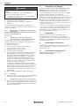
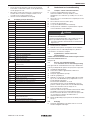
4.2 Dimensions acc. to EN12519
Fig. 2:
a
c
d
e
f
gij k l
- 42
- 19
+ 31
- 82
- 36
+ 64
+ 20
0
+ 15
0
Dimensions
a / g Clear opening width / height
12 480939 M2.4 RE / 04.2022
ENGLISH

c / i Clear rebate width / height
d / j Overall frame dimension width / height
e / k Ordering width / height
f / l Clear unfinished structure dimension
width / heightacc.to (DIN18100)
4.3 When fitting
• Observe the fitting instructions in the accessory packs.
• Use fitting material if it is supplied, e.g. dowel brackets,
plugs or screws.
• Use the plugs indicated in section 2.
• In combination with corner frame and vertically
perforated brick or plaster, use the dowel
FUR10×80 / 100mm and follow item 2 in the fitting
instructions.
• Drill the vertically perforated brick and hollow bricks
without impact.
• Note a minimum edge distance of 50mm for horizontal/
vertical holes as well as the expansion direction of the
dowel.
• Please note that, for frames for finished floors, the
bottom fitting bracket must be removed before fitting.
• Door leaves cannot be shortened.
4.4 Information on illustrated section
See section Description
1a Thin rebate
1b Thick rebate
1.2a / 1.2b Number of fixing points
1.2c Fitting situations
1.3a Removing the standard door
1.3b Removing the security door
1.4 Assembling the corner frame
1.5 Floor trough and fitting bracket
1.6 Fastenings
1.7 Minimum edge spacing and expansion direction of
the dowel
1.8 Fitting the edge recess profiles
1.9 Tubes in the frame
1.10 Suitable electric strikes
1.11 Wall protective cap in gypsum board walls
1.12 Design of GKF walls
2.0 Fitting situations and frame shapes
3.1a Fitting with standard hinges
3.1b Fitting with 3-way adjustable hinges
3.3 Adjusting the air gaps
3.4 Removing the bottom angles for frames without
bottom recesses
3.5 Fastening the sealing wedges with silicone
3.6 Fitting the frame seal
3.7 Raising the door
3.8 Tensioning the spring hinge
3.9 Latch engagement verification
3.10 Alteration of ventilation grille
3.11 Alteration of glazing frame
3.12 Intumescent coating on fire doors and smoke-tight
doors
3.13 Intumescent coatings at security bolts
3.14 Marking of large glass surfaces
3.15 Anti-panic doors and RC
3.16 Block lock fitting for multiple-point locking
3.17 Anchor plate fitting for door holding magnet
See section Description
4Bottom seals
5Door closer
6Holes for fitting hinged door operator sensors
7a Removing the key in anti-panic doors
7b Avoiding incorrect operation of the lock
5 Care and Maintenance
5.1 Annual maintenance work
▶ Check the door leaf, frame and all add-on parts such as
lever handles, locks, door closers and hinges for function
and corrosive damage.
▶ Grease the latch, hinge bolts and bearing rings with
multi-purpose grease.
▶ Lubricate bolt locks with Teflon spray.
▶ Check the gap dimensions.
▶ Make sure that the marking is visible.
▶ Replace defective parts and use only original spare parts
from the manufacturer.
DANGER
Danger to life due to detached intumescent coatings
The fire door loses its function if the intumescent coatings
are detached.
▶ Replace intumescent coatings that have detached,
seeillustrated section3.12.
▶ Replace defective parts.
▶ Only use original spare parts from the manufacturer.
If you discover defects that you yourself cannot remedy, call
in a specialist company.
5.2 Initial start-up and maintenance of anti-panic
locks
www.hoermann.de/dokumentation/zulassungsbescheide-
fuer-feuerschutzabschluesse/
(See section10)
5.3 Required surface treatment forelements
withstandard priming
The surface of door leaf and frame consists of a primer
powder coating on epoxy resin polyester basis.
1. Remove the seal(s).
2. With the exception of the intumescent coatings, sand all
of the surfaces to be painted.
3. Clean the surfaces thoroughly.
4. Tape off the ID plate.
5. For the primer and final coating, use paints that are
suitable and approved by the paint manufacturer for
powder-coated subsurfaces.
We recommend light and / or reflective paints. Please
note BFSinformationsheetno.24, follow thedirections
of the paint manufacturer and test asample surface.
Finish the products within three months of fitting to avoid
corrosion damage.
We recommend light and / or reflective paints. Please
note BFSinformationsheetno.24, follow thedirections
of the paint manufacturer and test asample surface.
Finish the products within three months of fitting to avoid
corrosion damage.
6. After the paint has dried, reattach the seal(s).
480939 M2.4 RE / 04.2022 13
ENGLISH

5.4 Cleaning
▶ Clean the surfaces with clear water or conventional paint
cleaner.
5.5 Cleaning stainless steel components
▶ Regularly clean stainless steel components by applying
“Edel Glanz” stainless steel cleaner (available from
Hörmann) with a soft cloth.
6 Labelling and marking
The label for door types D65-1, D65-2, D65-1OD, D65-2OD
bears the CE conformity mark based on the (EU) Directive no.
305/2011. The European product standard used and applied
is EN14351-1:2006 + A1:2010 “Windows and doors – Pro-
ductstandard, performance characteristics – Part1: Windows
and external pedestrian doorsets without resistance to fire
and/or smoke leakage characteristics.” The number of the
corresponding CE mark or declaration of performance is indi-
cated in the rebate area of the door on the above-mentioned
label between the manufacturer logo and the CE conformity
mark.
The above-mentioned harmonised European product
standard does not apply for doors that do not bear a CE
conformity mark on their labels; thus those doors must not
have a CE mark and a declaration of performance.
7 General
Putting the door into operation is prohibited until it has been
established that the door has been installed in accordance
with our specifications and its function has been properly
tested. A product‘s declaration of performance becomes
invalid if an alteration to the product is carried out.
8 Dismantling and disposal
Dismantling is done in the reverse order of fitting. Dispose of
the construction component in accordance with local
regulations.
9 Declaration of performance
Declaration of performance see section 1.3:
www.hoermann.com/do
14 480939 M2.4 RE / 04.2022
ENGLISH

Table des matières
Cher client,
Nous vous remercions d’avoir opté pour un produit de notre
société.
1 A propos de ce mode d’emploi
Lisez attentivement et suivez les présentes instructions.
Ellesvous fournissent des informations importantes pour
l’installation, la maintenance et l’entretien de votre porte en
acier et représentent un document essentiel pour le dossier
de construction.
Si vous avez encore des questions après avoir parcouru les
présentes instructions, veuillez vous mettre en relation avec
notre service clientèle.
Respectez les instructions suivantes pour la planification, le
montage, le fonctionnement et la maintenance correspondant
à votre forme d’huisserie.
• M1.1 Module huisserie d’angle
• M1.2 Module Dryfix, huisseries enveloppantes et
huisseries tubulaires
• M1.3 Module huisseries complémentaires et huisseries
d’angle, Dryfix et huisseries complémentaires
1.1 Consignes de sécurité utilisées
Ce symbole général d’avertissement désigne un danger
susceptible de causer des blessures graves ou la mort. Dans la partie
texte, le symbole général d’avertissement est utilisé en association
avec les degrés de danger décrits ci-dessous. Dans la partie illustrée,
une indication supplémentaire renvoie aux explications du texte.
DANGER
Désigne un danger provoquant immanquablement la mort ou des
blessures graves.
1.2 Symboles utilisés
Coupe-feu Anti-fumée Porte de sécurité
Insonorisation Porte de fonction Remarque
importante
Voir partie texte Voir partie illustrée Voir instructions de
montage du paquet
d’accessoires
A commander
comme accessoire
Procédure
correcte
Procédure
interdite
Soudure Perçage Gâche électrique
Risque d’intrusion
sur le côté
d’ouverture
Risque d’intrusion
sur le côté de
fermeture
Issue de secours
Bois Maçonnerie / béton Béton cellulaire
Plâtre Béton Mortier
1 A propos de ce mode d’emploi ............................ 15
1.1 Consignes de sécurité utilisées .............................. 15
1.2 Symboles utilisés .................................................... 15
2 Consignes de sécurité ................................. 16
3 Informations sur les propriétés de porte ............ 16
3.1 Portes coupe-feu et anti-fumée .............................. 16
3.2 Portes antibruit ....................................................... 18
3.3 Portes anti-intrusion ............................................... 18
3.4 Portes de fonction .................................................. 18
3.5 Utilisation en extérieur ............................................ 18
4 Montage ................................................................. 18
4.1 Avant le montage .................................................... 18
4.2 Dimensions selon la norme EN12519 .................... 19
4.3 Lors du montage ..................................................... 19
4.4 Remarques concernant la partie illustrée ............... 19
5 Maintenance et entretien ..................................... 19
5.1 Travaux de maintenance annuels ........................... 19
5.2 Mise en service et maintenance
de fermetures antipanique ...................................... 20
5.3 Traitement de surface nécessaire pour
blocs-portes avec couche d’apprêt standard ........ 20
5.4 Nettoyage ............................................................... 20
5.5 Entretien des composants en acier inoxydable ...... 20
6 Etiquetage et marquage ....................................... 20
7 Généralités ............................................................ 20
8 Démontage et élimination .................................... 20
9 Déclaration de performance ................................ 20
Toute transmission ou reproduction de ce document, toute exploitation ou
communication de son contenu sont interdites, sauf autorisation expresse. Tout
manquement à cette règle est illicite et expose son auteur au versement de dommages
et intérêts. Tous droits réservés en cas de dépôt d’un brevet, d’un modèle d’utilité ou
d’agrément. Sous réserve de modifications.
480939 M2.4 RE / 04.2022 15
FRANÇAIS

Joint d’huisserie Matériau isolantA
(EN13501-1)
2 Consignes de sécurité
DANGER
Danger mortel lors du montage de la porte en acier
Durant le montage, la porte ou l’encadrement de porte sont
susceptibles de choir sur une personne.
▶ Avant et pendant les travaux de montage, protégez la
porte et l’huisserie de toute chute.
• Ne confiez le montage et l’entretien qu’à un personnel
qualifié et formé.
• Ne confiez les travaux électriques qu’aux seuls
professionnels formés.
• Ne procédez à aucune extension ou modification
susceptible d’affecter la sécurité de la porte.
• Lors des travaux de soudure, de brasage ou de meulage,
assurez-vous que tout danger d’incendie et d’explosion
ou autres dangers provoqués par des éléments tels que
feu, gaz, poussière, vapeur ou fumée sont exclus.
• Lors de travaux de soudure, évitez que les matériaux de
construction moussants ne réagissent sous l’influence de
la chaleur et ne perdent par là leur effet.
3 Informations sur les propriétés de
porte
Veuillez noter que la porte peut posséder des propriétés
individuelles, une combinaison de propriétés coupe-feu, anti-
fumée, insonorisantes et anti-intrusion ou être une porte de
fonction.
3.1 Portes coupe-feu et anti-fumée
• Vous pouvez consulter l’agréation correspondante sur le
site www.hoermann.de/dokumentation/
zulassungsbescheide-fuer-feuerschutzabschluesse/.
L’agréation doit être présente sur le site d’utilisation.
• Les informations indiquées correspondent aux exigences
minimales pour une installation en Allemagne. En cas
d’installation dans d’autres pays, les agréations
nationales respectives s’appliquent. Toutefois, les valeurs
caractéristiques des matériaux doivent au minimum
correspondre aux normes DIN.
• Observe the standards DIN18093 (Installation of Fire
Doors) and DIN18100 (Wall Openings for Doors) or the
country-specific regulations.
• Dans certains cas, le fabricant peut établir une
déclaration de conformité selon les §22 et 23 du code
modèle de la construction.
• L’exploitant est responsable de l’état correct de la
porte.
• En Allemagne, les paumelles à ressort ne doivent pas
être utilisées sur les portes et les trappes possédant les
caractéristiques suivantes:
– Poids de vantail > 80kg
– Vitrage
– Pose sur parois préfabriquées
(exception:dimensions< 1000 × 1000mm)
– Combinaison comme portes coupe-feu selon la
norme DIN18095
– A 2 vantaux
D’autres prescriptions sont applicables en dehors de
l’Allemagne, toutefois nous vous recommandons de
respecter les directives allemandes.
• Parois en carton-plâtre et épaisseurs de paroi (en mm):
voir Tab. 1:
• Parois et épaisseurs de paroi autorisées: voir Tab. 2:
• Utilisez uniquement les ferrures, serrures, moyens de
fermeture et pièces électriques compris dans l’agréation
de la porte ou disposant d’une autorisation expresse du
fabricant.
• Montez les portes à recouvrement de ferrure sur 3 côtés
sans fermeture de regard inférieure dans des regards au
niveau de sol le plus bas.
• Procédez à un remplissage arrière de l’huisserie à l’aide
de mortier minéral à base de ciment (par exemple LM 21
de Sakret), si cela ne va toutefois pas à l’encontre de la
situation de montage. Pour les modèles T30 / EI230, l’aile
de recouvrement ne doit pas obligatoirement être remplie
de mortier. Avant le remplissage arrière, étançonnez les
huisseries enveloppantes et huisseries d’angle (avec ou
sans contre-huisserie) afin d’éviter qu’elles ne fléchissent
sous la pression du mortier.
Tab. 1: Cloisons sèches F90A homologuées avec épaisseurs mur minimales pour portes coupe-feu et anti-fumée, hauteur ≤ 5000mm
Rapport de test n° Paroi H3OD
H_30OD
H3-1G
H_30D1
1) H3-2VM
H_30D2
P-3310/563/07-MPABS Knauf W112 ≥100mm ≥100mm ≥100mm
P-3391/170/08-MPABS Knauf W131 ≥116mm –– ––
P-3310/563/07-MPABS Knauf W132 ≥100mm –– ––
P-3202/2028-MPABS Knauf W352 / W353 ≥100mm ≥100mm ≥100mm
P-3956/1013-MPABS RiGips MW12RF, MW12RFI, MW12HA,
MW12DH, MW12BF, MW12RFWF, MW12GX ≥100mm ≥100mm ≥100mm
P-3014/1393-MPABS RiGips MW11DD ≥100mm ≥100mm ≥100mm
P-3020/0109-MPABS RiGips BW13DDRF ≥165mm –– ––
P-SAC-02/III-681 SW11 – SW14 ≥100mm ≥100mm ≥100mm
P-3391/0890-MPABS SW18 –– –– ––
P-2100/100/17-MPABS Promat 450.81 ≥140mm –– ––
P-11-003478-PR01 B + M W50 / 100 – W100 / 150 ≥100mm –– ––
P-3854/1372-MPABS Fermacell 1S31/3.1 ≥95mm ≥95mm ≥95mm
1) Max. 2750 × 2750mm
16 480939 M2.4 RE / 04.2022
FRANÇAIS

Tab. 2: Parois homologuées et épaisseurs mur minimales pour portes coupe-feu et anti-fumée (mm) voir 4.2
Porte en acier
Paroi
H3-1OD
H_30-1OD
H3-2OD
H_30-2OD
H3-1G
H_30D1
H3-2VM
H_30D2 H6-1OD H6-2OD H16-1G
H_90D1
H16-2G
H_90F-2
H16-S1
H_90E-1
H16-1OD
H_90-1OD
H16-2OD
H_90-2OD
Béton selon la norme DIN1045-1,
stabilité≥C12/15
1) k≤ 2500 2) k> 2500 1) k≤ 2500 2) k> 2500 e≤ 1320
100 140 100 140 140 140 140 140 140 120 140 140
Maçonnerie selon la norme
DIN1053-1, résistanceà la pierre ≥12,
groupe de mortier ≥2
1) k≤ 2500 k> 2500 1) k≤ 2500 2) k> 2500
e≤ 1250
ou
k≤ 1750
e≤ 1500
ou
k≤ 2500
e≤ 1250
k≤ 2500
e≤ 1500
k≤ 2500
115 175 115 175 175 175 115 175 175 240 175 115 7) 175 175
Bloc en béton cellulaire ou parpaings
DIN4165-3, classe de résistance≥4,
Plaques de béton cellulaire selon
par.=autorisation générale de l’office
de construction, cl.derésistance≥4.4
k≤ 2500 k≤ 2500 6) e≤ 1320 6)
e≤ 2500
e≤ 1320
k≤ 2500
e≤ 2500
k≤ 2500
150 150 175 175 6) 150 6) 200 200 175 6) 200 6) 200
Paroi préfabriquée F90A
selon ABP, Fig.1.12, respectez la
hauteur max.de5000mm
3) 3) 3) 3)
Paroi préfabriquée F90A
DIN4102-4/Tab.10.2, Fig.1.12,
respectez la hauteur max.de5000mm
e≤ 1320 e≤ 2500
e≤ 2750
ou
k≤ 2750
e≤ 1250 e≤ 2500 e≤ 1320
k≤ 2500
e≤ 2500
k≤ 2500
100 100 100 100 100 125 125 100 150
Paroi préfabriquée F30-A
Fig. 2D / 2.3 respectez la hauteur
max.de5000mm
e≤ 1250 e≤ 2500
100 100
Paroi préfabriquée F90B
DIN4102-4/Tab.10.3
max.de5000mm
e≤ 1250 ou k≤ 2500 e≤ 2500 ou k≤ 2500
4) 125 / 5) 130 4) 125 / 5) 130
Paroi préfabriquée F30-B
ABPNr.: P – SAC-02 / III-668
e≤ 1125 ou k≤ 2125
185
Carreaux à parois en plâtre
VGOrth, P–SAC02 / III-468, Fig.9/A17
e≤ 1250 ou k≤ 2500
100
Epaisseurs mur minimales 1) Sans imposte 2) Avec imposte 3) voir Tab. 1: 4) Huisserie à double tôle 5) Dryfix 6) Protection anti-fumée: pas 7) Protection anti-fumée, e≤ 1320
d‘homologation en Allemagne
480939 M2.4 RE / 04.2022 17
FRANÇAIS

• Pour la protection coupe-feu, utilisez un béquillage avec
pêne masqué ou un cylindre de fermeture, et pour la
protection anti-fumée, un cylindre de fermeture.
• Protection anti-fumée:
– RS 65 - 1: AbPNr. P - 14 - 001829 - PR01-ift
– RS 65 - 2: AbPNr. P - 14 - 001829 - PR02-ift
– Utilisez des joints de sol et des cales d’étanchéité
(voir partie illustrée, points3.5 et 4).
– Si l’huisserie n’est pas complètement remplie de
mortier à l’arrière, scellez le raccord entre l’huisserie
et les éléments de construction attenant sur les deux
faces avec un produit à élasticité durable, sans laisser
d’interstices.
– Utilisez des cylindres de fermeture.
• Les vitrages des portes coupe-feu ne doivent pas être
soumis à un rayonnement solaire direct.
3.2 Portes antibruit
• L’intégralité de l’isolation acoustique dépend des
éléments de construction attenants. Vous devez procéder
à une détermination spécifique de l’isolation acoustique
de la paroi et de la porte en résultant puisqu’elle ne peut
être déduite au seul moyen de l’isolation acoustique
Rwou R évaluée de la porte.
• Assurez-vous que le(s) joint(s) est/sont complet(s).
• Le sol doit être lisse afin d’assurer parfaitement la
fonction d’étanchéité du joint de sol.
• Séparez la chape de béton dans la zone de seuil.
• Utilisez des joints de sol et des cales d’étanchéité
(voirpartie illustrée, points3.5 et 4).
• Utilisez des cylindres de fermeture.
• Procédez à un remplissage arrière complet de l’huisserie.
• Collez les angles coupés en onglet du joint d’huisserie
par exemple avec Köratan UC41.
3.3 Portes anti-intrusion
• La porte ne remplit ses propriétés anti-effraction que si le
verrou est entièrement fermé et que la clé est retirée.
• Fixez les panneaux de porte sur toutes les portes CR 3 et
CR 4 au niveau des paumelles avec deux vis pour chaque
panneau (voir partie illustrée point 3.3).
• N’utilisez pour les portes CR 3 que des huisseries
d’angle, des huisseries d’angle avec contre-huisseries,
des huisseries enveloppantes et des huisseries
tubulaires, excepté pour la situation de montage H1.
• N’utilisez pour les portes CR 4 que des huisseries
d’angle, des huisseries d’angle avec contre-huisseries et
des huisseries enveloppantes.
• Stabilisez l’huisserie CR 2 au moins au niveau des points
de verrouillage, des paumelles, des points d’anti-
dégondage et du limiteur de jeu de feuillure. Résistance à
la pression env.10N/mm².
• Remplissez l’huisserie des portes CR 3 et CR 4 sur tout le
pourtour pour assurer une résistance à la pression.
Résistance à la pression env.10N/mm².
• Etayez durablement l’huisserie CR 2 au moins au niveau
des points de verrouillage, des paumelles, des points
d’anti-dégondage et des limiteurs de jeu de feuillure et,
en cas d’huisserie CR 3, de manière périphérique à l’aide
d’un matériau résistant à la pression selon le tableau
suivant.
Matériau pour étayer
l’huisserie RC2 RC3 Sécurité
coupe-feu
Béton Oui Oui Oui
Mortier (M10 selon
DINV20000-412) Oui Oui Oui
Matériau pour étayer
l’huisserie RC2 RC3 Sécurité
coupe-feu
Résineux ou feuillus
(CouDselon EN338) Oui Oui Non
Promaboard, société Promat Oui Non Oui
PromatectH, société Promat Oui Oui Oui
ROKU V2, société Rolf Kuhn Oui Oui Oui
Tôle d’acier Oui Non Oui
• Montez le châssis à parcloses sur les portes avec vitrage
à l’aide d’étriers de fixation ou d’équerres de fixation du
côté d’attaque.
• Pour les portes à 2vantaux, mesurez l’espace inférieur
de la douille de sol.
• Pour les portes antipanique avec béquillage ou barre de
poussée, utilisez nos équerres en L à seuil bombé,
voir3.15.
• Assurez-vous que les points de fixation visibles de
l’huisserie et les parties du calage ne sont pas
démontables du côté d’attaque (p. ex.: rendez les
entraînements de vis visibles inutilisables ou
recouvrez-les à long terme après le montage de
l’huisserie).
3.3.1 Exigences minimales des portes anti-intrusion
Classe de résistance selon
DINENV1627 RC2 RC3 RC4
Maçonnerie DIN 1053 partie
1[mm], résistanceà la pierre
≥12
115 115 240
Béton armé, min. C12 / 15 [mm] 100 120 140
Briques en béton
cellulaireclasse4[mm] 175, 115 1) 240 –
Plaques en béton
cellulaireclasse4[mm] 150 – –
Bouton cloison sèche W118.de,
CR 2 [mm] 101 – –
Cloison sèche en bois selon la
norme DINEN1627 ✓– –
Cylindre profilé selon
DIN18252:2006-12 2) 3) 21-, 31-, 71-BZ 42-, 82-BZ
Ferrure de protection selon
DIN18257:2022-02 2) ES1 (ZA) ES2 (ZA) ES3 (ZA)
Vitrages EN356 (coupe-feu) P5A 4) /
P7B 5) P5A 4) –
1) Uniquement pour les portes à 1vantail, nous recommandons une
épaisseur de paroi supérieure à 150mm
2) La ferrure de protection ou le cylindre profilé doit être équipé(e) d’une
protection contre l’arrachement (ZA).
3) Ne fait pas nécessairement partie du matériel livré
4) Non réalisable pour les issues de secours
5) Dans les issues de secours
3.4 Portes de fonction
Les huisseries ne doivent pas obligatoirement faire l’objet
d’un remplissage arrière.
3.5 Utilisation en extérieur
Veuillez observer les instructions séparées, n° d’art. 504 855,
lors de la pose en extérieur. Vous trouverez les instructions
àl’adresse www.hoermann.de.
4 Montage
4.1 Avant le montage
Avant le montage, veuillez éclaircir les points suivants:
• Quelles sont les propriétés de la porte?
• Le type de paroi est-il adapté au montage de la porte?
18 480939 M2.4 RE / 04.2022
FRANÇAIS

• Le niveau du sol est-il connu (repère à un mètre)?
• Dans quelle direction la porte doit-elle ouvrir?
• Des prescriptions de construction doivent-elles être
respectées?
• La paroi doit-elle être mortaisée au niveau de l’huisserie?
4.2 Dimensions selon la norme EN12519
Abb. 3:
a
c
d
e
f
gij k l
- 42
- 19
+ 31
- 82
- 36
+ 64
+ 20
0
+ 15
0
Dimensions
a / g Largeur / hauteur d’ouverture libre
c / i Largeur / hauteur de feuillure libre
d / j Largeur / hauteur hors-tout cadre
e / k Largeur / hauteur jour
f / l Largeur / hauteur jour de gros-œuvre (DIN18100)
4.3 Lors du montage
• Respectez les consignes de montage fournies dans les
paquets d’accessoires.
• Utilisez le matériel de montage fourni, par exemple pattes
de fixation à cheviller, chevilles ou vis.
• Utilisez les chevilles indiquées au point 2.
• Avec une huisserie d’angle et une brique creuse ou du
gypse, utilisez la cheville FUR10 × 80 / 100mm et
observez le point 2 de la notice de montage.
• Forez la brique creuse et les parpaings sans à-coups.
• Respectez la distance minimale de 50mm pour les
forages horizontaux ou verticaux et la direction
d’écartement de la cheville.
• Pour les huisseries sans encastrement, notez que
l’équerre de montage inférieure doit être retirée avant le
montage.
• Il est impossible de raccourcir le panneau de porte.
4.4 Remarques concernant la partie illustrée
Voir point Description
1a Feuillure mince
1b Feuillure épaisse
1.2a / 1.2b Nombre de points de fixation
1.2c Situations de montage
1.3a Démontage de la porte standard
1.3b Démontage de la porte de sécurité
1.4 Assemblage de l’huisserie d’angle
1.5 Rainure de sol et équerres de montage
1.6 Matériel de fixation
1.7 Distance minimale au bord et direction d’écartement de
la cheville
Voir point Description
1.8 Montage des profils à rainure
1.9 Tubes vides dans l’huisserie
1.10 Suitable electric strikes
1.11 Boîtiers de protection muraux pour murs en plaques de
carton-plâtre coupe-feu
1.12 En applique pour parois de placo-plâtre coupe-feu
2.0 Situations de montage et formes d’huisserie
3.1a Pose avec paumelles standards
3.1b Pose avec paumelles 3D
3.2 Réglage du jeu
3.3 Montage de la porte de sécurité
3.4 Retrait des équerres de transport en cas d’huisseries
sans encastrement au sol
3.5 Fixer les cales d’étanchéité avec du silicone
3.6 Pose du joint d’huisserie
3.7 Relevage de la porte
3.8 Mise sous tension des paumelles à ressort
3.9 Vérification engagement
3.10 Réadapter la grille d’aération
3.11 Réadapter le châssis vitré
3.12 Composants de la couche isolante pour protection
coupe-feu et anti-fumée
3.13 Créateur de couche isolante sur pointsd’anti-dégondage
3.14 Marking of large glass surfaces
3.15 Portes antipanique et RC
3.16 Pose d’une serrure monobloc en cas de verrouillage
multiple
3.17 Pose d’une plaque d’ancrage pour ventouse
électromagnétique de porte
4Joints de sol
5Ferme-porte
6Perçages pour montage des capteurs des motorisations
pour portes battantes
7a Removing the key in anti-panic doors
7b Avoiding incorrect operation of the lock
5 Maintenance et entretien
5.1 Travaux de maintenance annuels
▶ Contrôlez si le panneau de porte, l’huisserie et tous les
composants (p. ex. béquille, serrure, ferme-porte et
paumelles) fonctionnent bien et s’ils présentent
d’éventuels dommages dus à la corrosion.
▶ Graissez les pêne, axes de paumelle et bagues de
roulement avec de la graisse universelle.
▶ Lubrifiez les serrures à pêne avec un spray PTFE.
▶ Contrôlez les jeux.
▶ Veillez à ce que le marquage soit bien visible.
▶ Remplacez les pièces défectueuses et utilisez
uniquement des pièces détachées originales du
fabricant.
480939 M2.4 RE / 04.2022 19
FRANÇAIS

DANGER
Danger mortel dû à des créateurs de couche isolante
défaits
En raison de créateurs de couche isolante défaits, la
fermeture coupe-feu perd de sa fonction.
▶ Remplacez les créateurs de couche isolante défaits,
voirpartieillustrée, point3.12.
▶ Remplacez les pièces défectueuses.
▶ N’utilisez que les pièces détachées originales du
fabricant.
Si vous identifiez certaines défaillances auxquelles vous
n’êtes pas en mesure de remédier, confiez la réparation à une
entreprise spécialisée.
5.2 Mise en service et maintenance de fermetures
antipanique
www.hoermann.de/dokumentation/zulassungsbescheide-
fuer-feuerschutzabschluesse/
(Voir point10)
5.3 Traitement de surface nécessaire pour
blocs-portes avec couche d’apprêt standard
La surface du panneau de porte et de l’huisserie est
constituée d’un revêtement d’apprêt à base de poudre de
résine polyester époxydique.
1. Retirez le(s) joint(s).
2. Poncez toutes les surfaces à laquer jusqu’aux
composants de la couche isolante.
3. Nettoyez minutieusement les surfaces.
4. Décollez la plaque signalétique.
5. Pour les revêtements d’apprêt et de finition, utilisez une
laque appropriée et homologuée par le fabricant de
laques pour supports avec laquage à base de poudre.
Respectez la fiche technique BFSn°24 ainsi que les
consignes d’utilisation du fabricant de peinture et
effectuez un test d’adhérence. Afin d’éviter tout dégât
dûà la corrosion, procédez à la couche de finition dans
les trois mois suivants le montage.
Les influences climatiques telles que le rayonnement
solaire peuvent entraîner une déformation temporaire du
panneau de porte. Les peintures foncées renforcent cet
effet, ce qui n‘est pas un motif de réclamation. Nous
recommandons des revêtements de couleur claire et/ou
réfléchissants.
6. Après séchage de la peinture, replacez le(s) joint(s).
5.4 Nettoyage
▶ Nettoyez les surfaces à l’eau claire ou à l’aide de produits
de nettoyage pour surfaces laquées du commerce.
5.5 Entretien des composants en acier inoxydable
▶ Nettoyez et entretenez régulièrement les composants en
acier inoxydable en appliquant le produit d’entretien pour
acier inoxydable Edel Glanz (disponible chez Hörmann) à
l’aide d’un chiffon doux.
6 Etiquetage et marquage
L’étiquette des types de porte D65-1, D65-2, D65-1OD,
D65-2OD est pourvue du sigle de conformité CE selon le
décret européen n° 305/2011. La norme de produit
européenne apparentée et connexe est EN14351-1:2006 +
A1:2010 «Fenêtres et portes–Norme produit,
caractéristiques de performance – Partie1: Fenêtres et
blocs-portes extérieurs pour piétons sans caractéristiques de
résistance au feu et/ou dégagement de fumée». Le numéro
du sigle CE ou de la déclaration de performance respectif/
respective figure au niveau de la feuillure de la porte, sur
l’étiquette mentionnée ci-dessus, entre le logo du fabricant et
le sigle de conformitéCE.
Les portes munies d’étiquettes sans sigle de conformité CE
ne sont pas concernées par le domaine d’application de la
norme produits européenne harmonisée ci-dessus et ne
peuvent par conséquent disposer d’un marquage CE et/ou
d’une déclaration de performance.
7 Généralités
La mise en service de la porte est interdite jusqu’à
constatation de sa conformité avec nos prescriptions
d’installation et de son fonctionnement irréprochable. Toute
modification du produit annule la validité de la présente la
déclaration de performance.
8 Démontage et élimination
Le démontage se déroule dans l’ordre inverse des étapes de
montage. Eliminez la menuiserie conformément aux
prescriptions locales.
9 Déclaration de performance
Déclaration de performance voir point 1.3:
www.hoermann.com/dop
20 480939 M2.4 RE / 04.2022
FRANÇAIS
Strona się ładuje...
Strona się ładuje...
Strona się ładuje...
Strona się ładuje...
Strona się ładuje...
Strona się ładuje...
Strona się ładuje...
Strona się ładuje...
Strona się ładuje...
Strona się ładuje...
Strona się ładuje...
Strona się ładuje...
Strona się ładuje...
Strona się ładuje...
Strona się ładuje...
Strona się ładuje...
Strona się ładuje...
Strona się ładuje...
Strona się ładuje...
Strona się ładuje...
Strona się ładuje...
Strona się ładuje...
Strona się ładuje...
Strona się ładuje...
Strona się ładuje...
Strona się ładuje...
Strona się ładuje...
Strona się ładuje...
Strona się ładuje...
Strona się ładuje...
Strona się ładuje...
Strona się ładuje...
Strona się ładuje...
Strona się ładuje...
Strona się ładuje...
Strona się ładuje...
Strona się ładuje...
Strona się ładuje...
Strona się ładuje...
Strona się ładuje...
Strona się ładuje...
Strona się ładuje...
-
 1
1
-
 2
2
-
 3
3
-
 4
4
-
 5
5
-
 6
6
-
 7
7
-
 8
8
-
 9
9
-
 10
10
-
 11
11
-
 12
12
-
 13
13
-
 14
14
-
 15
15
-
 16
16
-
 17
17
-
 18
18
-
 19
19
-
 20
20
-
 21
21
-
 22
22
-
 23
23
-
 24
24
-
 25
25
-
 26
26
-
 27
27
-
 28
28
-
 29
29
-
 30
30
-
 31
31
-
 32
32
-
 33
33
-
 34
34
-
 35
35
-
 36
36
-
 37
37
-
 38
38
-
 39
39
-
 40
40
-
 41
41
-
 42
42
-
 43
43
-
 44
44
-
 45
45
-
 46
46
-
 47
47
-
 48
48
-
 49
49
-
 50
50
-
 51
51
-
 52
52
-
 53
53
-
 54
54
-
 55
55
-
 56
56
-
 57
57
-
 58
58
-
 59
59
-
 60
60
-
 61
61
-
 62
62


HOERMANN H3G Single-leaf and double-leaf steel doors Instrukcja obsługi
- Typ
- Instrukcja obsługi
w innych językach
- italiano: HOERMANN H3G Single-leaf and double-leaf steel doors Istruzioni per l'uso
- slovenčina: HOERMANN H3G Single-leaf and double-leaf steel doors Návod na používanie
- français: HOERMANN H3G Single-leaf and double-leaf steel doors Mode d'emploi
- Nederlands: HOERMANN H3G Single-leaf and double-leaf steel doors Handleiding
- română: HOERMANN H3G Single-leaf and double-leaf steel doors Instrucțiuni de utilizare
Powiązane artykuły

Inne dokumenty
-
Levenhuk DTX RC1 Instrukcja obsługi
-
DELTA DORE TYXAL+ DOI PVC Instrukcja instalacji
-
-
Key Gates Turbo 250 instrukcja
-
STIEBEL ELTRON CNS 50-300 Trend (U) Operation Instruction
-
 Held Furniture Instrukcja obsługi
-
Castorama Porte d'entrée acier Plaques carrés blanc trafic 90 x h.215 cm poussant droit Instrukcja obsługi
