
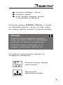
RU
Instrukcja montażu PL
Installation manual UK
Èíñòðóêöèÿ ïî ìîíòàæó
www.elektra.eu
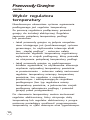
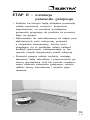
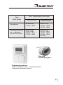
ELEKTRA DM
ELEKTRA UltraTec
• Single-side powered,
power output 10 W/m
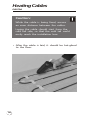
Thin Heating Cables


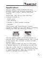
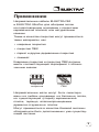
Application
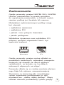
The thin heating cables ELEKTRA DM and
ELEKTRA UltraTec are primarily intended for use
in rooms with a tile or natural stone floor
covering.
Additionally, they can be used with floor
covering materials as:
• Fitted carpet,
• Vinyl flooring,
• Parquet or other wooden covering,
• Laminate.
Fitted carpets and Vinyl flooring, however,
should be suitable for use with electric underfloor
heating and bear the following markings:
The thin heating cables can be laid directly on
concrete floors, self-levelling concrete slab, as well
as old ceramic tiles, terrazzo or water resistant
wooden floors.
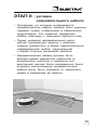
The thin heating cables are laid in a thin layer
of flexible adhesive or self-levelling concrete slab.
They are usually used as a supplementary floor
heating system, in order to provide the user with
a “warm floor effect”. They, can however, be
used as a primary heating system.
o
+C
Fitted carpet
Vinyl flooring
3

4
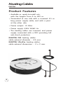
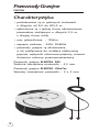
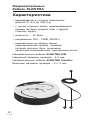
Product Features
• Available as ready-to-install sets,
with the lengths from 9 to 205 m.
• Terminated at one side with a screened 2.5 m
long power supply cable, and with a joint
at the other side.
• Power output: 10 W/m.
• Power supply: 230V 50/60 Hz.
• The heating cables are screened, and power
supply connected with a RCD providing full
anti-shock protection.
ELEKTRA DM heating cables:
cable external diameter – 4.3 mm.
ELEKTRA UltraTec heating cables:
cable external dimensions – 2 x 3 mm.
Heating Cables
ELEKTRA
1
2 3

Because of the thin nature, ELEKTRA UltraTec
cables can be used in applications where
elevating the floor level is not an option.
5
The power output of the heating cables
can vary +/-5% from the provided
nominal specifications.
The heating cables are suitable for
a 230V/50Hz rated voltage.
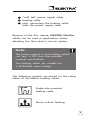
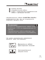
Note:
The following symbols are placed on the rating
labels of the Elektra heating cables:
Single-side powered
heating cable.
Direct in-floor heating.
“cold tail” power supply cable
heating cable
joint connecting the heating cable
with the power supply cable
1
2
3

6
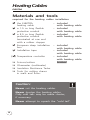
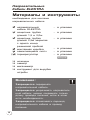
Materials and tools
required for the heating cables installation
the ELEKTRA
heating cable
a 1.5 m long flexible
protective conduit
a 2.5 m long flexible
protective conduit
terminated at one end
with a rubber stopper
European deep installation
box
Installation tape
Temperature controller
Scissors/cutters
Ohmmeter (multimeter)
Insulation Resistance Tester
Tools for cutting chases
in walls and floors
– included
with heating cable
– included
with heating cable
– included
with heating cable
– included
with heating cable
– included
with heating cable
– included
with heating cable
Never cut the heating cables.
Never shorten the heating cables.
Only cold tails may be made shorter,
if necessary.
Never attempt to squash the “cold tail”.
Caution:
( )
option
Heating Cables
ELEKTRA

7
Never attempt a self-repair of the heating
cables. If the heating cables are damaged,
please contact an ELEKTRA authorized
installer.
Never expose the heating cables to
excessive stretching, stress or hit them
with sharp tools.
Never attempt to lay the ELEKTRA DM
heating cable if the ambient temperature
drops below -5°C (for the UltraTec cable:
-20°C ).
Never install the heating cables in places
where fixed furniture is planned (e.g. floor-
level wardrobes, kitchen units, baths).
Never use installation materials other than
those specified in the installation manual.
Never use nails or screws of any kind for
installation of the heating cables.
Caution:
Always install the heating cables
according to the installation manual.
Electrical connection of the heating cables
must be always performed by a certified
electrician.
The minimum distance between the
heating cables and other heat sources
(e.g. hot water pipes) should always
exceed 25 mm.
Caution:

8
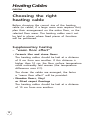
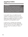
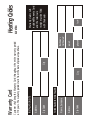
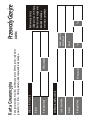
Choosing the right
heating cable
Before choosing the correct size of the heating
cable (or cables, if a large room area requires this),
plan their arrangement on the entire floor, or the
selected floor areas. The heating cables must not
be laid in places where fixed pieces of furniture
will be positioned.
Supplementary heating
– “warm floor effect”
• Ceramic tiles and stone floors
The heating cables should be laid at a distance
of 8 cm from one another. If this distance is
higher than 10 cm, the floor surface temperature
could noticeably feel uneven (the temperature
differences over 2°C).
The closer the cables are arranged, the faster
a “warm floor effect” will be provided.
• Wooden floors, Vinyl
or fitted carpet floorings
The heating cables should be laid at a distance
of 10 cm from one another.
Heating Cables
ELEKTRA

installation box
temperature sensor
9
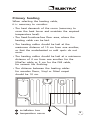
Primary heating
When selecting the heating cable,
it is necessary to consider:
• The heat demands of the room (necessary to
cover the heat losses and maintain the required
temperature level).
• The fixed-furniture-free floor area, where the
heating cable can be laid.
• The heating cables should be laid at the
maximum distance of 10 cm from one another,
so that the underheated or cold spots do not
occur.
• The heating cables should be laid at a minimum
distance of 4 cm from one another for the
UltraTec cable or 5 cm for the DM cable,
for ceramic tile finishing.
• The distance between the heating cables
for wooden floors, Vinyl or fitted carpet
should be 10 cm.
1
2
1
2

10
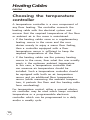
Choosing the temperature
controller
A temperature controller is a core component of
any floor heating. The controller connects the
heating cable with the electrical system and
ensures that the required temperature of the floor
or ambient air in the room is maintained.
• If the heating cables serve as a supplementary
heating source in the room and the user
desires merely to enjoy a warm floor feeling,
then a controller equipped with a floor
temperature sensor is sufficient to keep the
required temperature of the floor.
• If the heating cables are the primary heating
source in the room, then what the user usually
wants is the optimum ambient temperature.
In this case, a temperature controller that
can measure air temperature should be
installed. Such a temperature controller should
be equipped with both an air temperature
sensor and an additional floor temperature
sensor (while measuring the ambient tempera-
ture, it protects the floor and the heating cable
from overheating).
For temperature control, either a manual electro-
nic controller may be used which keeps constant
temperature or a programmable electronic
controller which can be programmed in a daily
and/or a weekly cycle.
Heating Cables
ELEKTRA

11
Heating
type
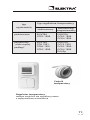
Temperature controller type
Manual
Temperature controller
may be installed under a common faceplate
with a lighting switch (not applicable in the UK).
Temperature
sensor
ELEKTRA
OTD2 1999
ELEKTRA
OCD2 1999
OCD4 1999
Primary
Supplementary
for the “warm
floor effect”
ELEKTRA
OTN 1991
OTN2 1991
OTD2 1999
ELEKTRA
OCC2 1991
OCD2 1999
OCD4 1999
DIGI2p
Programmable

12
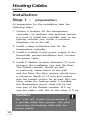
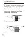
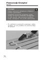
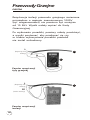
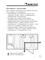
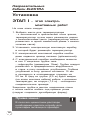
Installation
Step I – preparation
As preparation for the installation take the
following steps:
1. Choose a location for the temperature
controller. For aesthetic and practical reasons,
it is best to install the controller next to the
lighting switches (e.g. under a common
faceplate; not in the UK).
2. Install a deep installation box for the
temperature controller.
3. Install a suitable 3-wire power supply to the
thermostat position/installation box. Connect
the power cable.
4. Install 2 flexible conduits (diameter 15 mm)
between the installation box and the floor.
The flexible conduits should be laid
in previously made chases in the wall
and the floor. The floor groove should have
a minimum depth of 15 mm and extend
into the heated surface for at least 500 mm.
Later, when the heating cable is installed,
the temperature sensor cable will be fed
into one of the flexible conduits (2.5 m),
and the cable’s cold tails to the other (1.5 m).
The “cold tail” should be positioned in
a specially made floor groove - the joint
connecting the heating cable with the
power supply.
Caution:
Heating Cables
ELEKTRA

13
Power supply cable
Deep installation box
for the temperature controller
Flexible protective conduit
for the floor temperature sensor
Flexible protective conduit
for the cable's cold tails
2
2
3
3
4
1
1
2
3 4

14
If the heated area is not adjacent to the
temperature controller and the protective
conduit is extended into the floor for more
than 1.0 m, it may be necessary to install an
additional installation box close to the floor.
Such solution would facilitate the easy
exchange of the temperature sensor.
A draw wire is a flexible wire positioned
inside the protective conduits which helps
feeding the floor sensor cable together with
the cold tails into the deep installation box
easily, just after the plastering or laying
the tiles.
Do not bend the flexible protective
conduits at 90° angle at the junction of
the wall and floor - keep the curve shape.
The curve shape of the protective conduits
guide would enable the easy exchange of
the temperature sensor, if required.
Caution:
Heating Cables
ELEKTRA

15
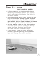
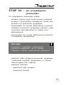
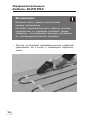
Step II – laying
the heating cable
• A floor prepared for heating cable laying
should be smoothed, cleaned and primed,
which will enable hot-glueing the cable to
the floor surface.
• The temperature sensor cable should be fed
into the protective flexible conduit installed
in the preparation step. Seal the conduits
floor ending with a rubber stopper to protect
the sensor against moisture penetration.
• Lay the heating cable on the floor making
sure that it will not be positioned directly
under the fixed furniture, and fasten
the cable with the installation tape.
If the heating cable has been arranged
wrongly, you can peel off the installation
tape and change the cable's position.
•

16
Caution:
While the cable is being fixed, ensure
an even distance between the cables.
Laying the cable should start from the
cold tail side, so that the cold tail could
easily reach the installation box.
• After the cable is laid, it should be hot-glued
to the floor.
Heating Cables
ELEKTRA

17
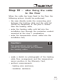
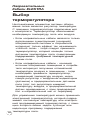
Step III – after fixing the cable
to the floor
When the cable has been fixed to the floor the
following actions should be performed:
• the area directly under the connecting joint
between the heating cable and the cold tail
should be deepened, as the joint is thicker
than the heating cable,
• enter the heating cable cold tail into the
installation box through the protective conduit
mounted at the step 1: preparation,
• enter the temperature sensor cable into the
installation box,
• make a sketch (or photograph) of the heating
cable floor arrangement and the temperature
sensor position in the Warranty Card,
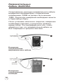
• perform measurements:
- heating wire resistance,
- insulation resistance.
Caution:
The temperature sensor cable
should be positioned just between
the heating cables.

PE
(yellow-green)
L
(brown or
black
N
(blue)
1
1
2
3
Heating wire’s
resistance measurement
Insulation
resistance measurement
L
(brown or
black
18
The insulation’s resistance for the heating cable,
as measured with a tool of the rated voltage
1000 V (e.g. megaohmmeter), should not be
below 10 MW. Enter the results into the
Warranty Card.
When the floor has been finished, repeat the
measurements and compare the results to
ensure that the heating cable has not been
damaged while laying the floor.
Heating Cables
ELEKTRA

19
1
2
3
Cold tails
Ohmmeter
Megaohmmeter
Step IV – floor finishing
Caution:
When the floor finishing works
have been completed, it is necessary
to repeat the measurements of the:
- heating wire resistance,
- insulation resistance.
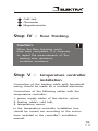
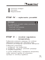
Step V – temperature controller
installation
Connection of the heating cable with household
wiring should be made by a certified electrician.
Connections of the following cables with the
temperature controller:
1. power supply cables of the electric system,
2. heating cable’s cold tails,
3. temperature sensor
in the temperature controller installation box,
should be carried out according to the instruc-
tions included in the controller’s installation
manual.

20
Caution:
The heating cable's earth cables (PE)
should be connected to the earth (yellow
and green) of the household wiring with
a special terminal on the temperature
controller.
If there is no such terminal on the tempe-
rature controller’s housing, the connection
should be made separately using a wire
connector which will be placed in the
installation box.
If several heating cables were installed in
the room, connect them in parallel, i.e.
cables with the same markings (the same
colour) should lead to the same terminals
on the temperature controller.
Heating Cables
ELEKTRA
Strona się ładuje...
Strona się ładuje...
Strona się ładuje...
Strona się ładuje...
Strona się ładuje...
Strona się ładuje...
Strona się ładuje...
Strona się ładuje...
Strona się ładuje...
Strona się ładuje...
Strona się ładuje...
Strona się ładuje...
Strona się ładuje...
Strona się ładuje...
Strona się ładuje...
Strona się ładuje...
Strona się ładuje...
Strona się ładuje...
Strona się ładuje...
Strona się ładuje...
Strona się ładuje...
Strona się ładuje...
Strona się ładuje...
Strona się ładuje...
Strona się ładuje...
Strona się ładuje...
Strona się ładuje...
Strona się ładuje...
Strona się ładuje...
Strona się ładuje...
Strona się ładuje...
Strona się ładuje...
Strona się ładuje...
Strona się ładuje...
Strona się ładuje...
Strona się ładuje...
Strona się ładuje...
Strona się ładuje...
Strona się ładuje...
Strona się ładuje...
Strona się ładuje...
Strona się ładuje...
Strona się ładuje...
Strona się ładuje...
Strona się ładuje...
Strona się ładuje...
Strona się ładuje...
Strona się ładuje...
Strona się ładuje...
Strona się ładuje...
Strona się ładuje...
Strona się ładuje...
Strona się ładuje...
Strona się ładuje...
Strona się ładuje...
Strona się ładuje...
Strona się ładuje...
Strona się ładuje...
Strona się ładuje...
Strona się ładuje...
Strona się ładuje...
Strona się ładuje...
Strona się ładuje...
Strona się ładuje...
-
 1
1
-
 2
2
-
 3
3
-
 4
4
-
 5
5
-
 6
6
-
 7
7
-
 8
8
-
 9
9
-
 10
10
-
 11
11
-
 12
12
-
 13
13
-
 14
14
-
 15
15
-
 16
16
-
 17
17
-
 18
18
-
 19
19
-
 20
20
-
 21
21
-
 22
22
-
 23
23
-
 24
24
-
 25
25
-
 26
26
-
 27
27
-
 28
28
-
 29
29
-
 30
30
-
 31
31
-
 32
32
-
 33
33
-
 34
34
-
 35
35
-
 36
36
-
 37
37
-
 38
38
-
 39
39
-
 40
40
-
 41
41
-
 42
42
-
 43
43
-
 44
44
-
 45
45
-
 46
46
-
 47
47
-
 48
48
-
 49
49
-
 50
50
-
 51
51
-
 52
52
-
 53
53
-
 54
54
-
 55
55
-
 56
56
-
 57
57
-
 58
58
-
 59
59
-
 60
60
-
 61
61
-
 62
62
-
 63
63
-
 64
64
-
 65
65
-
 66
66
-
 67
67
-
 68
68
-
 69
69
-
 70
70
-
 71
71
-
 72
72
-
 73
73
-
 74
74
-
 75
75
-
 76
76
-
 77
77
-
 78
78
-
 79
79
-
 80
80
-
 81
81
-
 82
82
-
 83
83
-
 84
84


ELEKTRA ELEKTRA UltraTec Instrukcja instalacji
- Typ
- Instrukcja instalacji
- Niniejsza instrukcja jest również odpowiednia dla
w innych językach
Powiązane artykuły
Inne dokumenty
-
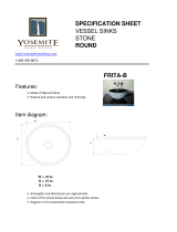 Yosemite Home Decor FRITA-B Instrukcja obsługi
-
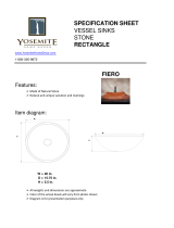 Yosemite Home Decor FIERO Instrukcja obsługi
-
STIEBEL ELTRON FTM 150-1050 B Operation Instruction
-
STIEBEL ELTRON FTM 150 B Instrukcja obsługi
-
Raychem EM-MI Instrukcja instalacji
-
-
Uponor Comfort E Cable Mat Instrukcja instalacji
-
OJ Electronics OTD2 Instrukcja obsługi
-
-
OJ Electronics OCD4 Instrukcja obsługi

