STIEBEL ELTRON FTM 150 B Instrukcja obsługi
- Typ
- Instrukcja obsługi

OPERATION AND INSTALLATION
OBSLUHA A INSTALACE
ЭКСПЛУАТАЦИЯ И УСТАНОВК А
OBSŁUGA I INSTALACJA
Floor tempering | Temperování podlahového topení | Система обогрева пола прямого
действия | Wyrównywanie temperatury podłogi
» FTM 150 B
» FTM 225 B
» FTM 300 B
» FTM 375 B
» FTM 450 B
» FTM 600 B
» FTM 750 B
» FTM 900 B
» FTM 1050 B

2 | FTM 150-1050 B www.stiebel-eltron.com
CONTENTS | SPECIAL INFORMATION
General information
SPECIAL INFORMATION
OPERATION
1. General information �����������������������������������������2
1.1 Safety instructions ����������������������������������������������� 2
1.2 Other symbols in this documentation ����������������������� 3
1.3 Information on the appliance ��������������������������������� 3
1.4 Units of measurement ������������������������������������������ 3
2. Safety ���������������������������������������������������������� 3
2.1 Intended use ������������������������������������������������������ 3
2.2 General safety instructions ������������������������������������ 3
2.3 Test symbols ������������������������������������������������������ 3
3. Settings �������������������������������������������������������3
4. Cleaning, care and maintenance ���������������������������3
5. Troubleshooting ����������������������������������������������4
INSTALLATION
6. Safety ���������������������������������������������������������� 4
6.1 General safety instructions ������������������������������������ 4
6.2 Instructions, standards and regulations �������������������� 4
7. Appliance description ���������������������������������������4
7.1 Standard delivery ������������������������������������������������ 4
7.2 Warranty card / installation diagram ������������������������ 4
8. Preparations ��������������������������������������������������4
8.1 Installation site / Installation conditions �������������������� 4
8.2 Safety clearances ������������������������������������������������ 5
8.3 Installation diagram ��������������������������������������������� 5
8.4 Test measurement 1 ��������������������������������������������� 6
8.5 Preparing the substrate ���������������������������������������� 6
9. Installation ����������������������������������������������������6
9.1 Installing a flush box �������������������������������������������� 6
9.2 Installing temperature sensors ������������������������������� 6
9.3 Installing the cold lead ����������������������������������������� 6
9.4 Laying out the heating mat ������������������������������������ 7
9.5 Test measurement 2 ��������������������������������������������� 7
9.6 Laying the floor covering ��������������������������������������� 7
9.7 Test measurement 3 ��������������������������������������������� 8
9.8 Power supply ����������������������������������������������������� 8
10. Commissioning �����������������������������������������������9
10.1 Initial start-up ���������������������������������������������������� 9
10.2 Commissioning report ������������������������������������������ 9
11. Handover ������������������������������������������������������9
12. Specification ��������������������������������������������������9
12.1 Data table ��������������������������������������������������������� 9
WARRANTY FOR AUSTRALIA
GUARANTEE
ENVIRONMENT AND RECYCLING
SPECIAL INFORMATION
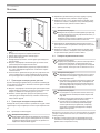
- The appliance may be used by children aged8
and up and persons with reduced physical, sen-
sory or mental capabilities or a lack of experience
and know-how, provided that they are supervised
or they have been instructed on how to use the
appliance safely and have understood the result-
ing risks. Children must never play with the ap-
pliance. Children must never clean the appliance
or perform user maintenance unless they are
supervised.
- The connection to the power supply must be in
the form of a permanent connection. Ensure the
appliance can be separated from the power sup-
ply by an isolator that disconnects all poles with
at least 3mm contact separation.
- The power cable must only be replaced by a
qualified contractor using original spare parts.
- Fix the appliance in position as described in
chapter "Installation/ Preparations".
OPERATION
1. General information
The chapters "Special Information" and "Operation" are intended
for both the user and qualified contractors.
The chapter "Installation" is intended for qualified contractors.
Note
Read these instructions carefully before using the appli-
ance and retain them for future reference.
Pass on the instructions to a new user if required.
1.1 Safety instructions
1.1.1 Structure of safety instructions
! KEYWORD Type of risk
Here, possible consequences are listed that may result
from failure to observe the safety instructions.
Steps to prevent the risk are listed.

OPERATION
Safety
www.stiebel-eltron.com FTM 150-1050 B| 3
ENGLISH
1.1.2 Symbols, type of risk
Symbol Type of risk
Injury
Electrocution
1.1.3 Keywords
KEYWORD Meaning
DANGER Failure to observe this information will result in serious
injury or death.
WARNING Failure to observe this information may result in serious
injury or death.
CAUTION Failure to observe this information may result in non-seri-
ous or minor injury.
1.2 Other symbols in this documentation
Note
General information is identified by the adjacent symbol.
Read these texts carefully.
Symbol Meaning
Material losses
(appliance damage, consequential losses and environmen-
tal pollution)
Appliance disposal
This symbol indicates that you have to do something. The ac-
tion you need to take is described step by step.
1.3 Information on the appliance
Symbol Meaning
Underfloor heating system (direct action)
1.4 Units of measurement
Note
All measurements are given in mm unless stated oth-
erwise.
2. Safety
2.1 Intended use
The heating mat provides direct underfloor heating and is used
for electric underfloor heating in individual areas, e.g. bathrooms,
kitchens, sauna lobbies, hallways or other living areas and in
indoor swimming pools and other wet rooms.
This appliance is intended for domestic use. It can be used safely
by untrained persons. The appliance can also be used in a non-do-
mestic environment, e.g. in a small business, as long as it is used
in the same way.
Any other use beyond that described shall be deemed inappropri-
ate. Observation of these instructions and of instructions for any
accessories used is also part of the correct use of this appliance.
2.2 General safety instructions
! WARNING Injury
The appliance may be used by children aged 8 and up and
persons with reduced physical, sensory or mental capa-
bilities or a lack of experience and know-how, provided
that they are supervised or they have been instructed on
how to use the appliance safely and have understood
the resulting risks. Children must never play with the
appliance. Children must never clean the appliance or
perform user maintenance unless they are supervised.
! Material losses
Only operate the heating mat when fully installed and
with all safety equipment fitted.
2.3 Test symbols
See type plate label, label on the warranty card or in the main
junction box.
3. Settings
You can set the required floor temperature by means of an external
temperature controller.
The floor temperature which can be achieved depends on the
floor structure and the floor covering. Observe the information
in the operating and installation instructions for the temperature
controller.
3.3.1 Temperature controller with time switch
Energy saving operation is ensured by installing a temperature
controller with time switch.
Using a temperature controller with time switch means that you
can adapt the heating operation to your lifestyle by specifying
when the heating mat will switch on and off.
Adjust the operating times so that it switches on a certain
amount of time before use. The necessary time depends on
the floor structure and the floor covering.
Adjust the time it switches off so that the appliance switches
off approximately half an hour before the end of use.
Further information can be found in the operating and installation
instructions for the temperature controller.
4. Cleaning, care and maintenance
The heating mat does not require any particular maintenance.
!
!

4 | FTM 150-1050 B www.stiebel-eltron.com
INSTALLATION
Troubleshooting
5. Troubleshooting
Problem Cause Remedy
The heating mat does not
provide the necessary
heating output.
The temperature control-
ler is not set correctly.
Adjust the temperature
controller to the maxi-
mum heating level. After
waiting for a short time,
check whether the floor
is warming up.
For temperature control-
lers with a time switch:
Operating times are not
set correctly.
Check the time switch
operating times and ad-
just if necessary.
There is no power.
Check whether the fuses/
MCBs in your fuse box
have blown/responded.
If you cannot remedy the fault, notify your qualified contractor.
To facilitate and speed up your request, provide the number from
the type plate (000000-0000-000000).
You will find the type plate on the warranty card in these instruc-
tions and in the main junction box.
INSTALLATION
6. Safety
Only a qualified contractor should carry out installation, commis-
sioning, maintenance and repair of the appliance.
6.1 General safety instructions
We guarantee trouble-free function and operational reliability only
if original accessories and spare parts intended for the appliance
are used.
6.2 Instructions, standards and regulations
! Material losses
Never install the heating mat on highly or normally flam-
mable materials.
! Material losses
Never switch on the heating mat when it is rolled up.
Note
Observe all applicable national and regional regulations
and instructions.
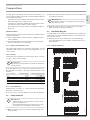
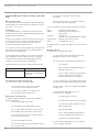
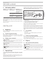
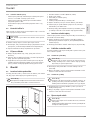
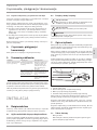
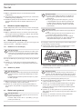
7. Appliance description
The heating mat is a surface heating element. The heating mat
comprises a heating conductor which is coiled over a self-adhesive
fabric.
The heating mat is glued directly to the screed or to levelling com-
pound (e.g. floating screed). The heat generated by the heating
mat is thus transferred directly to the floor.
The required floor temperature is set via an external tempera-
ture controller. The temperature controller is equipped with a
temperature sensor. The temperature sensor must be installed
at heating level.
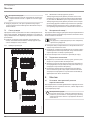
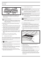
26�07�29�0100�
321
45
1 Heating conductor
2 Temperature sensors
3 Conduit (tube for installing the temperature sensor)
4 Female connection for heating conductor/cold lead
5 Cold lead (electrical power cable)
The heating mat is switched on or off according to the floor tem-
perature set on the temperature controller.
The temperature controller takes account of heat gain, e.g. due to
sunlight or lighting, and provides frost protection.
The temperature controller is self-monitoring. In the event of a
power failure, sensor break or sensor short-circuit, the heating
automatically switches off.
7.1 Standard delivery
- Heating mat
- Two type plate labels (warranty card / main junction box)
7.2 Warranty card / installation diagram
You must complete the warranty card and installation diagram
fully. The warranty is not valid without this proof.
The chapter “Preparations” contains information on completing
the installation diagram.
8. Preparations
8.1 Installation site / Installation conditions
! Material losses
Do not install the heating mat at temperatures below 5°C.
Note
In new builds, allow the screed to cure for 4-6 weeks.
Only install the heating mat once this period has ended.
8.1.1 Substrate
! Material losses
The heating mat may only be installed on floors. Walls or
ceilings may not be used as installation surfaces.

www.stiebel-eltron.com FTM 150-1050 B| 5
ENGLISH
INSTALLATION
Preparations
You may install the heating mat on a variety of substrates, e.g.
screed, hot mix asphalt or moisture-resistant chipboard. Observe
the following information:
- Installation on hot mix asphalt: The substrate must be able to
withstand temperatures of approx. 80°C.
- Installation on chipboard: Suitable insulation boards can also
be installed to improve impact sound insulation.
- Very sandy screed surfaces must be coated with an adhesive
dispersion.
Thermal insulation
Thermal insulation must be fitted between the unfinished floor
and the heating mat.
Please ensure that the thermal insulation complies with the
latest standards.
The maximum thermal resistance between the heating mat
and the room must not exceed 50mm.
8.1.2 Bathrooms and shower rooms
The heating mat must not be installed in areas where sanitary
equipment such as baths, showers, freestanding WCs, etc. are
to be installed.
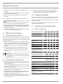
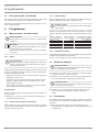
Floor coverings
The heating mat is suitable for use with a range of floor coverings,
e.g. tiles, carpets, PVC or parquet.
! Material losses
Only use floor coverings which are suitable for underfloor
heating systems.
Note that different floor coverings have different thermal con-
ductivity values according to their type and the thickness of the
material:
Floor covering Max. thickness Thermal conductivity
Tiles 30 mm λ = 1.00 W/(m · K)
Carpet 20 mm λ = 0.09 W/(m · K)
Parquet 16 mm λ = 0.14 W/(m · K)
PVC 10 mm λ = 0.23 W/(m · K)
Cork 10 mm λ = 0.08 W/(m · K)
8.1.3 Covering the floor
Additional floor coverings, e.g. carpets, may lead to higher tem-
peratures in the floor itself.
Do not use floor coverings which are more than 10mm thick.
8.2 Safety clearances
! Material losses
- Cupboards which cover the whole area must not be
placed on heated areas.
- The heating mat must not be installed close to other
heat sources such as luminaires and chimneys.
Make sure that you leave a 60cm wide unheated edge area
along the walls.
Make sure that you observe a distance of at least 30mm from
all conductive materials.
! Material losses
The heating conductors on heating mats installed in par-
allel must not touch.
Make sure that you observe a distance of at least 50mm
when installing heating mats in parallel.
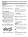
8.3 Installation diagram
You must draw up an installation diagram before installing the
heating mat. See chapter "Sample installations" and "Safety clear-
ances" in this respect.
Draw the position of the heating mats, the unheated edge
area, the temperature sensor and the cold lead on the instal-
lation diagram.
8.3.1 Sample installations
60 mm
60 mm
26�07�29�0014

6 | FTM 150-1050 B www.stiebel-eltron.com
INSTALLATION
Installation
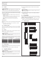
8.3.2 Position of the temperature sensor
- The temperature sensor must be positioned directly below
the heating mat and approx. 100 mm from the edge of the
heating mat.
- The temperature sensor must be positioned halfway between
two heating conductor loops.
- The temperature sensor lead must not cross or touch the
heating conductor.
8.4 Test measurement 1
Before installation, please check the total resistance and insulation
resistance of the heating mats in their delivered condition.
Note
The warranty is not valid without proof of this meas-
urement.
Measure the total resistance and insulation resistance of the
heating mat.
Check whether the measured values are in the permissible
measuring range (see chapter "Specification / Data table").
Enter the measured values on the warranty card.
8.5 Preparing the substrate
Make sure that the substrate is clean, dry, solid and free from
dirt and grease.
Make sure that no sharp edges or pointed objects are pro-
truding from the floor. These could damage the heating
conductor.
If the substrate is not level, carry out levelling operations so
as to avoid cavities beneath the heating conductor. Settle-
ment joints in the substrate must not be bridged using the
heating mat.
9. Installation
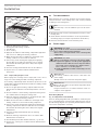
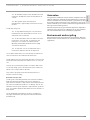
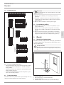
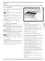
9.1 Installing a flush box
Please install all power cables in a flush box for connection to the
temperature controller.
! Material losses
In bathrooms and wet rooms, the flush box must only be
installed outside safety zone2.
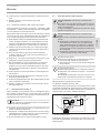
3
2
5
4
26�07�29�0009�
1
1 Distribution cable (NYM 3x1.5mm2)
2 Flush box
3 Conduit for temperature sensor
4 Temperature sensors
5 Cold lead / conduit for cold lead
Choose an appropriate position to install the flush box.
Install an additional flush box if you would like to connect
more heating mats.
Always install an additional flush box if the cold lead or tem-
perature sensor lead is too short.
9.2 Installing temperature sensors
The temperature sensor must be installed in a conduit. The conduit
is included as standard in the set.
Choose an appropriate position for installing the conduit.
Observe the instructions in chapter "Installation diagram /
Position of the temperature sensor".
Install the conduit and insert the temperature sensor into it.
9.3 Installing the cold lead
You can install the cold lead in a conduit or flush with the floor in
a groove in the screed.
9.3.1 Installing in a conduit
! Material losses
The cold lead must be installed in a separate conduit. The
cold lead and the temperature sensor lead must not be
installed in the same conduit.
Install an additional conduit and install the cold lead in the
conduit.
Make sure that the female connection for the heating con-
ductor/cold lead is not subjected to a tensile load of more
than 120N.

www.stiebel-eltron.com FTM 150-1050 B| 7
ENGLISH
INSTALLATION
Installation
9.3.2 Installation in the floor
! Material losses
If installed in the floor, the cold lead must be able to be
inserted in the flush box without an extension.
The cold lead may not cross or touch the heating con-
ductor.
Chisel out a groove in the screed by using appropriate tools
and install the cold lead in this groove.
Make sure that the female connection for the heating con-
ductor/cold lead is not subjected to a tensile load of more
than 120N.
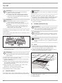
9.4 Laying out the heating mat
! Material losses
Do not cut, squash or kink the heating conductor on the
heating mat.
You may shorten and extend the cold lead as long as you
do not change its cross-section.
! Material losses
Do not use nails or other metal objects to attach the
heating mat to the floor.
Only stand on the heating mat if absolutely neces-
sary. Take any necessary protective measures to
avoid mechanical damage (e.g. shoes with rubber
soles).
! Material losses
Do not install the heating mat through or beneath
insulating material.
The installed heating mat may not cross expansion
joints in the floor.
Do not use penetrating fixing materials in the vicini-
ty of the heating mat, e.g. screws and rawl plugs for
door stoppers, WC fittings.
Observe the position of the heating mat specified in the installation
diagram for the subsequent steps.
Lay out the heating mat in accordance with the installation
diagram. The self-adhesive side must be facing downwards.
26�07�29�0094�
Cut the heating mat backing fabric with scissors at the turn-
ing point. Make sure that you don't accidentally damage the
heating conductor with the scissors.
! Material losses
The heating conductor bending radius must be at least
18mm. The smallest permissible bending radius is six
times the diameter of the heating conductor.
Carefully bend the heating conductor at the cutting point.
Observe minimum distances (see chapter "Preparations /
Safety clearances").
Make sure that the temperature sensor lead does not cross or
touch the heating conductor and that the temperature sensor
is halfway between two heating conductor loops.
Make sure that heating mats do not overlap. Overlapping
heating mats may lead to malfunctions.
Make sure that the fabric is laid out without any creases.
Press the heating mat firmly onto the floor.
9.5 Test measurement 2
After laying out the heating mat, check the total resistance and
insulation resistance of the heating mat to rule out the possibility
of damage to the heating mat.
Note
The warranty is not valid without proof of this meas-
urement.
Measure the total resistance and insulation resistance of the
heating mats.
Check whether the measured values are in the permissible
measuring range (see chapter "Specification / Data table").
Enter the measured values on the warranty card.
Replace the damaged heating mat if the measured values
deviate from the permissible range.
9.6 Laying the floor covering
! Material losses
Only use tile adhesive and levelling compound which are
suitable for underfloor heating systems and which can
withstand constant temperatures of at least 80°C.
! Material losses
When applying tile adhesive and levelling compound,
please observe the manufacturer's instructions concern-
ing drying time and other manufacturer's information.
Note
You must wait at least 3days, depending on the humidity
levels within the building, before starting to lay the floor
covering.
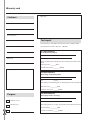
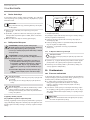
9.6.1 Tiles
Select an appropriate tile adhesive or levelling compound if
applicable. Note that this must be able to withstand constant
temperatures of at least 80°C.
Seal the conduits so that tile adhesive cannot get into the
conduits whilst installing the heating mats.

8 | FTM 150-1050 B www.stiebel-eltron.com
INSTALLATION
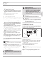
Installation
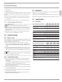
26�07�29�0004�
1
2
3
4
1 Substrate with thermal insulation
2 Heating mat with heating conductor
3 Tile adhesive
4 Floor covering
Apply the tile adhesive and levelling compound if applicable.
Take care not to damage the heating conductor.
Make sure that the entire circumference and length of the
heating conductor is enclosed in tile adhesive.
If necessary, lift the heating mat slightly after applying
the tile adhesive to make sure that there are no air bub-
bles beneath the heating mat. These may lead to higher
temperatures.
Press the heating mat back down into the tile adhesive.
Lay the tiles in accordance with the manufacturer's
instructions.
9.6.2 Carpet, PVC, parquet or cork
Before laying floor coverings such as carpet, PVC or cork, cover a
large area of the heating mat with a levelling compound.
The levelling compound provides mechanical protection for the
heating mats. Appropriate materials include free-flowing cement
mortar, for example.
Choose an appropriate levelling compound. Note that this
must be able to withstand constant temperatures of at least
80°C.
Seal the conduits so that levelling compound cannot get into
the conduits whilst installing the heating mats.
Apply the levelling compound in a 5-10mm thick layer. Take
care not to damage the heating conductor.
Make sure that the entire circumference and length of the
heating conductor is enclosed in levelling compound.
If necessary, lift the heating mat slightly after applying the
levelling compound to make sure that there are no air bub-
bles beneath the heating mat. These may lead to higher
temperatures.
Press the heating mat back down into the levelling
compound.
Allow the levelling compound to cure in accordance with
manufacturer's instructions.
Fill settlement joints with suitable materials, e.g. silicone.
Lay the floor covering in accordance with the manufacturer's
instructions.
9.7 Test measurement 3
After laying the floor covering, check the total resistance and in-
sulation resistance of the heating mat to rule out the possibility
of damage to the heating mats.
Note
The warranty is not valid without proof of this meas-
urement.
Measure the total resistance and insulation resistance of the
heating mats.
Check whether the measured values are in the permissible
measuring range (see chapter "Specification / Data table").
Enter the measured values on the warranty card.
9.8 Power supply
WARNING Electrocution
Carry out all electrical connection and installation work
in accordance with relevant regulations.
Observe the local requirements of the relevant power
supply utility.
WARNING Electrocution
Only use a permanent connection to the power supply.
Separate the appliance from the power supply by an
additional isolator that disconnects all poles with at
least 3mm contact separation. Use mains isolators,
fuses, contactors, etc. for this purpose.
Install an RCD with a nominal earth leakage current
of ≦30mA.
! Material losses
The heating conductor must not be connected to the
power supply.
Only connect the cold lead to the power supply.
! Material losses
Observe the type plate. The specified voltage must match
the mains voltage.
Design all materials in accordance with the rated con-
sumption of the appliance.
Basic wiring diagram
(e.g. for temperature controller RTF)
The basic wiring diagram below is provided for clarification pur-
poses. The temperature controller wiring diagram is the only ap-
plicable wiring diagram (see operating and installation instruc-
tions for the temperature controller).
FFL
LH
TA
N
RTF
L
N
26�07�21�0035
1
2

www.stiebel-eltron.com FTM 150-1050 B| 9
ENGLISH
INSTALLATION
Commissioning
1 Heating mat
2 Temperature sensors
In connection with the following installation steps, observe the
operating and installation instructions for the temperature con-
troller:
Connect the earth conductor to the earth connection (PE).
Connect the heating mats to the temperature controller via
the cold lead.
Check whether the earth conductor is connected correctly.
9.8.1 Connecting additional heating mats
! Material losses
Only connect additional heating mats in parallel.
Make sure that the total current does not exceed the maxi-
mum switching current and breaking capacity of the temper-
ature controller.
Information can be found in the operating and installation
instructions for the temperature controller.
10. Commissioning
10.1 Initial start-up
After installing the heating mat and applying tile adhesive or lev-
elling compound, you must wait at least 2days before switching
on the heating mat for the first time.
Switch on the heating mat for short periods over several
days once this initial drying phase has been completed. This
ensures that the tile adhesive and levelling compound cure
slowly.
If you have laid impermeable synthetic floor coverings, you
must heat the floor for a period of approx. 36hours. This en-
sures that there will be no residual humidity left in the floor.
Note
Final commissioning can take place no sooner than 5days
after completion of the floor.
10.2 Commissioning report
Make sure that you have completed the warranty card and
the installation diagram correctly. Observe the following
information:
- The installation diagram must show the exact position of the
heating mats, cold leads and temperature sensor.
- Measured values from all three test measurements must be
entered on the warranty card.
Enter the measured total resistance and insulation resistance
on both type plate labels.
Attach the type plate label for the warranty card to the speci-
fied position on this card.
Attach the type plate label for the main junction box in a
highly visible location on this box.
11. Handover
Explain the functions of the appliance to the user. Draw special
attention to the safety instructions.
Hand over these operating and installation instructions to the user.
Hand over the warranty card and installation diagram to the user.
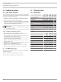
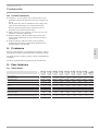
12. Specification
12.1 Data table
FTM
150B
FTM
225B
FTM
300B
FTM
375B
FTM
450B
234548 234549 234550 234551 234552
Electrical details
Connected load W135 220 300 380 470
Power supply
1/N/
PE ~
230 V
1/N/
PE ~
230 V
1/N/
PE ~
230 V
1/N/
PE ~
230 V
1/N/
PE ~
230 V
Electrical resistance (+10/-5%) Ω 351 236 164 147 105
Dimensions
Length mm 2000 3000 4000 5000 6000
Width mm 500 500 500 500 500
Surface m² 11,5 22,5 3
Versions
IP-Rating IPX7 IPX7 IPX7 IPX7 IPX7
Values
Rated limit temperature, heating
element
°C 80 80 80 80 80
FTM
600B
FTM
750 B
FTM
900B
FTM
1050B
234553 234554 234555 234556
Electrical details
Connected load W650 815 930 1040
Power supply 1/N/PE ~
230 V
1/N/PE ~
230 V
1/N/PE ~
230 V
1/N/PE ~
230 V
Electrical resistance (+10/-5%) Ω 87 67 55 48
Dimensions
Length mm 8000 10000 12000 14000
Width mm 500 500 500 500
Surface m² 4 5 6 7
Versions
IP-Rating IPX7 IPX7 IPX7 IPX7
Values
Rated limit temperature, heating
element
°C 80 80 80 80

10 | FTM 150-1050 B www.stiebel-eltron.com
WARRANTY FOR AUSTRALIA
Stiebel Eltron Warranty for Under Floor Heating – Models FTM
& FTB.
Who gives the warranty
1. The warranty is given by Stiebel Eltron (Aust) Pty Ltd (A.B.N.
82 066 271 083) of 6 Prohasky Street, Port Melbourne, Victoria,
3207 (“we”, “us” or “our”).
The warranty
2. This warranty applies to Stiebel Eltron under floor and in-
shower under floor heating – Models FTM and FTB (the “unit”)
manufactured after 1 May 2015.
3. Subject to the warranty exclusions we will repair or replace,
at our absolute discretion, a faulty component in your unit
free of charge if it fails to operate in accordance with its
specifications during the warranty period.
4. If we repair or replace a faulty component to your unit under
this warranty, the warranty period is not extended from the
time of the repair or replacement.
5. The warranty period commences on the date of completion
of the installation of the unit. Where the date of completion
of installation is not known, then the warranty period will
commence 2 months after the date of manufacture.
6. The warranty period for a unit is shown in the table below.
Component Warranty period
All components 7 years from the date of
completion of the installation
of the unit.
Your entitlement to make a warranty claim
7. You are entitled to make a warranty claim if:
7.1. you own the unit or if you have the owner’s
consent to represent the owner of the unit;
7.2. you contact us within a reasonable time of
discovering the problem with the unit;
How you make a warranty claim
8. To make a warranty claim you must provide us with the
following information:
8.1. The model number of the unit;
8.2. A description of the problem with the unit;
8.3. The name, address and contact details (such as
phone number and e-mail address) of the owner;
8.4. The address where the unit is installed and the
location (e.g. in living room);
8.5. The serial number of the unit;
8.6. The date of purchase of the unit and the name of
the seller of the unit;
8.7. The date of installation of the unit where
appropriate;
8.8. A copy of the certificate of compliance when the
unit was installed where appropriate.
9. The contact details for you to make your warranty claim are:
Name: Stiebel Eltron (Aust) Pty Ltd
Address: 6 Prohasky Street, Port Melbourne,
Victoria, 3207
Telephone: 1800 153 351
(8.00 am to 5.00 pm AEST Monday to Friday)
Contact person: Customer Service Representative
E-mail: service@stiebel.com.au
10. We will arrange a suitable time with you to inspect and test
the unit.
Warranty exclusions
11. We may reject your warranty claim if:
11.1. The unit was not installed by registered and
qualified tradespeople, where required.
11.2. The unit was not installed and commissioned:
(a) in Australia;
(b) in accordance with the Operating and
Installation Guide; and
(c) in accordance with the relevant statutory
and local requirements of the State or
Territory in which the unit is installed.
11.3. The unit has not been operated or maintained in
accordance with the Operating and Installation Guide.
11.4. The unit does not bear its original Serial Number
or Rating Label.
11.5. The unit was damaged by any or any
combination of the following:
(a) normal fair wear and tear;
(b) connection to an incorrect power supply;
(c) connection to faulty equipment, such as
faulty circuit breaker;
(d) accidental damage;
(e) act of God, including damage by flood,
storm, fire, lightning strike and the like;
(f) wiring not to AS3000 Standards
11.6. The unit was damaged before it was installed
e.g. it was damaged in transit.

www.stiebel-eltron.com FTM 150-1050 B| 11
ENGLISH
GUARANTEE | ENVIRONMENT AND RECYCLING
Guarantee
The guarantee conditions of our German companies do not
apply to appliances acquired outside of Germany. In countries
where our subsidiaries sell our products a guarantee can only
be issued by those subsidiaries. Such guarantee is only grant-
ed if the subsidiary has issued its own terms of guarantee. No
other guarantee will be granted.
We shall not provide any guarantee for appliances acquired in
countries where we have no subsidiary to sell our products.
This will not aect warranties issued by any importers.
Environment and recycling
We would ask you to help protect the environment. After use,
dispose of the various materials in accordance with national
regulations.
11.7. An unauthorised person has modified, serviced,
repaired or attempted to repair the unit without our
consent.
11.8. Non genuine parts other than those
manufactured or approved by us have been used on
the unit.
12. We may charge you:
12.1. for any additional transport costs if the unit is
installed more than 30 kilometres from our closest
authorised service technician.
12.2. for the extra time it takes our authorised service
technician to access the unit for inspection and
testing if it is not sited in accordance with the
Operating and Installation Guide and not readily
accessible for inspection.
12.3. for any extra costs of our authorised service
technician to make the unit safe for inspection.
13. You must ensure that access to the unit by our authorised
service technician is safe and free from obstruction.
14. Our authorised service technician may refuse to inspect and
test the unit until you provide safe and free access to it, at your
cost.
15. If we reject your warranty claim in accordance with clause
11, we may charge you for our authorised service technician’s
labour costs to inspect and test the unit.
16. In order to properly test the unit we may remove it to
another location for testing.
Australian Consumer Law
17. Our goods come with guarantees that cannot be excluded
under the Australian Consumer Law. You are entitled to a
replacement or refund for a major failure and compensation for
any other reasonably foreseeable loss or damage. You are also
entitled to have the goods repaired or replaced if the goods fail
to be of acceptable quality and the failure does not amount to a
major failure.
18. The Stiebel Eltron warranty for the unit is in addition to
any rights and remedies you may have under the Australian
Consumer Law.

12 | FTM 150-1050 B www.stiebel-eltron.com
NOTES

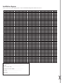
Warranty card
Customer
Purpose
Test report
This warranty is only valid if the warranty card is completed fully.
The insulation resistance must be > 1 M Ohm.
Type plate
Name
Street
Postcode/Town
Telephone
Customer
Electrician
Date laid
Date installed
Test measurement 1
(in the delivered condition)
Test measurement 2
(after laying out the heating mat)
Test measurement 3
(after laying the floor covering)
Date
Date
Date
Before installing the heating mat, the following values were meas-
ured:
After laying out the heating mat, the following values were measured:
After laying the floor covering, the following values were measured:
Total resistance ���������Ohm
Total resistance ����������� Ohm
Total resistance ����������� Ohm
Insulation resistance ���������� M Ohm
Insulation resistance ��������M Ohm
Insulation resistance ��������M Ohm
Signature
Signature
Signature
Company stamp
Cement screed
Wooden floor

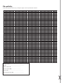
Installation diagram
Please create an accurate drawing of the room, the installed heating mats and the floor sensor.
1
1
2
3
4
5
6
7
8
9
10
11
12
13
14
15
16
17
18
19
20
21
22
23
24
25
26
27
28
29
30
31
32
33
34
35
36
37
38
39
40
2 3 4 5 6 7 8 9 10 11 12 13 14 15 16 17 18 19 20 21 22 23 24 25 26 27 28 29 30 31 32 33 34 35 36
Date installed: ............................................
Model: .................................................................
Total resistance (Ω): ...................................
Insulation resistance (MΩ): ................................
Fuse (A): ......................................................
RCD(mA): ....................................

www.stiebel-eltron.com FTM 150-1050 B | 15
ČESKY
OBSAH | ZVLÁŠTNÍ POKYNY
Obecné pokyny
ZVLÁŠTNÍ POKYNY
OBSLUHA
1. Obecné pokyny ��������������������������������������������� 15
1.1 Bezpečnostní pokyny ������������������������������������������ 15
1.2 Upozornění na přístroji ���������������������������������������� 16
1.3 Měrné jednotky ������������������������������������������������� 16
2. Bezpečnost �������������������������������������������������� 16
2.1 Použití vsouladu súčelem������������������������������������16
2.2 Všeobecné bezpečnostní pokyny ����������������������������16
2.3 Kontrolní symbol ������������������������������������������������ 16
3. Nastavení ��������������������������������������������������� 16
4. Čištění, péče a údržba ������������������������������������� 16
5. Odstranění problémů �������������������������������������� 17
INSTALACE
6. Bezpečnost �������������������������������������������������� 17
6.1 Všeobecné bezpečnostní pokyny ���������������������������� 17
6.2 Předpisy, normy a ustanovení ������������������������������� 17
7. Popis přístroje ���������������������������������������������� 17
7.1 Rozsah dodávky ������������������������������������������������� 17
7.2 Předávací protokol/plán pokládky ��������������������������� 17
8. Příprava ����������������������������������������������������� 17
8.1 Místo montáže/montážní podmínky ������������������������ 17
8.2 Bezpečné vzdálenosti ������������������������������������������ 18
8.3 Plán pokládky ��������������������������������������������������� 18
8.4 Kontrolní měření 1 ��������������������������������������������� 19
8.5 Příprava základu ������������������������������������������������ 19
9. Montហ������������������������������������������������������ 19
9.1 Instalace krabice pod omítku ��������������������������������� 19
9.2 Instalace snímače teploty ������������������������������������� 19
9.3 Pokládka studeného vodiče ����������������������������������� 19
9.4 Úprava topné rohože ������������������������������������������� 19
9.5 Kontrolní měření 2 ��������������������������������������������� 20
9.6 Pokládka podlahové krytiny ���������������������������������� 20
9.7 Kontrolní měření 3 ��������������������������������������������� 21
9.8 Elektrická přípojka ��������������������������������������������� 21
10. Uvedení do provozu ���������������������������������������� 22
10.1 První uvedení do provozu ������������������������������������� 22
10.2 Protokol o uvedení do provozu �������������������������������22
11. Předání přístroje ������������������������������������������� 22
12. Technické údaje �������������������������������������������� 22
12.1 Tabulka údajů ��������������������������������������������������� 22
ZÁRUKA
ŽIVOTNÍ PROSTŘEDÍ A RECYKLACE
ZVLÁŠTNÍ POKYNY
- Přístroj smí používat děti od 8let a osoby se sní-
ženými fyzickými, senzorickými nebo mentálními
schopnostmi nebo snedostatkem zkušeností a
znalostí pouze pod dozorem nebo po poučení
obezpečném používání přístroje, a poté, co po-
rozuměly nebezpečí, které zjeho používání plyne.
Nenechávejte děti, aby si spřístrojem hrály. Čiš-
tění a údržbu, kterou má provádět uživatel, nesmí
provádět samotné děti bez dozoru.
- Přípojka k elektrické síti smí být provedena pouze
jako pevná přípojka. Přístroj musí být možné od-
pojit odsíťové přípojky navšech pólech navzdá-
lenost nejméně 3mm.
- Přívodní síťový rozvod smí vpřípadě výměny
instalovat pouze kvalifikovaný elektrikář pomocí
originálních náhradních dílů.
- Upevněte přístroj způsobem popsaným vkapitole
„Instalace/ Příprava“.
OBSLUHA
1. Obecné pokyny
Kapitoly „Zvláštní pokyny“ a „Obsluha“ jsou určeny uživatelům
přístroje a instalačním technikům.
Kapitola „Instalace“ je určena instalačním technikům.
Upozornění
Dříve, než zahájíte provoz, si pozorně přečtěte tento
návod a pečlivě jej uschovejte.
Případně předejte návod dalšímu uživateli.
1.1 Bezpečnostní pokyny
1.1.1 Struktura bezpečnostních pokynů
! UVOZUJÍCÍ SLOVO - Druh nebezpečí
Zde jsou uvedeny možné následky nedodržení bezpeč-
nostních pokynů.
Zde jsou uvedena opatření kodvrácení nebezpečí.

OBSLUHA
Bezpečnost
16 | FTM 150-1050 B www.stiebel-eltron.com
1.1.2 Symboly, druh nebezpečí
Symbol Druh nebezpečí
Úraz
Úraz elektrickým proudem
1.1.3 Uvozující slova
UVOZUJÍCÍ
SLOVO
Význam
NEBEZPEČÍ Pokyny, jejichž nedodržení má za následek vážné nebo
smrtelné úrazy.
VÝSTRAHA Pokyny, jejichž nedodržení může mít za následek vážné
nebo smrtelné úrazy.
POZOR Pokyny, jejichž nedodržení může mít za následek středně
vážné nebo lehké úrazy.
1 Jiné symboly použité vtéto dokumentaci
Upozornění
Obecné pokyny jsou označeny symbolem zobrazeným
vedle.
Texty upozornění čtěte pečlivě.
Symbol Význam
Věcné škody
(poškození přístroje, následné škody, poškození životního
prostředí)
Likvidace přístroje
Tento symbol vás vyzývá kurčitému jednání. Potřebné úkony
jsou popsány po jednotlivých krocích.
1.2 Upozornění na přístroji
Symbol Význam
Podlahové topení (přímé)
1.3 Měrné jednotky
Upozornění
Pokud není uvedeno jinak, jsou všechny rozměry uvedeny
vmilimetrech.
2. Bezpečnost
2.1 Použití vsouladu súčelem
Topná rohož je přímé podlahové topení a slouží ktemperování
podlahy vjednotlivých zónách, např. vkoupelnách, kuchyních,
vstupních prostorách saun, na chodbách nebo vjiných oblastech
bytu, ale i vzastřešených plaveckých bazénech a vjiných vlhkých
prostorách.
Přístroj je určen kpoužití vdomácnostech. Mohou jej tedy bezpeč-
ně obsluhovat neškolené osoby. Lze jej používat i mimo domác-
nosti, např. v drobném průmyslu, pokud způsob použití v takových
oblastech odpovídá určení přístroje.
Jiné použití nebo použití nad rámec daného rozsahu je považová-
no za použití vrozporu surčením. Kpoužití vsouladu surčením
patří také dodržování tohoto návodu a návodů kpoužívanému
příslušenství.
2.2 Všeobecné bezpečnostní pokyny
! VÝSTRAHA úraz
Přístroj smí používat děti od 8let a osoby se sníženými
fyzickými, senzorickými nebo mentálními schopnostmi
nebo snedostatkem zkušeností a znalostí pouze pod do-
zorem nebo po poučení obezpečném používání přístroje,
a poté, co porozuměly nebezpečí, které zjeho používání
plyne. Nenechávejte děti, aby si spřístrojem hrály. Čiště-
ní a údržbu, kterou má provádět uživatel, nesmí provádět
samotné děti bez dozoru.
! Věcné škody
Topnou rohož používejte pouze vplně nainstalovaném
stavu a se všemi bezpečnostními zařízeními.
2.3 Kontrolní symbol
Viz nálepka stypovým štítkem, nálepka napředávacím protokolu
nebo nahlavní připojovací skříňce.
3. Nastavení
Požadovanou teplotu podlahy můžete nastavit pomocí externího
regulátoru teploty.
Dosažitelná teplota podlahy závisí na konstrukci podlahy a její
krytině. Dodržujte pokyny uvedené vnávodu kobsluze a instalaci
regulátoru teploty.
3.3.1 Regulátor teploty se spínacími hodinami
Instalace regulátoru teploty se spínacími hodinami umožňuje
energeticky úsporný provoz.
Regulací teploty spínacími hodinami můžete upravit topný režim
podle svých zvyklostí nastavením doby zapnutí a vypnutí topné
rohože.
Provozní doby nastavte tak, aby došlo kzapnutí systému
oněco dříve, než proběhne vlastní použití. Jak dlouhá tato
doba bude závisí na konstrukci podlahy a na podlahové
krytině.
Nastavte dobu vypnutí tak, aby byl systém vypnut zhruba půl
hodiny před koncem použití.
Další informace naleznete vnávodu kobsluze a instalaci regulá-
toru teploty.
4. Čištění, péče a údržba
Topná rohož nevyžaduje žádnou zvláštní údržbu.
!
!

www.stiebel-eltron.com FTM 150-1050 B | 17
ČESKY
INSTALACE
Odstranění problémů
5. Odstranění problémů
Problém Příčina Odstranění
Topná rohož nemá poža-
dovaný topný výkon.
Regulátor teploty není
správně nastavený.
Nastavte na regulátoru
teploty maximální topný
stupeň. Zkontrolujte po
určité době, zda se pod-
laha zahřívá.
Při použití regulátorů
teploty sčasovým spína-
čem: Nesprávně nastave-
né provozní doby.
Zkontrolujte provozní
doby časového spínače a
případně je upravte.
Došlo kvýpadku elektric-
kého napájení.
Zkontrolujte, zda nevy-
padly pojistky domovní
instalace.
Pokud nelze příčinu odstranit, kontaktujte odborníka. Kzískání
lepší a rychlejší pomoci sdělte číslo ztypového štítku (000000-
0000-000000).
Typový štítek naleznete na záruční kartě vtomto návodu a vhlavní
připojovací skříňce.
INSTALACE
6. Bezpečnost
Instalaci, uvedení do provozu, údržbu a opravy přístroje smí pro-
vádět pouze odborník.
6.1 Všeobecné bezpečnostní pokyny
Řádnou funkci a spolehlivý provoz lze zaručit pouze vpřípadě
použití původního příslušenství a originálních náhradních dílů
určených pro tento přístroj.
6.2 Předpisy, normy a ustanovení
! Věcné škody
Topnou rohož se nesmí pokládat nasnadno hořlavé nebo
hořlavé stavební materiály.
! Věcné škody
Topnou rohož nesmíte uvést do provozu, pokud je sro-
lovaná.
Upozornění
Dodržujte všechny národní a místní předpisy a ustano-
vení.
7. Popis přístroje
Topná rohož je plochý topný prvek. Topná rohož je provedena
ztopných kabelů, které jsou vedeny vesmyčkách vsamolepicí
tkanině.
Topná rohož je lepena přímo na cementový potěr nebo na nive-
lační hmotu (např. litý potěr). Teplo, které vytváří topná rohož, je
tak přenášeno bezprostředně na podlahu.
Požadovaná teplota podlahy je nastavena pomocí externího re-
gulátoru teploty. Regulátor teploty je vybaven snímačem teploty.
Snímač teploty musí být instalován do topné vrstvy.
26�07�29�0100�
321
45
1 Topný kabel
2 Snímač teploty
3 Průchodka (instalační trubka pro snímač teploty)
4 Spojovací článek topného/studeného kabelu
5 Studený kabel (přívodní elektrické vedení)
Topná rohož je zapínána nebo vypínána vzávislosti na teplotě
podlahy, nastavené na regulátoru teploty.
Regulátor teploty bere vúvahy tepelné zisky vznikající např. ozáře-
ním sluncem nebo osvětlením a zajišťuje kontrolu proti zamrznutí.
Regulátor teploty má autodiagnostickou funkci. Vpřípadě výpadku
napětí, poškození nebo zkratu snímače se vytápění automaticky
vypne.
7.1 Rozsah dodávky
- Topná rohož
- Dvě nálepky stypovým štítkem (předávací protokol/hlavní
připojovací skříňka)
7.2 Předávací protokol/plán pokládky
Předávací protokol a plán pokládky musíte kompletně vyplnit. Bez
tohoto dokladu nelze uplatnit záruku.
Pokyny kvyplnění plánu pokládky naleznete vkapitole „Přípravy“.
8. Příprava
8.1 Místo montáže/montážní podmínky
! Věcné škody
Topnou rohož nesmíte montovat za teploty nižší než 5°C.
Upozornění
Vnovostavbách musíte upotěrů dodržet dobu schnutí
4-6 týdnů.
Instalujte topnou rohož až po uplynutí této lhůty.

18 | FTM 150-1050 B www.stiebel-eltron.com
INSTALACE
Příprava
8.1.1 Podklad
! Věcné škody
Topnou rohož smíte pokládat pouze na podlahu. Stěny
nebo stropy se nesmí používat jako montážní plochy.
Topnou rohož můžete položit na různý podklad, např. potěr, horký
asfalt nebo na dřevotřískové desky odolné proti vodě. Dodržujte
jiné následující pokyny:
- Pokládka na horký asfalt: Podklad musí být odolný vůči tep-
lotám do cca 80°C.
- Pokládka na dřevotřískové desky: Kdosažení lepší kročejové
izolace můžete navíc použít vhodné izolační desky.
- Výrazně drolivé potěry musejí být ošetřeny přilnavou
disperzí.
Tepelná izolace
Mezi hrubou podlahou a topnou rohoží musí být umístěna tepelná
izolace.
Zkontrolujte, zda je tepelná izolace provedena vsouladu
saktuálním stavem techniky.
8.1.2 Koupelny a sprchy
Topnou rohož nesmíte pokládat na plochy, které jsou potřebné
kmontáži sanitárního vybavení, jako jsou vana, sprcha, záchodová
mísa apod.
8.1.3 Krytiny
Topná rohož je vhodná kpoužití na různých krytinách, např. na
dlažbě, koberci, PVC nebo na parketách.
! Věcné škody
Používejte pouze takové podlahové krytiny, které jsou
vhodné pro podlahové topení.
Pamatujte, že různé podlahové krytiny mají vzávislosti na typu a
tloušťce materiálů různou tepelnou vodivost:
Podlahová krytina Max. tloušťka Tepelná vodivost
Dlažba 30 mm λ = 1,00 W/(m · K)
Koberce 20 mm λ = 0,09 W/(m · K)
Parkety 16 mm λ = 0,14 W/(m · K)
PVC 10 mm λ = 0,23 W/(m · K)
Korek 10 mm λ = 0,08 W/(m · K)
8.1.4 Zakrytí podlahy
Dalším zakrytím podlahy např. koberci může dojít ke vzniku vyš-
ších teplot vpodlaze.
Nepoužívejte žádné zakrytí otloušťce více než 10mm.
8.2 Bezpečné vzdálenosti
! Věcné škody
Skříně sdnem položeným přímo na zemi smíte umístit
pouze na nevytápěná místa.
Dbejte, aby podél stěn zůstala nevytápěná plocha ošířce
60cm.
Zajistěte minimální vzdálenost 30mm ode všech vodivých
materiálů.
! Věcné škody
Topné kabely paralelně položených topných rohoží se
nesmějí dotýkat.
Při paralelní pokládce topných rohoží dodržujte minimální
vzdálenost 50mm.
8.3 Plán pokládky
Před zahájením montáže topné rohože musíte vytvořit plán po-
kládky. Dodržujte také pokyny uvedené vkapitolách „Příklady
pokládky“ a „Bezpečnostní vzdálenosti“.
Vyznačte ve schématu pokládky pozici topných rohoží, nevy-
hřívané okrajové zóny, snímače teploty a studeného kabel.
8.3.1 Příklady pokládky
60 mm
60 mm
26�07�29�0014

www.stiebel-eltron.com FTM 150-1050 B | 19
ČESKY
INSTALACE
Montáž
8.3.2 Umístění snímače teploty
- Snímač teploty musí být umístěn bezprostředně pod topnou
rohoží a cca100mm od okraje topné rohože.
- Snímač teploty musí být umístěn uprostřed mezi dvěma
smyčkami topného vodiče.
- Vodič snímače teploty nesmí křížit topný kabel nebo se jej
dotýkat.
8.4 Kontrolní měření 1
Před montáží je nutné zkontrolovat kompletní odpor a izolační
odpor topných rohoží při dodání.
Upozornění
Bez dokladu oprovedení tohoto měření nelze uplatnit
záruku.
Změřte celkový odpor a izolační odpor topné rohože.
Zkontrolujte, zda jsou měřené hodnoty vpřípustném rozsahu
(viz kapitola „Technické údaje/Tabulka technických údajů“).
Zapište naměřené hodnoty do předávacího protokolu.
8.5 Příprava základu
Dbejte, aby byl základ čistý, suchý, pevný, bez nečistot a
mastnoty.
Zajistěte, aby zpodlahy nevyčnívaly ostré nebo špičaté před-
měty. Ty mohou poškodit topný vodič.
Vpřípadě nerovností proveďte nivelační práce tak, aby pod
topným vodičem nezůstávaly prázdné prostory. Vyrovnávací
spáry vpodlaze nesmějí být přemosťovány topnou rohoží.
9. Montáž
9.1 Instalace krabice pod omítku
Všechny přívodní vodiče je nutné zavést do krabice pod omítku
tak, aby je bylo možné připojit kregulátoru teploty.
! Věcné škody
Vkoupelnách a vlhkých místnostech smíte instalovat kra-
bici pod omítku pouze mimo ochrannou oblast 2.
3
2
5
4
26�07�29�0009�
1
1 Přívodní vedení krozvaděči (NYM 3x1,5mm2)
2 Krabice pod omítku
3 Průchodka pro snímač teploty
4 Snímač teploty
5 Studený vodič/průchodka pro studený vodič
Vyberte vhodnou pozici pro instalaci krabice pod omítku.
Pokud si přejete použít několik topných rohoží, instalujte
další krabici pod omítku navíc.
Instalujte vždy jednu doplňkovou krabici pod omítku, pokud
je studený vodič nebo vodič snímače teploty příliš krátký.
9.2 Instalace snímače teploty
Snímač teploty musíte instalovat do průchodky. Ve variantě Set je
průchodka součástí dodávky.
Vyberte vhodnou pozici kinstalaci průchodky. Dodržujte
přitom pokyny uvedené vkapitole „Plán pokládky/umístění
snímače teploty“.
Instalujte průchodku a zaveďte snímač teploty do průchodky.
9.3 Pokládka studeného vodiče
Instalujte studený vodič do průchodky nebo vjedné rovině spod-
lahou vdrážce vpotěru.
9.3.1 Instalace do průchodky
! Věcné škody
Studený vodič je nutné instalovat do samostatné prů-
chodky. Studený vodič a vodič snímače teploty nesmějí
být vedeny ve společné průchodce.
Nainstalujte další průchodku a zaveďte studený vodič do
průchodky.
Dbejte, aby nebylo spojovací hrdlo teplého/studeného vodiče
zatíženo vtahu silou větší než 120N.
9.3.2 Instalace do podlahy
! Věcné škody
Studený vodič musí být možné vpřípadě instalace do
podlahy zavést bez prodloužení do krabice pod omítku.
Studený vodič nesmí křížit topný kabel, ani se jej dotýkat.
Vhodnými nástroji vysekejte drážku vpotěru a položte do
drážky studený vodič.
Dbejte, aby nebylo spojovací hrdlo teplého/studeného vodiče
zatíženo vtahu silou větší než 120N.
9.4 Úprava topné rohože
! Věcné škody
Topné vodiče topné rohože nesmíte zkracovat, zalamovat
nebo přivřít.
Studený vodič můžete zkrátit nebo nastavit, pokud přitom
nedojde kezměně průřezu.

20 | FTM 150-1050 B www.stiebel-eltron.com
INSTALACE
Montáž
! Věcné škody
Kupevnění topné rohože kpodlaze nepoužívejte
hřebíky a jiné kovové předměty.
Na topnou rohož smíte stoupnout, pouze pokud je
to nezbytně nutné. Proveďte případná preventivní
opatření proti mechanickému poškození (např. obuv
sgumovými podrážkami).
! Věcné škody
Nepokládejte topnou rohož do izolačního nebo te-
pelně izolačního materiálu nebo pod něj.
Instalovaná topná rohož nesmí křížit dilatační spáry
vpodlaze.
Neinstalujte voblasti topné rohože žádný průchozí
spojovací materiál, např. šrouby shmoždinkou pro
dveřní zarážku, upevnění mísy WC.
Unásledujících kroků dodržujte pozice topné rohože uvedené
vplánu instalace.
Položte topnou rohož podle plánu instalace. Samolepicí strana
musí směřovat dolů.
26�07�29�0094�
Odstřihněte nůžkami vmístě ohybu nosnou textilii topné
rohože. Dávejte přitom pozor, abyste nůžkami nedopatřením
nepoškodili topný vodič.
! Věcné škody
Poloměr ohybu topného kabel musí být nejméně 18mm.
Nejmenší přípustný poloměr ohybu je 6násobek průměru
topného kabelu.
Vmístě střihu topný vodič opatrně ohněte.
Dodržujte minimální vzdálenosti (viz kapitola „Příprava/bez-
pečnostní vzdálenosti).
Zajistěte, aby vodič snímače teploty nekřížil topný kabel ani
se jej nedotýkal, a umístěte teplotní snímač uprostřed mezi
dvě smyčky topného kabelu.
Dbejte, aby topné rohože neležely na sobě. Topné rohože
umístěné nasobě mohou způsobit závady.
Zkontrolujte, zda je tkanina položena bez ohybů.
Pevně přitlačte topnou rohož kpodlaze.
9.5 Kontrolní měření 2
Po rozložení topné rohože je nutné zkontrolovat celkový odpor a
izolační odpor topné rohože, vyloučíte tak poškození topné rohože.
Upozornění
Bez dokladu oprovedení tohoto měření nelze uplatnit
záruku.
Změřte celkový odpor a izolační odpor topných rohoží.
Zkontrolujte, zda jsou měřené hodnoty vpřípustném rozsahu
(viz kapitola „Technické údaje/Tabulka technických údajů“).
Zapište naměřené hodnoty do předávacího protokolu.
Při zjištění odchylek vnaměřených hodnotách poškozenou
topnou rohož vyměňte.
9.6 Pokládka podlahové krytiny
! Věcné škody
Používejte pouze lepidlo na obklady a nivelační hmotu,
které jsou vhodné pro podlahová topení a které mají tr-
valou odolnost proti teplotám minimálně 80°C.
! Věcné škody
Dodržujte při nanášení lepidla na obklady a nivelační
hmoty údaje výrobce odobě schnutí a další údaje vý-
robce.
Upozornění
Vzávislosti na vlhkosti vobjektu musíte minimálně 3dny
počkat, než budete moci začít spokládkou podlahové
krytiny.
9.6.1 Dlažba
Vyberte vhodné lepidlo na dlažbu nebo případně vhodnou
nivelační hmotu. Pamatujte, že materiály musejí být odolné
proti trvalému tepelnému zatížení minimálně 80°C.
Uzavřete průchodky, aby se při pokládce topných rohoží ne-
dostalo do průchodek žádné lepidlo na dlažbu.
26�07�29�0004�
1
2
3
4
1 Podklad stepelnou izolací
2 Topná rohož stopným vodičem
3 Lepidlo na dlažbu
4 Podlahová krytina
Strona się ładuje...
Strona się ładuje...
Strona się ładuje...
Strona się ładuje...
Strona się ładuje...
Strona się ładuje...
Strona się ładuje...
Strona się ładuje...
Strona się ładuje...
Strona się ładuje...
Strona się ładuje...
Strona się ładuje...
Strona się ładuje...
Strona się ładuje...
Strona się ładuje...
Strona się ładuje...
Strona się ładuje...
Strona się ładuje...
Strona się ładuje...
Strona się ładuje...
Strona się ładuje...
Strona się ładuje...
Strona się ładuje...
Strona się ładuje...
Strona się ładuje...
Strona się ładuje...
Strona się ładuje...
Strona się ładuje...
Strona się ładuje...
Strona się ładuje...
Strona się ładuje...
Strona się ładuje...
-
 1
1
-
 2
2
-
 3
3
-
 4
4
-
 5
5
-
 6
6
-
 7
7
-
 8
8
-
 9
9
-
 10
10
-
 11
11
-
 12
12
-
 13
13
-
 14
14
-
 15
15
-
 16
16
-
 17
17
-
 18
18
-
 19
19
-
 20
20
-
 21
21
-
 22
22
-
 23
23
-
 24
24
-
 25
25
-
 26
26
-
 27
27
-
 28
28
-
 29
29
-
 30
30
-
 31
31
-
 32
32
-
 33
33
-
 34
34
-
 35
35
-
 36
36
-
 37
37
-
 38
38
-
 39
39
-
 40
40
-
 41
41
-
 42
42
-
 43
43
-
 44
44
-
 45
45
-
 46
46
-
 47
47
-
 48
48
-
 49
49
-
 50
50
-
 51
51
-
 52
52


STIEBEL ELTRON FTM 150 B Instrukcja obsługi
- Typ
- Instrukcja obsługi
w innych językach
- slovenčina: STIEBEL ELTRON FTM 150 B Používateľská príručka