STIEBEL ELTRON PHB 13-24 Operation Instruction
- Typ
- Operation Instruction

OPERATION AND INSTALLATION
OBSLUHA A INSTALACE
OBSŁUGA I INSTALACJA
ОБСЛУЖВАНЕ И ИНСТАЛИРАНЕ
ЭКСПЛУАТАЦИЯ И УСТАНОВКА
Hydraulically controlled instantaneous water heater| Hydraulicky řízené průtokové ohřívače|
Hydraulicznie sterowany przepływowy ogrzewacz wody | Хидравлично контролиран проточен
бойлер | Проточный водонагреватель с гидравлическим управлением |
» PHB 13
» PHB 18
» PHB 21
» PHB 24
Made in Germany

2 | PHB 13-24 www.stiebel-eltron.com
CONTENTS | SPECIAL INFORMATION
SPECIAL INFORMATION
OPERATION
1. General information ������������������������������������������3
1.1 Safety instructions ����������������������������������������������� 3
1.2 Other symbols in this documentation ������������������������ 3
1.3 Units of measurement ������������������������������������������ 3
2. Safety ����������������������������������������������������������4
2.1 Intended use ������������������������������������������������������ 4
2.2 General safety instructions ������������������������������������� 4
2.3 Test symbols ������������������������������������������������������ 4
3. Appliance description ����������������������������������������4
4. Settings �������������������������������������������������������� 4
4.1 Recommended tap/valve settings ����������������������������� 5
5. Cleaning, care and maintenance ����������������������������5
6. Troubleshooting ����������������������������������������������5
INSTALLATION
7. Safety ����������������������������������������������������������6
7.1 General safety instructions ������������������������������������� 6
7.2 Instructions, standards and regulations ��������������������� 6
8. Appliance description ����������������������������������������6
8.1 Standard delivery ������������������������������������������������ 6
9. Preparations ��������������������������������������������������6
9.1 Installation site ��������������������������������������������������� 6
9.2 Water installation ������������������������������������������������ 7
10. Installation ����������������������������������������������������7
10.1 Standard installation �������������������������������������������� 7
10.2 Installation options ���������������������������������������������10
10.3 Completing the installation �����������������������������������11
11. Commissioning ��������������������������������������������� 11
11.1 Initial start-up ���������������������������������������������������11
11.2 Recommissioning ����������������������������������������������� 12
12. Shutdown ��������������������������������������������������� 12
13. Troubleshooting �������������������������������������������� 12
14. Maintenance ������������������������������������������������ 12
15. Specification ������������������������������������������������ 12
15.1 Dimensions and connections ��������������������������������� 12
15.2 Wiring diagram �������������������������������������������������� 13
15.3 DHW output ������������������������������������������������������ 13
15.4 Application areas/ conversion table ������������������������13
15.5 Pressure drop ���������������������������������������������������� 14
15.6 Fault conditions �������������������������������������������������14
15.7 Details on energy consumption ������������������������������14
15.8 Data table ��������������������������������������������������������15
GUARANTEE
ENVIRONMENT AND RECYCLING
SPECIAL
INFORMATION
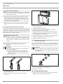
- The appliance may be used by children aged 3
and up and persons with reduced physical, sen-
sory or mental capabilities or a lack of experience
and know-how, provided that they are supervised
or they have been instructed on how to use the
appliance safely and have understood the result-
ing risks. Children must never play with the ap-
pliance. Children must never clean the appliance
or perform user maintenance unless they are
supervised.
- During operation, the tap can reach temperatures
in excess of 60 °C. There is a risk of scalding at
outlet temperatures in excess of 43°C.
- Ensure the appliance can be separated from the
power supply by an isolator that disconnects all
poles with at least 3mm contact separation.
- The specified voltage must match the mains
voltage.
- Connect the appliance to earth.
- Connect the appliance permanently to fixed
wiring.
- Secure the appliance as described in chapter
“Installation”.
- Observe the maximum permissible pressure
(see chapter “Installation/ Specification/ Data
table”).
- The specific water resistance of the water supply
mains must not be exceeded (see chapter “Instal-
lation/ Specification/ Data table”).
- Drain the appliance as described in chap-
ter “Installation/ Maintenance/ Draining the
appliance”.
- This appliance is not approved for reheating pre-
heated water.

OPERATION
General information
www.stiebel-eltron.com PHB 13-24| 3
ENGLISH
OPERATION
1. General information
The chapters "Special Information" and "Operation" are intended
for both the user and qualified contractors.
The chapter "Installation" is intended for qualified contractors.
Note
Read these instructions carefully before using the appli-
ance and retain them for future reference.
Pass on the instructions to any new user where appro-
priate.
1.1 Safety instructions
1.1.1 Structure of safety instructions
!
KEYWORD Type of risk
Here, possible consequences are listed that may result
from failure to observe the safety instructions.
Steps to prevent the risk are listed.
1.1.2 Symbols, type of risk
Symbol Type of risk
Injury
Electrocution
Burns
(burns, scalding)
1.1.3 Keywords
KEYWORD Meaning
DANGER Failure to observe this information will result in serious in-
jury or death.
WARNING Failure to observe this information may result in serious
injury or death.
CAUTION Failure to observe this information may result in non-serious
or minor injury.
1.2 Other symbols in this documentation
Note
General information is identified by the adjacent symbol.
Read these texts carefully.
Symbol Meaning
Material losses
(appliance damage, consequential losses and environmental
pollution)
Appliance disposal
This symbol indicates that you have to do something. The ac-
tion you need to take is described step by step.
1.3 Units of measurement
Note
All measurements are given in mm unless stated other-
wise.
!
!

OPERATION
Safety
4 | PHB 13-24 www.stiebel-eltron.com
2. Safety
2.1 Intended use
This appliance is intended for domestic use. It can be used safely
by untrained persons. The appliance can also be used in a non-do-
mestic environment, e.g.in a small business, as long as it is used
in the same way.
This pressure appliance is designed to heat DHW. The appliance
can supply one or more draw-off points.
Any other use beyond that described shall be deemed inappropri-
ate. Observation of these instructions and of instructions for any
accessories used is also part of the correct use of this appliance.
Note
The appliance is not approved for reheating preheated
water.
2.2 General safety instructions
CAUTION Burns
During operation, the tap can reach temperatures in ex-
cess of 60 °C.
There is a risk of scalding at outlet temperatures in excess
of 43°C.
!
WARNING Injury
The appliance may be used by children aged3 and up and
persons with reduced physical, sensory or mental capa-
bilities or a lack of experience and know-how, provided
that they are supervised or they have been instructed on
how to use the appliance safely and have understood the
resulting risks. Children must never play with the appli-
ance. Children must never clean the appliance or perform
user maintenance unless they are supervised.
!
Material losses
The user should protect the appliance and its tap against
frost.
2.3 Test symbols
See type plate on the appliance.
3. Appliance description
The hydraulically controlled instantaneous water heater heats the
water as it flows through the appliance. The heating output starts
automatically as soon as a tap is opened and the starting flow rate
is exceeded (see chapter "Specification/ Data table"). The water
volume and temperature can be adjusted at the tap.
You can choose between 2 output stages. Two further output stages
are hydraulically controlled in relation to the flow rate.
The flow rate controller compensates for pressure fluctuations,
thereby ensuring largely stable temperatures. The controller lim-
its the throughput, thereby ensuring an adequate increase in the
DHW temperature at all times.
Heating system
The bare wire heating system has a pressure-tested plastic casing.
The heating system is suitable for hard and soft water areas and is
largely insusceptible to scale build-up. This heating system ensures
rapid and efficient DHW availability.
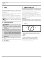
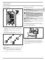
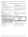
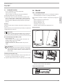
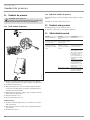
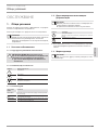
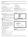
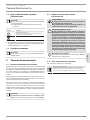
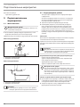
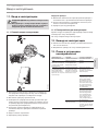
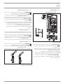
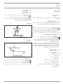
4. Settings
D0000041612
2 1
1 Partial load
At low throughput 1/3 of the heating output is activated; at
higher throughput 2/3 of the available heating output is ena-
bled. This setting is suitable for hand washing at a basin, for
example.
2 Full load
At a low throughput, 1/2 of the heating output is applied; at
a higher throughput the full heating output is activated. This
setting is suitable for washing dishes, for example.
Click the output selector into the required position.
Recommended settings when using a thermostatic valve
Set the output selector to full power.

OPERATION
Cleaning, care and maintenance
www.stiebel-eltron.com PHB 13-24| 5
ENGLISH
4.1 Recommended tap/valve settings
Note
If the outlet temperature is not sufficiently high at full load
and with the draw-off valve fully open, then more water is
flowing through the appliance than can be heated by the
heating system (appliance is at its output limit).
Reduce the water volume at the draw-off valve.
Low draw-off volume = High outlet temperature
High draw-off volume = Low outlet temperature
Twin lever tap
Output stage Application range
Partial load Washbasin
Full load Bath, shower, sink
Add cold water if the temperature is too high when the tap is
fully open.
Mono lever mixer
Output stage Application range
Full load All
Turn the tap lever to the highest temperature.
Fully open the tap.
Increase the outlet temperature by closing the tap slowly.
Reduce the outlet temperature by adding cold water or open-
ing the tap further, if possible.
Following an interruption to the water supply
!
Material losses
Following an interruption of the water supply the appli-
ance must be recommissioned by carrying out the follow-
ing steps, in order to prevent the destruction of the bare
wire heating system.
Disconnect the appliance from the power supply by
removing the fuses/tripping the MCBs.
Open the tap for one minute until the appliance and
its upstream cold water inlet line are free of air.
Switch the mains power back ON again.
5. Cleaning, care and maintenance
Never use abrasive or corrosive cleaning agents. A damp cloth
is sufficient for cleaning the appliance.
Check the taps regularly. Limescale deposits at the tap out-
lets can be removed using commercially available descaling
agents.
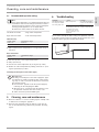
6. Troubleshooting
Problem Cause Remedy
The appliance will not
start despite the DHW
valve being fully open.
There is no power.
Check the fuses/MCBs in
your fuse box/distribution
panel.
The flow rate is too low
for switching on the heat-
ing output. The aerator
in the tap or the shower
head is scaled up or con-
taminated.
Clean and/or descale the
aerator or shower head.
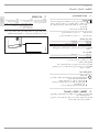
If you cannot remedy the fault, notify your qualified contractor.
To facilitate and speed up your enquiry, please provide the serial
number from the type plate (000000-0000-00000):
Nr.: 000000-0000-00000
D0000041614

6 | PHB 13-24 www.stiebel-eltron.com
INSTALLATION
Safety
INSTALLATION
7. Safety
Only a qualified contractor should carry out installation, commis-
sioning, maintenance and repair of the appliance.
7.1 General safety instructions
We guarantee trouble-free function and operational reliability only
if original accessories and spare parts intended for the appliance
are used.
!
Material losses
Observe the maximum inlet temperature. Higher tem-
peratures may damage the appliance. You can limit the
maximum inlet temperature by installing a central ther-
mostatic valve.
7.2 Instructions, standards and regulations
Note
Observe all applicable national and regional regulations
and instructions.
- The IP 25 (hoseproof) rating can only be ensured with a cor-
rectly fitted cable grommet.
- The specific electrical resistance of the water must not fall
below that stated on the type plate. In a linked water net-
work, observe the lowest electrical water resistance (see
chapter "Specification/ Application areas/ Conversion table").
Your water supply utility will advise you of the specific electri-
cal resistance or conductivity of the water.
8. Appliance description
8.1 Standard delivery
The following are delivered with the appliance:
- Wall mounting bracket
- Threaded stud for wall mounting bracket
- Installation template
- 2 twin connectors (cold water with shut-off valve)
- Flat gaskets
- Cable grommet (power cable from above/ below)
- Screws/ rawl plugs for securing the back panel to allow for
water connection on finished walls
For appliance replacement:
- 2 tap extensions
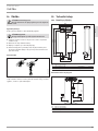
9. Preparations
9.1 Installation site
!
Material losses
Install the appliance in a room free from the risk of frost.
Always install the appliance vertically and near the draw-off
point.
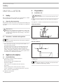
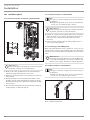
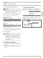
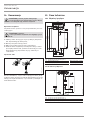
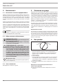
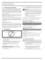
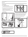
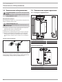
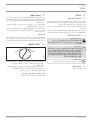
The appliance is suitable for undersink and oversink installation.
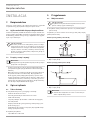
Undersink installation
26�02�02�1345
1
2
1 Cold water inlet
2 DHW outlet
Oversink installation
12
26�02�02�1344
1 Cold water inlet
2 DHW outlet
Note
Mount the appliance on the wall. The wall must have
a sufficient load-bearing capacity.

www.stiebel-eltron.com PHB 13-24| 7
ENGLISH
INSTALLATION
Installation
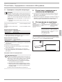
9.2 Water installation
- Never operate with preheated water.
- No safety valve is required.
- Safety valves are not permissible in the DHW pipe.
Flush the water line thoroughly.
Ensure that the flow rate for switching on the appliance is
achieved (see chapter "Specification/ Data table", On). In-
crease the mains water pressure if the required flow rate is
not achieved with the draw-off valve fully opened.
Taps/valves
Use appropriate pressure taps. Open vented taps are not permitted.
Thermostatic pressure valves must be suitable for hydraulically
controlled instantaneous water heaters.
Note
Never use the shut-off valve in the cold water inlet to
reduce the flow rate. It is intended for shutting off the
appliance.
Permissible water line materials
- Cold water supply line:
Galvanised steel pipe, stainless steel pipe, copper pipe or
plastic pipe
- DHW outlet line:
Pipes made from stainless steel, copper or plastic
!
Material losses
If plastic pipework systems are used, take into account the
maximum inlet temperature and the maximum pressure
(see chapter "Specification/ Data table").
Flexible water connection lines
If the appliance is installed with flexible water connection
lines, ensure that the pipe bends with bayonet fittings do not
become twisted inside the appliance.
Secure the back panel at the bottom with two additional
screws.
10. Installation
10.1 Standard installation
- Electrical connection from above; installation on unfinished
walls
- Water connection on unfinished walls
For further installation options, see chapter "Alternative installation
methods":
- Electrical connection from below on unfinished walls
- Electrical connection on finished walls
- Connecting a load shedding relay
- Water installation on finished walls
- Water connection on unfinished walls for appliance
replacement
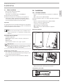
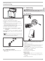
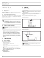
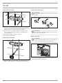
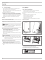
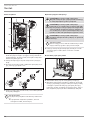
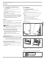
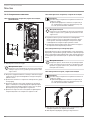
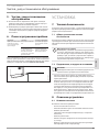
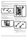
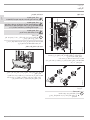
Opening the appliance
D0000041615
Open the appliance by releasing the snap lock.
NT
T-
so
X1
26�02�02�0762
Remove the back panel by pressing the two locking hooks and
pulling the base part of the back panel forwards.
Preparing the power cable
160
≥ 30
26�02�02�0887

8 | PHB 13-24 www.stiebel-eltron.com
INSTALLATION
Installation
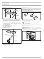
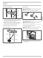
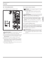
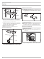
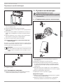
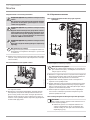
Fitting the wall mounting bracket
26�02�02�0972
Mark out the holes for drilling using the installation template.
If the appliance is to be installed with water connections on
finished walls, also mark out the fixing holes in the lower part
of the template.
Drill the holes and secure the wall mounting bracket with
2screws and 2rawl plugs (screws and rawl plugs are not part
of the standard delivery).
Fit the threaded stud provided.
Fit the wall mounting bracket.
Fitting the cable grommet
26�02�02�0950
Fit the cable grommet. For connecting cables >6mm², en-
large the hole in the cable grommet.
Making the water connection
!
Material losses
Carry out all water connection and installation work in
accordance with regulations.
26�02�02�0948
Seal and insert the twin connectors.
!
Material losses
Never use the shut-off valve in the cold water inlet to
reduce the flow rate.
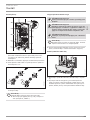
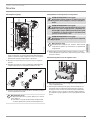
Preparing the back panel
!
Material losses
If you break open the wrong knock-out in the back panel
by mistake, you must use a new back panel.
D0000041896
Break out the cable grommet knock-out in the back panel.
Deburr any sharp edges with a file if necessary.

www.stiebel-eltron.com PHB 13-24| 9
ENGLISH
INSTALLATION
Installation
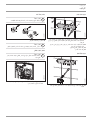
Installing the appliance
D0000041897
Push the back panel over the threaded stud and the cable
grommet. Pull the cable grommet by the locking hooks into
the back panel using pliers, until both locking hooks audibly
click into place.
Remove the protective transport plugs from the water
connections.
Press the back panel firmly into place and lock the fixing tog-
gle by turning it clockwise through 90°.
D0000041925
Screw the water connection pipes with flat gaskets onto the
twin connectors.
!
Material losses
The strainer must be fitted for the appliance to function.
When replacing an appliance, check whether the
strainer is installed (see chapter "Maintenance").
Making the electrical connection
WARNING Electrocution
Carry out all electrical connection and installation work
in accordance with relevant regulations.
WARNING Electrocution
The connection to the power supply must be in the form of
a permanent connection in conjunction with the remova-
ble cable grommet. Ensure the appliance can be separated
from the power supply by an isolator that disconnects all
poles with at least 3mm contact separation.
WARNING Electrocution
Ensure that the appliance is earthed.
!
Material losses
Observe the type plate. The specified voltage must match
the mains voltage.
Connect the power cable to the mains terminal (see chapter
"Specification/ Wiring diagram").
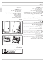
Fitting the base part of the back panel
3
L
3’
4
L
2’
1
L
1’
2
L
L
L
NT C
T- sol
l
X11
26�02�02�1348
Position the lower back panel on the main back panel and
click it into place.
Align the mounted appliance by loosening the fixing toggle,
aligning the power supply and back panel, and then re-tight-
ening the fixing toggle. If the back panel is not flush with the
wall, the appliance can be secured at the bottom with two
additional screws.

10 | PHB 13-24 www.stiebel-eltron.com
INSTALLATION
Installation
10.2 Installation options
10.2.1 Electrical connection from below on unfinished walls
D0000041898
Fit the cable grommet.
!
Material losses
If you break open the wrong knock-out in the back panel
by mistake, you must use a new back panel.
Break out the cable grommet knock-out in the back panel.
Deburr any sharp edges with a file if necessary.
Reposition the mains terminal in the appliance from the top
to the bottom.
Push the back panel over the threaded stud and the cable
grommet. Pull the cable grommet by the locking hooks into
the back panel using pliers, until both locking hooks audibly
click into place.
Press the back panel firmly into place and lock the fixing tog-
gle by turning it clockwise through 90°.
10.2.2 Electrical connection on finished walls
Note
This type of connection changes the protection rating of
the appliance.
Change the type plate. Cross out "IP 25" and mark the
box "IP 24". Use a ballpoint pen to do this.
!
Material losses
If you break open the wrong knock-out in the back panel
by mistake, you must use a new back panel.
Cleanly cut or break out the required cable entries in the back
panel (for positions, see chapter "Specification/ Dimensions
and connections"). Deburr any sharp edges with a file if
necessary.
Route the power cable through the cable grommet and con-
nect it to the mains terminal.
10.2.3 Connecting a load shedding relay
When operating additional electric appliances, such as electric
storage heaters, install a load shedding relay in the distribution
board. The relay responds when the instantaneous water heater
starts.
!
Material losses
Connect the phase that switches the load shedding relay
to the indicated terminal of the mains terminal in the
appliance (see chapter "Specification/ Wiring diagram").
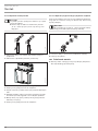
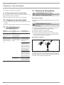
10.2.4 Water installation on finished walls
Note
This type of connection changes the protection rating of
the appliance.
Change the type plate. Cross out "IP 25" and mark the
box "IP 24". Use a ballpoint pen to do this.
26�02�02�0765
Fit water plugs with gaskets to seal the in-wall connection.
Fit a suitable pressure tap.

www.stiebel-eltron.com PHB 13-24| 11
ENGLISH
INSTALLATION
Commissioning
26�02�02�1006
Click the lower section of the back panel into place in the
upper section of the back panel.
Secure the connection pipes to the appliance.
Secure the back panel at the bottom with two additional
screws.
Cleanly break out the knock-outs in the appliance cover. De-
burr any sharp edges with a file if necessary.
Slide the lower back panel under the connection pipes of the
tap and click the lower back panel into place.
Secure the connection pipes to the appliance.
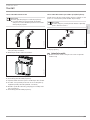
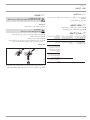
10.2.5 Water installation on unfinished walls for appliance
replacement
If the existing twin connectors of the old appliance only protrude
from the wall by approx.16mm, you cannot use the twin connec-
tors provided.
Note
With this connection, the cold water supply can only be
shut off within the domestic installation.
16
D0000041634
Seal and fit the screw-in tap extensions provided.
Connect the appliance.
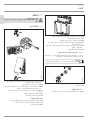
10.3 Completing the installation
Open the shut-off valve in the twin connector or the cold
water inlet line.
11. Commissioning
WARNING Electrocution
Commissioning must only be carried out by a qualified
contractor in accordance with safety regulations.
11.1 Initial start-up
D0000041620
Open and close all connected draw-off valves several times,
until all air has been purged from the pipework and the
appliance.
Carry out a tightness check.
Activate the safety pressure limiter by firmly pressing the reset
button (the appliance is delivered with the safety pressure
limiter deactivated).
Fit the appliance cover, ensuring it clicks into place. Check that
the appliance cover is seated correctly.
Switch the mains power ON.
Check the function of the appliance.
Appliance handover
Explain the appliance function to users and familiarise them
with its operation.
Make the user aware of potential dangers, especially the risk
of scalding.
Hand over these instructions.

12 | PHB 13-24 www.stiebel-eltron.com
INSTALLATION
Shutdown
11.2 Recommissioning
Vent the appliance and the cold water inlet line (see chapter "Set-
tings").
See chapter "Commissioning".
12. Shutdown
Isolate all poles of the appliance from the power supply.
Drain the appliance (see chapter "Maintenance").
13. Troubleshooting
Fault Cause Remedy
The flow rate is too low. The strainer in the appli-
ance is dirty.
Clean the strainer.
Flow meter will not start
despite tap being fully
opened.
The start-up volume
required to start up the
heating output has not
been reached.
Clean the strainer.
The appliance is not
generating hot water
despite audible start-up
of the differential pressure
switch.
Safety pressure limiter
(AP 3) has switched the
appliance off for safety
reasons.
Remove the cause of the
fault (e.g. faulty pressure
flush).
Protect the heating system
against overheating by
opening a draw-off valve
downstream of the appli-
ance for one minute. This
depressurises and cools
down the heating system.
Activate the safety
pressure limiter at flow
pressure by pressing the
reset button (see chapter
"Commissioning").
The heating system is
faulty.
Check the heating system
resistor and replace if
required.
14. Maintenance
WARNING Electrocution
Before any work on the appliance, ensure omnipolar dis-
connection from the power supply.
Draining the appliance
The appliance can be drained for maintenance work.
WARNING Burns
Hot water may escape when draining the appliance.
Close the shut-off valve in the twin connector or the cold
water inlet line.
Open all draw-off valves.
Undo the water connections on the appliance.
Store the dismantled appliance in a room free from the risk
of frost, as water residues remaining inside the appliance can
freeze and cause damage.
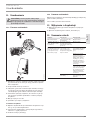
Cleaning the strainer
26�02�02�0949
If contaminated, clean the strainer in the threaded cold water fit-
ting. Close the shut-off valve in the cold water inlet line before
removing, cleaning and refitting the strainer.
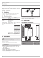
15. Specification
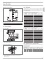
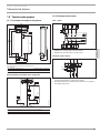
15.1 Dimensions and connections
395
100
485
325
45
5
93
226
190
50
112
190
35
c01
c06
b02
D0000017757
b02 Entry electrical cables I
c01 Cold water inlet Male thread G 1/2 A
c06 DHW outlet Male thread G 1/2 A

www.stiebel-eltron.com PHB 13-24| 13
ENGLISH
INSTALLATION
Specication
Alternative connection options
325
50
50
35
40
b03
b02
b04
b04
b04
D0000019778
b02 Entry electrical cables I
b03 Entry electrical cables II
b04 Entry electrical cables III
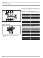
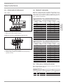
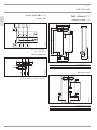
15.2 Wiring diagram
3/PE ~ 380 - 400 V
85�02�02�0002
1 Heater
2 High limit safety cut-out
3 Safety pressure limiter
Priority control with LR 1-A
85�02�02�0003�
2
1
1 Control cable to the contactor of the 2nd appliance (e.g. elec-
tric storage heater).
2 Control contact opens when switching the instantaneous
water heater on.
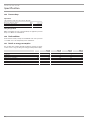
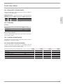
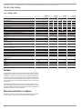
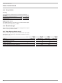
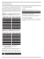
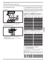
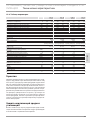
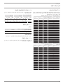
15.3 DHW output
The DHW output is subject to the mains voltage, the appliance's
connected load and the cold water inlet temperature. The rated
voltage and rated output can be found on the type plate (see chap-
ter "Troubleshooting").
Connected load in kW 38°C DHW output in l/min.
Rated voltage Cold water inlet temperature
380 V 400 V 5°C 10°C 15°C 20°C
9,6 4,2 4,9 6,0 7,6
12,9 5,6 6,6 8,0 10,2
15,2 6,6 7,8 9,4 12,1
17,1 7,4 8,7 10,6 13,6
10,6 4,6 5,4 6,6 8,4
14,3 6,2 7,3 8,9 11,3
16,8 7,3 8,6 10,4 13,3
19 8,2 9,7 11,8 15,1
12,2 5,3 6,2 7,6 9,7
16,3 7,1 8,3 10,1 12,9
19 8,2 9,7 11,8 15,1
21,7 9,4 11,1 13,5 17,2
13,5 5,8 6,9 8,4 10,7
18 7,8 9,2 11,2 14,3
21 9,1 10,7 13,0 16,7
24 10,4 12,2 14,9 19,0
Connected load in kW 50°C DHW output in l/min.
Rated voltage Cold water inlet temperature
380 V 400 V 5°C 10°C 15°C 20°C
9,6 3,0 3,4 3,9 4,6
12,9 4,1 4,6 5,3 6,1
15,2 4,8 5,4 6,2 7,2
17,1 5,4 6,1 7,0 8,1
10,6 3,4 3,8 4,3 5,0
14,3 4,5 5,1 5,8 6,8
16,8 5,3 6,0 6,9 8,0
19 6,0 6,8 7,8 9,0
12,2 3,9 4,4 5,0 5,8
16,3 5,2 5,8 6,7 7,8
19 6,0 6,8 7,8 9,0
21,7 6,9 7,8 8,9 10,3
13,5 4,3 4,8 5,5 6,4
18 5,7 6,4 7,3 8,6
21 6,7 7,5 8,6 10,0
24 7,6 8,6 9,8 11,4
15.4 Application areas/ conversion table
Specific electrical resistance and specific electrical conductivity (see
chapter "Data table").
Standard specifica-
tion at 15°C
20°C
25°C
Resist-
ance ρ ≥
Conductivity
σ ≤
Resist-
ance ρ ≥
Conductivity
σ ≤
Resist-
ance ρ ≥
Conductivity
σ ≤
Ωcm mS/m μS/cm Ωcm mS/m μS/cm Ωcm mS/m μS/cm
900 111 1111 800 125 1250 735 136 1361

14 | PHB 13-24 www.stiebel-eltron.com
INSTALLATION
Specication
15.5 Pressure drop
Taps/valves
Tap pressure drop at a flow rate of 10 l/min
Mono lever mixer tap, approx. MPa 0.04 - 0.08
Thermostatic valve, approx. MPa 0.03 - 0.05
Hand shower, approx. MPa 0.03 - 0.15
Sizing the pipework
When calculating the size of the pipework, an appliance pressure
drop of 0.1MPa is recommended.
15.6 Fault conditions
In the event of a fault, loads up to a maximum of 95 °C at a pressure
of 1.2MPa can occur temporarily in the installation.
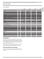
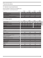
15.7 Details on energy consumption
The product data complies with EU regulations relating to the Di-
rective on the ecological design of energy related products (ErP).
PHB 13 PHB 18 PHB 21 PHB 24
233998 233999 234000 234001
Manufacturer STIEBEL ELTRON STIEBEL ELTRON STIEBEL ELTRON STIEBEL ELTRON
Load profile XS S S S
Energy efficiency class A A A A
Annual power consumption kWh 469 483 483 483
Energy conversion efficiency % 39 38 38 38
Sound power level dB(A) 15 15 15 15
Special information on measuring efficiency None None None None

www.stiebel-eltron.com PHB 13-24| 15
ENGLISH
INSTALLATION | GUARANTEE | ENVIRONMENT AND RECYCLING
Specication
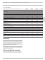
15.8 Data table
PHB 13 PHB 18 PHB 21 PHB 24
233998 233999 234000 234001
Electrical details
Rated voltage V 380 400 380 400 380 400 380 400
Rated output stage I min. kW 4,2 4,6 5,7 6,3 6,7 7,4 7,5 8,3
Rated output tage I max. kW 9,6 10,6 12,9 14,3 15,2 16,8 17,1 19
Rated output stage II min. kW 6,1 6,8 8,3 9,2 9,7 10,8 11 12,2
Rated output stage II max. kW 12,2 13,5 16,3 18 19 21 21,7 24
Rated current A 18,5 19,5 24,7 26 29,5 31 33,3 35
Fuse A 20 20 25 25 32 32 35 35
Phases 3/PE 3/PE 3/PE 3/PE
Frequency Hz 50/60 50/60 50/60 50/60
Specific resistance ρ
15
≥ (at ϑcold ≤25 °C) Ω cm 900 900 900 900
Specific conductivity σ
15
≤ (at ϑcold ≤25°C) μS/cm 1111 1111 1111 1111
Versions
Colour white white white white
IP-Rating IP25 IP25 IP25 IP25
Heating system heat generator Bare wire Bare wire Bare wire Bare wire
Connections
Water connection G 1/2 A G 1/2 A G 1/2 A G 1/2 A
Application limits
Max. permissible pressure MPa 1 1 1 1
Values
Max. permissible inlet temperature °C 25 25 25 25
Pressure drop at flow rate MPa 0,09 0,11 0,13 0,15
Flow rate for pressure drop l/min 3,9 4,5 5,6 6,3
Flow rate limit at l/min 4,7 5,9 7,0 7,8
DHW delivery l/min 7,0 9,4 11,1 12,5
Δϑ at DHW delivery K 26 26 26 26
Hydraulic data
Rated capacity l 0,4 0,4 0,4 0,4
Dimensions
Height mm 485 485 485 485
Width mm 226 226 226 226
Depth mm 93 93 93 93
Weights
Weight kg 3,6 3,6 3,6 3,6
Guarantee
The guarantee conditions of our German companies do not
apply to appliances acquired outside of Germany. In countries
where our subsidiaries sell our products a guarantee can only
be issued by those subsidiaries. Such guarantee is only grant
-
ed if the subsidiary has issued its own terms of guarantee. No
other guarantee will be granted.
We shall not provide any guarantee for appliances acquired in
countries where we have no subsidiary to sell our products.
This will not aect warranties issued by any importers.
Environment and recycling
We would ask you to help protect the environment.
After use,
dispose of the various materials in accordance with national
regulations.
GUARANTEE
ENVIRONMENT AND RECYCLING

16 | PHB 13-24 www.stiebel-eltron.com
OBSAH | ZVLÁŠTNÍ POKYNY
ZVLÁŠTNÍ POKYNY
OBSLUHA
1. Obecné pokyny ��������������������������������������������� 17
1.1 Bezpečnostní pokyny ������������������������������������������ 17
1.2 Jiné symboly použité vtéto dokumentaci ������������������ 17
1.3 Měrné jednotky ������������������������������������������������� 17
2. Bezpečnost �������������������������������������������������� 18
2.1 Použití vsouladu súčelem������������������������������������18
2.2 Všeobecné bezpečnostní pokyny ���������������������������� 18
2.3 Kontrolní symbol ������������������������������������������������ 18
3. Popis přístroje ���������������������������������������������� 18
4. Nastavení ��������������������������������������������������� 18
4.1 Doporučené nastavení pro armatury ����������������������� 19
5. Čištění, péče a údržba ������������������������������������� 19
6. Odstranění problémů �������������������������������������� 19
INSTALACE
7. Bezpečnost �������������������������������������������������� 20
7.1 Všeobecné bezpečnostní pokyny ����������������������������20
7.2 Předpisy, normy a ustanovení �������������������������������20
8. Popis přístroje ���������������������������������������������� 20
8.1 Rozsah dodávky ������������������������������������������������� 20
9. Příprava ����������������������������������������������������� 20
9.1 Místo montáže ��������������������������������������������������� 20
9.2 Vodovodní instalace �������������������������������������������� 21
10. Montហ������������������������������������������������������ 21
10.1 Standardní montáž ��������������������������������������������� 21
10.2 Alternativy montáže �������������������������������������������� 24
10.3 Dokončení montáže �������������������������������������������� 25
11. Uvedení do provozu ���������������������������������������� 26
11.1 První uvedení do provozu �������������������������������������26
11.2 Opětovné uvedení do provozu��������������������������������26
12. Uvedení mimo provoz ������������������������������������� 26
13. Odstraňování poruch �������������������������������������� 26
14. Údržba ������������������������������������������������������� 27
15. Technické údaje �������������������������������������������� 27
15.1 Rozměry a přípojky��������������������������������������������� 27
15.2 Schéma elektrického zapojení ������������������������������� 28
15.3 Výkon teplé vody ������������������������������������������������ 28
15.4 Oblast použití/ Převodní tabulka ���������������������������� 29
15.5 Ztráty tlaku ������������������������������������������������������� 29
15.6 Podmínky vpřípadě poruchy ��������������������������������� 29
15.7 Datos sobre el consumo energético ������������������������� 29
15.8 Tabulka údajů ��������������������������������������������������� 30
ZÁRUKA
ŽIVOTNÍ PROSTŘEDÍ A RECYKLACE
ZVLÁŠTNÍ POKYNY
- Přístroj smí používat děti od 3let a osoby se sní-
ženými fyzickými, senzorickými nebo mentálními
schopnostmi nebo snedostatečnými zkušenostmi
a znalostmi pouze pod dozorem, nebo poté, co
byly poučeny obezpečném používání přístroje a
jsou si vědomy nebezpečí, která zjeho používání
plynou. Nenechávejte děti, aby si spřístrojem
hrály. Čištění a údržbu, kterou má provádět uži-
vatel, nesmí provádět samotné děti bez dozoru.
- Armatura může za provozu dosáhnout teploty
vyšší než 60 °C. Pokud je výstupní teplota vyšší
než 43°C hrozí nebezpečí opaření.
- Přístroj musí být možné odpojit odsíťové přípojky
navšech pólech navzdálenost nejméně 3mm.
- Uvedené napětí se musí shodovat se síťovým
napětím.
- Přístroj musí být připojen k ochrannému vodiči.
- Přístroj musí být trvale připojen k pevné kabeláži.
- Upevněte přístroj způsobem popsaným vkapitole
„Instalace/ Montáž“.
- Dodržujte maximální dovolený tlak (viz kapitola
„Instalace/ Technické údaje/ Tabulka stechnic-
kými údaji“).
- Měrný odpor vody z vodovodní sítě nesmí být
podkročen (viz kapitola „Instalace/ Technické
údaje/ Tabulka stechnickými údaji“).
- Vypusťte přístroj způsobem podle popisu vkapi-
tole „Instalace/ Údržba/ Vypuštění přístroje“.
- Přístroj není schválen kdohřevu předehřáté vody.

OBSLUHA
Obecné pokyny
www.stiebel-eltron.com PHB 13-24| 17
ČESKY
OBSLUHA
1. Obecné pokyny
Kapitoly „Zvláštní pokyny“ a „Obsluha“ jsou určeny uživatelům
přístroje a instalačním technikům.
Kapitola „Instalace“ je určena instalačním technikům.
Upozornění
Dříve, než zahájíte provoz, si pozorně přečtěte tento
návod a pečlivě jej uschovejte.
Případně předejte návod dalšímu uživateli.
1.1 Bezpečnostní pokyny
1.1.1 Struktura bezpečnostních pokynů
!
UVOZUJÍCÍ SLOVO - Druh nebezpečí
Zde jsou uvedeny možné následky nedodržení bezpeč-
nostních pokynů.
Zde jsou uvedena opatření kodvrácení nebezpečí.
1.1.2 Symboly, druh nebezpečí
Symbol Druh nebezpečí
Úraz
Úraz elektrickým proudem
Popálení
(popálení, opaření)
1.1.3 Uvozující slova
UVOZUJÍCÍ SLOVO Význam
NEBEZPEČÍ Pokyny, jejichž nedodržení má za následek vážné nebo
smrtelné úrazy.
VÝSTRAHA Pokyny, jejichž nedodržení může mít za následek vážné
nebo smrtelné úrazy.
POZOR Pokyny, jejichž nedodržení může mít za následek střed-
ně vážné nebo lehké úrazy.
1.2 Jiné symboly použité vtéto dokumentaci
Upozornění
Obecné pokyny jsou označeny symbolem zobrazeným
vedle.
Texty upozornění čtěte pečlivě.
Symbol Význam
Věcné škody
(poškození přístroje, následné škody, poškození životního
prostředí)
Likvidace přístroje
Tento symbol vás vyzývá kurčitému jednání. Potřebné úkony
jsou popsány po jednotlivých krocích.
1.3 Měrné jednotky
Upozornění
Pokud není uvedeno jinak, jsou všechny rozměry uvedeny
vmilimetrech.
!
!

OBSLUHA
Bezpečnost
18 | PHB 13-24 www.stiebel-eltron.com
2. Bezpečnost
2.1 Použití vsouladu súčelem
Přístroj je určen kpoužití vdomácnostech. Mohou jej tedy bezpeč-
ně obsluhovat neškolené osoby. Lze jej používat i mimo domác-
nosti, např. v drobném průmyslu, pokud způsob použití v takových
oblastech odpovídá určení přístroje.
Tlakové zařízení je určeno kohřevu pitné vody. Přístroj může zá-
sobovat jedno nebo několik odběrných míst.
Jiné použití nebo použití nad rámec daného rozsahu je považová-
no za použití vrozporu surčením. Kpoužití vsouladu surčením
patří také dodržování tohoto návodu a návodů kpoužívanému
příslušenství.
Upozornění
Přístroj není schválen kdohřevu předehřáté vody.
2.2 Všeobecné bezpečnostní pokyny
POZOR popálení
Armatura může za provozu dosáhnout teploty vyšší než
60 °C.
Pokud je výstupní teplota vyšší než 43°C hrozí nebezpečí
opaření.
!
VÝSTRAHA úraz
Přístroj smějí používat děti od 3let a osoby se sníženými
fyzickými, senzorickými nebo mentálními schopnostmi
nebo snedostatkem zkušeností a znalostí pouze pod do-
zorem, nebo po poučení obezpečném použití přístroje, a
poté, co porozuměly nebezpečí, která zjeho použití ply-
nou. Nenechávejte děti, aby si spřístrojem hrály. Čištění
a údržbu, kterou má provádět uživatel, nesmí provádět
samotné děti bez dozoru.
!
Věcné škody
Uživatel musí přístroj a armaturu chránit před mrazem.
2.3 Kontrolní symbol
Viz typový štítek na přístroji.
3. Popis přístroje
Hydraulicky řízený průtokový ohřívač zahřívá vodu, která protéká
přístrojem. Po otevření armatury a překročení množství k zapnutí
(viz kapitola „Technické údaje/ Tabulka údajů“), se automaticky
zapne topný výkon. Množství vody a teplotu můžete nastavit na
armatuře.
Můžete volit mezi 2 výkonovými stupni. Navíc se v závislosti na
průtokovém množství hydraulicky řídí 2 výkonové stupně.
Regulace průtoku přístroje kompenzuje kolísání tlaku a zajišťuje
tak maximálním způsobem stejnoměrné teploty. Regulace vyme-
zuje průtokové množství a zaručuje tak vždy dostatečné navýšení
teploty pitné vody.
Topný systém
Topný systém sholou spirálou je vybaven plastovým tlakovým
pláštěm. Topný systém je vhodný pro vodu snízkým i vyšším ob-
sahem vápenných solí, systém je do značné míry necitlivý vůči
zanášení vodním kamenem. Topný systém zajišťuje rychlou a
účinnou přípravu teplé vody.
4. Nastavení
D0000041612
2 1
1 Částečný výkon
Při nízkém průtokovém množství se spíná 1/3 topného vý-
konu, při vyšším průtokovém množství 2/3 topného výkonu.
Toto nastavení je např. vhodné k mytí rukou.
2 Plný výkon
V případě nižšího průtokového množství se spíná poloviční
topný výkon, při vyšším průtokovém množství plný topný
výkon. Toto nastavení je např. vhodné k oplachování.
Nastavte přepínač výkonu do požadované polohy.
Doporučené nastavení při použití armatury s termostatem
Nastavte přepínač výkonu na plný výkon.

OBSLUHA
Čištění, péče a údržba
www.stiebel-eltron.com PHB 13-24| 19
ČESKY
4.1 Doporučené nastavení pro armatury
Upozornění
Pokud nelze při plně otevřeném odběrném ventilu a
plném výkonu dosáhnout dostatečné teploty na výtoku,
protéká přístrojem více vody, než může topný systém
ohřát (přístroj na hranici výkonu).
Zmenšete množství vody naodběrném ventilu.
nižší odebírané množství = vysoká teplota na výtoku
velké odebírané množství = nízká teplota na výtoku
Armatura se dvěma pákami
Výkonový stupeň Oblast použití
Částečný výkon Umyvadlo
Plný výkon Koupelnová vana, sprcha, dřez
V případě příliš vysoké teploty a plně otevřené armatury při-
míchejte studenou vodu.
Páková baterie
Výkonový stupeň Oblast použití
Plný výkon vše
Otočte páku armatury na nejvyšší teplotu.
Zcela otevřete armaturu.
Zvyšte teplotu na výtoku tak, že pomalu uzavřete armaturu.
Snižte teplotu na výtoku tak, že přimísíte studenou vodu
nebo, pokud možno, více otevřete armaturu.
Po přerušení přívodu vody
!
Věcné škody
Po přerušení dodávky vody je nutné přístroj opětovně
uvést do provozu pomocí následujících kroků, aby nedo-
šlo k poškození topného systému sholou spirálou.
Odpojte přístroj od napětí vypnutím pojistek.
Otevřete armaturu na dobu jedné minuty, dokud
nejsou přístroj a předřazená přípojka studené vody
odvzdušněné.
Opět zapněte napájení ze sítě.
5. Čištění, péče a údržba
Nepoužívejte abrazivní čisticí prostředky nebo prostředky
obsahující rozpouštědla. Košetřování a údržbě přístroje stačí
vlhká textilie.
Kontrolujte pravidelně armatury. Vodní kámen na výtocích
zarmatur odstraníte běžnými prostředky kodstranění vodní-
ho kamene.
6. Odstranění problémů
Problém Příčina Odstranění
I když je ventil teplé vody
zcela otevřen, přístroj se
nezapne.
Došlo kvýpadku elektric-
kého napájení.
Zkontrolujte pojistky
vnitřní instalace.
Průtokové množství je
příliš malé nato, aby
se zapnul topný výkon.
Perlátor v armatuře nebo
sprchová hlavice jsou za-
neseny vodním kamenem
nebo jsou znečištěné.
Vyčistěte perlátor nebo
sprchovou hlavici a zbav-
te je vodního kamene.
Pokud nelze příčinu odstranit, kontaktujte odborníka. Pro lepší a
rychlejší pomoc mu sdělte číslo (č. 000000-0000-00000), které je
uvedeno natypovém štítku:
Nr.: 000000-0000-00000
D0000041614

20 | PHB 13-24 www.stiebel-eltron.com
INSTALACE
Bezpečnost
INSTALACE
7. Bezpečnost
Instalaci, uvedení do provozu, údržbu a opravy přístroje smí pro-
vádět pouze odborník.
7.1 Všeobecné bezpečnostní pokyny
Řádnou funkci a spolehlivý provoz lze zaručit pouze vpřípadě
použití původního příslušenství a originálních náhradních dílů
určených pro tento přístroj.
!
Věcné škody
Dodržujte maximální vstupní teplotu. Při vyšších tep-
lotách může dojít k poškození přístroje. Instalací cent-
rální termostatické armatury můžete omezit maximální
teplotu přítoku.
7.2 Předpisy, normy a ustanovení
Upozornění
Dodržujte všechny národní a místní předpisy a ustano-
vení.
- Krytí IP 25 (ochrana proti stříkající vodě) je zaručeno pouze v
případě odborně instalované kabelové průchodky.
- Měrný elektrický odpor vody nesmí být menší než hodnota
uvedená na typovém štítku. Vpřípadě propojení několika
vodovodních sítí je nezbytné vzít vúvahu nejnižší elektrický
odpor vody (viz kapitola „Technické údaje/ Oblasti použití/
Převodní tabulka“). Hodnoty měrného elektrického odporu
vody nebo elektrické vodivosti vody zjistíte u vašeho dodava-
tele vody.
8. Popis přístroje
8.1 Rozsah dodávky
Spolu spřístrojem dodáváme:
- Nástěnná závěsná lišta
- Svorník sezávitem pro zavěšení nazeď
- Montážní šablona
- 2 dvojité vsuvky (studená voda suzavíracím ventilem)
- Plochá těsnění
- Kabelová průchodka (elektrické přívodní vedení nahoře/
dole)
- Šrouby/ hmoždinky kpřipevnění zadní stěny vpřípadě mon-
táže navodovodní přípojku nastěnu
Pro výměnu přístroje:
- 2 prodloužení kohoutu
9. Příprava
9.1 Místo montáže
!
Věcné škody
Přístroj smí být instalován pouze vmístnosti chráněné
před mrazem.
Přístroj montujte ve svislé poloze vblízkosti odběrného
místa.
Přístroj je vhodný k montáži pod a nad umyvadlo.
Montáž pod umyvadlo
26�02�02�1345
1
2
1 Přívod studené vody
2 Výtok teplé vody
Montáž nad umyvadlo
12
26�02�02�1344
1 Přívod studené vody
2 Výtok teplé vody
Upozornění
Namontujte přístroj nastěnu. Stěna musí mít dosta-
tečnou nosnost.
Strona się ładuje...
Strona się ładuje...
Strona się ładuje...
Strona się ładuje...
Strona się ładuje...
Strona się ładuje...
Strona się ładuje...
Strona się ładuje...
Strona się ładuje...
Strona się ładuje...
Strona się ładuje...
Strona się ładuje...
Strona się ładuje...
Strona się ładuje...
Strona się ładuje...
Strona się ładuje...
Strona się ładuje...
Strona się ładuje...
Strona się ładuje...
Strona się ładuje...
Strona się ładuje...
Strona się ładuje...
Strona się ładuje...
Strona się ładuje...
Strona się ładuje...
Strona się ładuje...
Strona się ładuje...
Strona się ładuje...
Strona się ładuje...
Strona się ładuje...
Strona się ładuje...
Strona się ładuje...
Strona się ładuje...
Strona się ładuje...
Strona się ładuje...
Strona się ładuje...
Strona się ładuje...
Strona się ładuje...
Strona się ładuje...
Strona się ładuje...
Strona się ładuje...
Strona się ładuje...
Strona się ładuje...
Strona się ładuje...
Strona się ładuje...
Strona się ładuje...
Strona się ładuje...
Strona się ładuje...
Strona się ładuje...
Strona się ładuje...
Strona się ładuje...
Strona się ładuje...
Strona się ładuje...
Strona się ładuje...
Strona się ładuje...
Strona się ładuje...
Strona się ładuje...
Strona się ładuje...
Strona się ładuje...
Strona się ładuje...
Strona się ładuje...
Strona się ładuje...
Strona się ładuje...
Strona się ładuje...
Strona się ładuje...
Strona się ładuje...
Strona się ładuje...
Strona się ładuje...
Strona się ładuje...
Strona się ładuje...
Strona się ładuje...
Strona się ładuje...
-
 1
1
-
 2
2
-
 3
3
-
 4
4
-
 5
5
-
 6
6
-
 7
7
-
 8
8
-
 9
9
-
 10
10
-
 11
11
-
 12
12
-
 13
13
-
 14
14
-
 15
15
-
 16
16
-
 17
17
-
 18
18
-
 19
19
-
 20
20
-
 21
21
-
 22
22
-
 23
23
-
 24
24
-
 25
25
-
 26
26
-
 27
27
-
 28
28
-
 29
29
-
 30
30
-
 31
31
-
 32
32
-
 33
33
-
 34
34
-
 35
35
-
 36
36
-
 37
37
-
 38
38
-
 39
39
-
 40
40
-
 41
41
-
 42
42
-
 43
43
-
 44
44
-
 45
45
-
 46
46
-
 47
47
-
 48
48
-
 49
49
-
 50
50
-
 51
51
-
 52
52
-
 53
53
-
 54
54
-
 55
55
-
 56
56
-
 57
57
-
 58
58
-
 59
59
-
 60
60
-
 61
61
-
 62
62
-
 63
63
-
 64
64
-
 65
65
-
 66
66
-
 67
67
-
 68
68
-
 69
69
-
 70
70
-
 71
71
-
 72
72
-
 73
73
-
 74
74
-
 75
75
-
 76
76
-
 77
77
-
 78
78
-
 79
79
-
 80
80
-
 81
81
-
 82
82
-
 83
83
-
 84
84
-
 85
85
-
 86
86
-
 87
87
-
 88
88
-
 89
89
-
 90
90
-
 91
91
-
 92
92


STIEBEL ELTRON PHB 13-24 Operation Instruction
- Typ
- Operation Instruction
Powiązane artykuły
-
STIEBEL ELTRON PEG 13-24 Operation Instruction
-
-
-
-
-
-
STIEBEL ELTRON PEY Operation Instruction
-
-
Inne dokumenty
-
 Eldom Invest 60-100 DU Instrukcja instalacji
-
Gorenje GT 10 U Instrukcja obsługi
-
DeLOCK 60263 Karta katalogowa
-
-
DeLOCK 60254 Karta katalogowa
-
-
-
-
-
